Abstract
The vibration acceleration of collecting plates, which is the core indicator of rapping performance in an electrostatic precipitator’s vibration rapping process, is determined by magnetic force of a quadratic electromagnetic exciter. The larger exciter provides the larger magnetic force, but the installation space for the exciter is limited. Accordingly, this paper presents the optimal design of quadratic electromagnetic exciter to maximize the magnetic force with constraint that the size of exciter is constant. A design optimization problem was formulated in order to find the quadratic electromagnetic exciter shape parameters that maximized the magnetic force. The magnetic force of the quadratic electromagnetic exciter was evaluated using the commercial electromagnetic analysis software “MAXWELL”. For efficient design, we employed metamodel-based design optimization using design of experiments (DOE), metamodels, and an optimization algorithm equipped in PIAnO (Process Integration, Automation and Optimization), a commercial PIDO (Process Integration and Design Optimization) tool. Using the proposed design approach, the optimal magnetic force was increased by 1.68 % compared to the initial one. This result demonstrates the effectiveness of the established analysis and design procedure for the quadratic electromagnetic exciter.
1. Introduction
The quadratic electromagnetic exciter for vibrating rapper of an ESP (Electrostatic Precipitator) has been developed to remove the collected dust from the collecting plates without any direct impact on the collecting plates [1]. Fig. 1 shows a schematic diagram of the quadratic electromagnetic exciter. It consists of an inner steel yoke with 4 rectangle-shape small permanent magnets, an outer steel yoke with 4 large permanent magnets, a coil, coil housing, case, stinger and plate spring. The inner and outer magnets create an enormous magnetic flux density in the air gap, which results in a strong magnetic force because the permanent magnets are placed in a double layer. Fig. 2 shows the schematic diagram and the operation of the electromagnetic exciter. The excitation is created by the magnetic force called “Lorentz force” which is created by the flux generated from the permanent magnets and the sinusoidal electric current applied to the electromagnetic coil. The Lorentz force is expressed by Eq. (1):
where n is the number of electric coil winding turns, Bg is the magnetic flux density in the air gap, i is the input electric current, leffective is the effective length of coil in the air gap.
Accordingly, the dust-rapping of ESP system is determined by magnetic force of the exciter. For larger magnetic force, it needs more turns of electric coil, the higher residual flux density of the permanent magnets in the air gap, and higher electric current or more effective length of coil in the air gap. The more turns of electric coil or the longer effective length of electric coil makes the size of exciter larger. Also, more turns of electric coil creates more heat which has bad influence on the dynamic performance of the exciter and higher electric current needs more electric energy consumption. However, the larger magnetic flux density in the air gap can be accomplished by the optimization design without the drawbacks mentioned above.
Fig. 1Structure of the prototype exciter
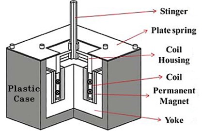
Fig. 2Operation of the electromagnetic exciter
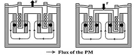
Fig. 3Design optimization process of the quadratic electromagnetic exciter using PIAnO [7]
![Design optimization process of the quadratic electromagnetic exciter using PIAnO [7]](https://static-01.extrica.com/articles/14845/14845-img3.jpg)
A design optimization problem was formulated in order to find the quadratic electromagnetic exciter shape parameters that maximized the magnetic force by maximizing the magnetic flux density in the air gap. The magnetic force was evaluated by electromagnetic analysis of the quadratic electromagnetic exciter using MAXWELL, commercial electromagnetic finite element analysis software (Version 14.0, ANSOFT, USA). For efficient design, we employed metamodel-based design optimization using design of experiments (DOE), metamodels, and an optimization algorithm equipped in PIAnO (Version 3.6, PIDOTECH, KOREA), a commercial PIDO (Process Integration and Design Optimization) tool. In this study, an orthogonal array (OA) was employed for DOE, Kriging models for metamodeling, and an evolutionary algorithm (EA), respectively [2, 3]. The magnetic force of the quadratic electromagnetic exciter was evaluated using MAXWELL according to the change in design variables specified by a DOE. Metamodeling building a metamodel that approximates the relationship between performance index and design variables of a real model by using the analysis results at sampling points specified by a DOE. Since the design optimization problem approximated by Kriging models may have many local optima, an evolutionary algorithm was used to obtain global optimum solution. Fig. 3 shows the design optimization process of the quadratic electromagnetic exciter using PIAnO [4-6].
2. Design problem formulation
2.1. Design objective function
Purpose of the quadratic electromagnetic exciter is providing sufficient vibration force to moving parts assembly in limited space. To achieve this goal, maximization of the magnetic force FMagnetic (Lorentz force) was set as objective function in this research. So that, whole design process tried for finding optimum values of design variables which can derive higher magnetic force in Z-direction.
2.2. Design variables
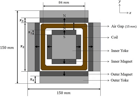
Fig. 4 and 5 show respectively the schematic diagram and the top view of magnetic part of the exciter excluding the plastic case, plate spring, and stinger. The whole size of magnetic part of the exciter is predetermined as150 mm×150 mm×70 mm. There are 4 inner magnets and 4 outer magnets respectively. The electromagnetic coil is located at the center of air gap between inner magnets and outer magnets those are respectively attached to inner steel yokes and outer steel yokes. The design factors which have influence on the magnetic force of the exciter are the electric coil winding turns, the effective coil length, the input electric current and the magnetic flux density in the air gap. The specification of electric coil such as coil length coil winding turns, input electric current are predetermined as shown in Table 1. The magnetic flux density in the air gap is decided by the size of air gap, the sizes of inner magnets and inner yokes and sizes of outer permanent magnets and outer steel yokes. The size of air gap is 15 mm. And, the sizes of inner steel yokes are automatically determined by the sizes of inner permanent magnets because the predetermined size of electric coil makes the size of inner yokes be dependent on size of inner permanent magnets. However the thickness of outer yoke can be manipulated regardless of size outer magnet. In results, the thickness of inner magnet (x1), the width of outer magnet (x2), the thickness of outer magnet (x3) and the thickness of outer yoke (x4) are chosen as the design variables. The height of permanent magnet is determined as the maximum value considering the whole size of magnetic part of exciter. Table 2 shows the initial values, lower values, and upper values of the design variables.
Table 1Specification of electric coil and input current
Number of turns | 215 turns |
Coil length | 84 mm×4sides |
Input current | 1 ampere |
Table 2Upper and lower bounds of the design variables
Design variable | Lower bound | Initial | Upper bound | |
x1 | Inner mag. T | 9 | 10 | 13 |
x2 | Outer mag. W | 98 | 100 | 106 |
x3 | Outer mag. T | 6 | 10 | 10 |
x4 | Outer yoke T | 16 | 16 | 20 |
Fig. 4Design variables and fixed constants of the exciter
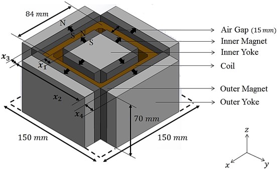
Fig. 5Flux leakage areas in the exciter
2.3. Design problem formulation
The design formulation for the optimal design of the exciter is prescribed as follows:
3. Design optimization
3.1. Design of experiments
The number of design variables is four and each design variables have 5 Levels. So, we employed the orthogonal array (OA) L25(56), which is one of the DOEs for computer experiments. To perform the electromagnetic analysis of the quadratic electromagnetic exciter, we built 25 finite element exciter models according to the change in design variables. Table 5 shows 25 OA sample points.
3.2. Electromagnetic FEM (static analysis)
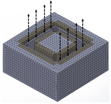
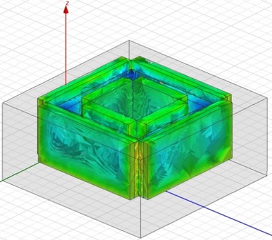
Magnetic force in air-gap makes coil and coil housing components which are connected with collecting plate through a shaft move in vertical direction. So this force should be predicted before design the exciter. 25 EA prototypes of the exciter model were created with the orthogonal array above, and electromagnetic static analysis was conducted with these models to derive estimated value of magnetic force in Z-direction for each model. The MAXWELL, commercial electromagnetic analysis program was used to achieve this objective. Fig. 6(a) and (b) show a pre-meshed 3-dimensional finite element model of the exciter with an arrowed component that is a moving part (coil) in this device and distribution of magnetic flux density in the exciter.
Table 525 OA sample points
Case | x1 | x2 | x3 | x4 |
1 | 9 | 98 | 6 | 20 |
2 | 9 | 98 | 7 | 19 |
3 | 9 | 98 | 8 | 18 |
4 | 9 | 98 | 9 | 17 |
5 | 9 | 98 | 10 | 16 |
6 | 10 | 100 | 6 | 20 |
7 | 10 | 100 | 7 | 19 |
8 | 10 | 100 | 8 | 18 |
9 | 10 | 100 | 9 | 17 |
10 | 10 | 100 | 10 | 16 |
11 | 11 | 102 | 6 | 20 |
12 | 11 | 102 | 7 | 19 |
13 | 11 | 102 | 8 | 18 |
14 | 11 | 102 | 9 | 17 |
15 | 11 | 102 | 10 | 16 |
16 | 12 | 104 | 6 | 20 |
17 | 12 | 104 | 7 | 19 |
18 | 12 | 104 | 8 | 18 |
19 | 12 | 104 | 9 | 17 |
20 | 12 | 104 | 10 | 16 |
21 | 13 | 106 | 6 | 20 |
22 | 13 | 106 | 7 | 19 |
23 | 13 | 106 | 8 | 18 |
24 | 13 | 106 | 9 | 17 |
25 | 13 | 106 | 10 | 16 |
Fig. 6(a) Pre-meshed 3-dimensional FE exciter model; (b) Distribution of magnetic flux density in the FE exciter model
a)
b)
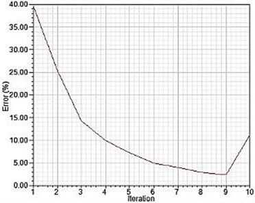
MAXWELL was using DRS8 solve as an analysis problem solver, and on average, about 12.700 EA of mesh elements were created on the exciter. During the analysis process, 10 times of computation process were performed for each model on the orthogonal array. Final analysis error was about 11.37 % in the end and a Fig. 7 shows error convergence trend to that value.
Fig. 7Error convergence of FE exciter models
DOE results are shown in Table 6. The magnetic force of the quadratic electromagnetic exciter was evaluated using MAXWELL according to the change in design variables specified by the OA table. In DOE results, the magnetic force value of case No. 25 is increased by 1.68 % compared to the initial design. Although the result of case No. 25 was enhanced, we performed the metamodel-based design optimization to determine the global optimum solution that maximized the magnetic force.
Table 6Static magnetic force simulation results by DOE
Case | x1 | x2 | x3 | x4 | Magnetic force (N) |
1 | 9 | 98 | 6 | 20 | 26.16 |
2 | 9 | 98 | 7 | 19 | 27.26 |
3 | 9 | 98 | 8 | 18 | 28.22 |
4 | 9 | 98 | 9 | 17 | 29.12 |
5 | 9 | 98 | 10 | 16 | 29.84 |
6 | 10 | 100 | 6 | 20 | 26.39 |
7 | 10 | 100 | 7 | 19 | 27.39 |
8 | 10 | 100 | 8 | 18 | 28.28 |
9 | 10 | 100 | 9 | 17 | 29.07 |
10 | 10 | 100 | 10 | 16 | 29.78 |
11 | 11 | 102 | 6 | 20 | 26.58 |
12 | 11 | 102 | 7 | 19 | 27.54 |
13 | 11 | 102 | 8 | 18 | 28.42 |
14 | 11 | 102 | 9 | 17 | 29.18 |
15 | 11 | 102 | 10 | 16 | 29.81 |
16 | 12 | 104 | 6 | 20 | 26.81 |
17 | 12 | 104 | 7 | 19 | 27.78 |
18 | 12 | 104 | 8 | 18 | 28.61 |
19 | 12 | 104 | 9 | 17 | 29.33 |
20 | 12 | 104 | 10 | 16 | 29.97 |
21 | 13 | 106 | 6 | 20 | 27.22 |
22 | 13 | 106 | 7 | 19 | 28.11 |
23 | 13 | 106 | 8 | 18 | 28.88 |
24 | 13 | 106 | 9 | 17 | 29.51 |
25 | 13 | 106 | 10 | 16 | 30.17 |
3.3. Metamodeling
Metamodeling builds a metamodel that approximates the relationship between performance index (magnetic force) and design variables by using the analysis results at the sampling points specified by a DOE. To generate an appropriate metamodel, we used the Approximate Model Wizard equipped in PIAnO. The Approximate Model Wizard compared the accuracies of several popular metamodels (Polynomial Regression, RBF, Kriging, etc.) using “predicted R2” and generated the best one automatically. In metamodeling result, the “predicted R2” value of Kriging model for the magnetic force is 98.29 %.
3.4. Optimization algorithm
Since the Kriging model generated in Section 3.3 may have many local optima, an evolutionary algorithm (EA) equipped in PIAnO was used to obtain the global optimum solution. The EA, one of the global optimization methods, evolves a population (i.e., a set of design variables) generation by generation by repetitively using evolutionary operators such as selection, recombination and mutation [8-10].
3.5. Design optimization results
Using the proposed design approach, the optimal magnetic force was increased by 1.68 % compared to the initial design. Since the metamodel-based design optimization result yields predicted optimum values (Approximate Optimization pred) of performance index (magnetic force) evaluated by metamodel, the actual value (Approximate Optimization act) must be evaluated by running MAXWELL at the optimal design point. In Fig. 8, both AO_pred and AO_act are drawn along with the initial values. They are very close to each other, which confirm the accuracy of the Kriging model we employed. In Fig. 8, the objective function values are shown, which present the predicted and actual magnetic forces. The predicted and actual values were increased to 30.2 and 30.19, respectively, from 29.8.
Fig. 8Comparison of AO_pred and AO_act values
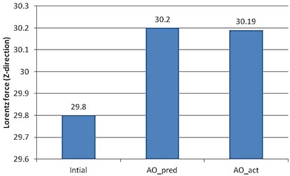
Table 7Optimum design variable values along with the initial, lower, and upper bound values
Design variable | Lower bound | Initial | Optimum | Upper bound | Unit | |
x1 | Inner mag. T | 9 | 10 | 12.98 | 13 | mm |
x2 | Outer mag. W | 98 | 100 | 105.97 | 106 | mm |
x3 | Outer mag. T | 6 | 10 | 9.97 | 10 | mm |
x4 | Outer yoke T | 16 | 16 | 16.02 | 20 | mm |
The optimum design variable values are listed along with the initial, lower and upper bound values in Table 7. The optimum values of Inner mag. T (x1) and Outer mag. W (x2) were found close to upper bound while the optimum and initial values of Outer mag. T (x3) and Outer yoke T (x4) were almost the same.
4. Conclusion
The quadratic electromagnetic exciter was optimally designed for enhancing magnetic force (Lorentz force) by using an appropriate design optimization method and a PIDO tool. A design optimization problem was formulated in order to determine the shape parameters of inner, outer magnets and outer yoke. The magnetic force of the quadratic electromagnetic exciter was evaluated using commercial electromagnetic analysis program “MAXWELL”. For efficient design, we employed metamodel-based design optimization using design of experiments, metamodels and an optimization algorithm in PIAnO. Using the proposed design approach, the optimal magnetic force of the quadratic electromagnetic exciter was found to be increased by 1.68 % compared to the initial design.
References
-
Choi J. H., Kim J. H., Lim B. D., Kim J. H. Mathematical vibration modeling for an electrostatic precipitator system. Journal of Vibroengineering, Vol. 15, Issue 1, 2013.
-
Choi J. S. General use PIDO solution, PIAnO. The Korean Society of Mechanical Engineers, Vol. 52, Issue 2, 2012, p. 12-13.
-
Hedayat A. S., Sloane N. J. A., Stufken J. Orthogonal arrays: theory and applications. Springer Verlag, New York, 1999.
-
Dette H., Lopez I. M. Maximin efficient design of experiment for exponential regression models. Journal of Statistical Planning and Inference, Vol. 136, Issue 12, 2006, p. 4397-4418.
-
Park C. H., Lee Y. M., Choi D. H. Design optimization of an automotive vent valve using kriging models. The Korean Society of Automotive Engineers, Vol. 19, Issue 6, 2011, p. 1-9.
-
Shin Y. S., Lee Y. B., Ryu J. S., Choi D. H. Sequential approximate optimization using kriging metamodels. The Korean Society of Mechanical Engineers, Vol. 29, Issue 9, 2005, p. 1199-1208.
-
Park C. H. PIAnO (Process integration, automation and optimization) user’s manual 3.6. Pidotech Inc., 2013.
-
Buckley J. J., Feuring T. Evolutionary algorithm solution to fuzzy problems: Fuzzy linear programming. Fuzzy Set and Systems, Vol. 109, Issue 1, 2000, p. 35-53.
-
Ray T., Kang T., Chye S. K. An evolutionary algorithm for constrained optimization. Proceedings of the Genetic and Evolutionary Computation Conference, San Francisco, California, 2000, p. 771-777.
-
Jeong M. J., Dennis B. H., Yoshimura S. Multidimensional clustering interpretation and its application to optimization of coolant passage of a turbine blade. Journal of Mechanical Design, Transactions of the ASME, Vol. 127, 2005, p. 215-221.
-
Papalambros P. Y., Wilde D. J. Principles of optimal design: modeling and computation. Cambridge University Press, Cambridge, 2000.
-
Jeon Y. H., Jeon S. Y., Noh J. H., Kim J. H., Kim J. H., Lee D. H. A study on approximation techniques for the multidisciplinary optimization. The Korean Society for Aeronautical & Space Sciences, Spring Symposium Collection of Dissertations, 2005, p. 23-29.
About this article
This research was supported by a grant from the Urban Railroad Technology Development Program (09 Urban Railroad A-01), funded by Ministry of Land, Infrastructure and Transport of the Korean Government. In addition, the authors express gratitude to PIDOTECH Inc. that provides PIAnO software as a PIDO tool for this study.
