Abstract
To construct a precise model for investigating the dynamic characteristics and vibration control strategies of flexible manipulators, restraints of the joint should be fully considered and precisely described. Considering the effect of the elastic restraints of the joint, this paper investigated the mode and vibration characteristics of a flexible manipulator with elastic restraint joint (FMERJ). The elastic restraint model and boundary conditions of the FMERJ were established. With the boundary conditions, natural frequency equation and mode shapes of the FMERJ were derived. Subsequently, vibration responses of the FMERJ were obtained. Numerical results demonstrated that the mode and vibration characteristics of the FMERJ are obviously different from that of flexible manipulator with fixed restraint joint (FMFRJ) which was commonly idealized in present research, and the elastic restraints of the joint have a considerable effect on the dynamic characteristics and should be considered in precise dynamic analysis and further constructing vibration control strategies of the flexible manipulator.
1. Introduction
Flexible manipulators are extensively used in industrial applications, particularly in aerospaces and robotics, for the motivations such as better energy efficiency, higher operation speed and improved mobility [1-2]. The lightweight and highly flexible nature, however, lead to a challenging problem that an unwanted residual vibration emerged when the manipulator reaches the predetermined position, which conspicuously affects the position accuracy and operation precision and reduces the service life of the manipulator [3-5]. Hence, many literatures have studied the vibration characteristics and control strategies to reduce the vibration of flexible manipulators [1, 4, 6-10].
The first step to effectively investigate vibration characteristics or design efficient control strategies is constructing a precise dynamic model. Generally, as shown in Fig. 1, a flexible manipulator can be modeled as a flexible beam connected by a moving rigid base [1, 3]. In this case, the flexible manipulator undergoes a rigid motion and flexible motion which interact through the joint. Research has indicated that restraints of mechanical joints have a considerable effect on the dynamic characteristics of structures [11-12]. In static analysis, the joint is commonly idealized as absolutely rigid and this assumption can obtain an acceptable result. Nevertheless, the fully rigid restraint is absent and extremely difficult to achieve. For example, for the flexible manipulator connected to the rigid base by welding or bolting which is commonly used in the experiment to investigate dynamic characteristics or design control strategies, the joint is not absolutely rigid and presents a certain elastic restraint. In dynamic analysis, the elastic restraints of the joint have a considerable effect on the results due to the coupling effect between the flexible manipulator and rigid base. Furthermore, Gaul [13] investigated that the joint will be affected by an external dynamic load during the rigid base moving, and the flexible manipulator will present more complicated dynamic behaviors. Hence, considering the restraints of the joint as absolutely rigid will introduce a certain precision error in dynamic analysis, moreover the error is significant for the operation precision of flexible manipulators.
Fig. 1Dynamic model of a flexible manipulator

A review of recent literatures, however, shows that most of the existing works considering the elastic restraint are mainly related to the natural characteristics of large-scale structures, such as high-rise buildings, bridges and shells [14-17], and the dynamic characteristic and vibration control of FMERJs have not obtained sufficient attentions. Considering the elastic restraints of the joint will enhance the interaction of rigid motion and flexible motion and increase nonlinear factors in dynamic analysis, and the dynamic model establishment and vibration control will consequently become complex [18]. In the present literatures, the joint is considered as fixed restraint when design or verify a control strategy. As specifically indicated in [3], to construct a more accurate dynamic model for investigating the dynamic characteristics of flexible manipulators, the elastic restraints of the joint should be fully considered and precisely described.
In this paper, the elastic restraints of the joint are considered, and the mode and vibration characteristics of the FMERJ are investigated which are essential to further construct an effective vibration control strategy. In Section 2, the restraints of the joint are equivalent to torsional restraint and linear restraint, and the elastic restraint model and boundary conditions of the FMERJ are established. In Section 3, with the boundary conditions, natural frequency equation and mode shapes of the FMERJ are derived. Subsequently, the vibration responses of the FMERJ are obtained in Section 4. Results are presented and discussed in Section 5 which shows the characteristics of natural frequencies, mode shapes and vibration responses of the FMERJ. Finally, the paper is concluded with a brief summary in Section 6.
2. Elastic restraint model and boundary conditions of the FMERJ
In this section, elastic restraint model and boundary conditions of the FMERJ are presented. Considering the effect of elastic restraints, the restraints of the joint are equivalent to torsional restraint and linear restraint in the direction of the base moving as shown in Fig. 2. Here, kt and k denote the coefficients of torsional restraint and linear restraint, respectively, and y(x,t) represents the transverse vibration displacement of x. For the construction of a dynamic model, assumptions are made as follows: (a) The beam satisfies the Bernoulli-Euler Beam assumptions and the axial deformation can be ignored. Consequently, transverse bending vibration of the beam is the primary motion. (b) The effect of gravity can be neglected which is always existed in real applications.
Fig. 2Elastic restraint model of the FMERJ

Fig. 3Force and moment analysis of the fixed end of the FMERJ
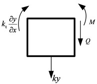
When excited, the flexible manipulator presents a bending deformation and the elastic restraint joint devotes a force and moment which can be expressed as ky and kt∂y∂x, respectively. The force and moment can be balanced by the shear force and moment of the flexible manipulator denoted as Q and M, respectively, as shown in Fig. 3.
Thus, the following equations can be obtained:
According to the differencial equation for small deflection and differencial equation of equilibrium, the shear force Q and moment M can be stated as follows:
where E is Young’s modulus of the beam; I is the cross-sectional moment of inertia about the neural axis of the beam, I=bh3/12,  where b is the width and h is the thickness of the beam, respectively.
Therefore, combining Eqs. (1)-(4), boundary condition of the fixed end of the FMERJ can be specified as:
For shear force and moment of the free end are zero, boundary condition of the free end of the FMERJ can be expressed as:
3. Natural frequencies and mode shapes of the FMERJ
Natural frequency equation and mode shapes of the FMERJ are derived in this section. According to the assumptions presented in Section 2, a Bernoulli-Euler Beam is utilized. Moreover, based on the Bernoulli-Euler Beam theory, the influence of the shear deformation and cross-sectional moment of inertia about the neutral axis can be ignored in low-frequency vibration. Therefore, the differential equation of transverse free vibration can be expressed as [19]:
where ρ and A denote the mass density and cross-sectional area of the beam, respectively.
Assuming that constant c meets the relationship, c2=EI/ρA, Eq. (7) can be simplified as:
Eq. (8) is a fourth-order partial differential equation and the general solution can be expressed as the sum of the normal modes. Using the method of variables separation, the transverse vibration displacement can be written as:
where φ(x) and T(t) are functions of x and t, respectively.
Substituting Eq. (9) into Eq. (8), the vibration differential equation becomes:
In Eq. (10), the left part is merely related to x, while the middle part is merely related to t. To satisfy the equivalence, they should be an equivalent real constant, here assumed as ω2. Therefore, Eq. (10) can be further simplified as:
The general solution of Eq. (11a) is:
where β4=ω2/c2=ρAω2/EI; C1, C2, C3 and C4 are constants determined by the boundary conditions.
By comparing with the undamped single degree of freedom (SDOF) system, it can be obtained that Eq. (11b) is similar with the expression of the undamped SDOF system, thus the general solution of Eq. (11b) can be described as:
where B1 and B2 are constants determined by initial conditions. Moreover, it indicates that ω assumed in Eq. (10) denotes the natural frequency of the flexible beam, and must be a positive real constant, or the solution of Eq. (11b) will divergent and cannot represent the vibration.
For simplifying the analysis, φ(x), φ'(x), φ''(x), and φ'''(x) are expressed as:
Substituting Eq. (9) into Eq. (5) and Eq. (6), the boundary conditions described by Eq. (5) and Eq. (6) are specified as:
and
respectively.
Combining Eq. (14) and Eq. (15), the following equation can be obtained:
where λ=β2EI.
Similarly, combining Eq. (14) and Eq. (16), the following equation are received:
Then, combining Eq. (17) and Eq. (18), the result can be presented as:
where:
For mode shapes expressed by Eq. (12) must exist a non-zero solution, the coefficient, C1, C2, C3 and C4 cannot be all zero. Therefore, to assure the non-zero solution of Eq. (19), value of the determinant of the coefficients should be zero and meets the following condition:
By expanding the determinant, the natural frequency equation of the FMERJ can be obtained as:
According to the relationships, β4=ρAω2/EI and λ=β2E, by solving Eq. (21), the natural frequencies of the FMERJ can be expressed as:
where j=1, 2, …, and α=√EIρAL4.
Subsequently, combining Eq. (12), Eq. (17) and Eq. (19), the mode shapes of the FMERJ are obtained as:
where:
Generally, the coefficient C1 can be assigned C1=1, and Eq. (23) can be subsequently simplified as:
+ζj(sinβjx+2ktβjλjkkt-λ2jcoshβjx-kkt+λ2jkkt-λ2jsinhβjx).
4. Vibration responses of the FMERJ
In this section, vibration responses of the FMERJ are obtained. Substituting the natural frequencies ωj and mode shapes φj obtained by Eq. (22) and Eq. (25), respectively, into Eq. (9) and Eq. (13), the primary transverse vibration of the FMERJ can be obtained as:
According to the assumed modes method [3], vibration responses of the FMERJ can be expressed as:
where B1j and B2j are determined by initial conditions.
Assuming that initial displacem ent and initial velocity of the FMERJ are y(x,0) and ˙y(x,0), respectively, results can be obtained as:
Multiplying Eq. (28) with ρAφi and integrating along the length direction, based on the orthogonality of mode shapes depicted as follows:
B1j and B2j can be determined as:
where Mpj=∫L0ρAφ2jdx, which is called the mode mass.
Substituting Eq. (30) into Eq. (27), the vibration responses of the FMERJ are subsequently obtained as:
5. Results
Results are divided into three parts. Firstly, natural frequencies of the FMERJ are presented. Secondly, characteristics of mode shapes of the FMERJ are analyzed. Thirdly, characteristics of vibration responses of the FMERJ are shown. Properties of the flexible beam which is considered as a manipulator in the numerical simulations, are length L=650 mm, width b=50 mm, thickness t=2 mm, Young’s modulus E=197 GPa, volumetric density ρ=7850 kg/m3 and Poisson’s ratio μ=0.26. The elastic restraints of the joint are investigated for the case that the flexible manipulator is connected to a rigid base by bolting. In the computations, only the first three modes are considered.
5.1. Natural frequencies of the FMERJ
The first three natural frequencies of the FMERJ are presented in Table 1, and compared with that of flexible manipulator with fixed restraint joint (FMFRJ) which neglects the elastic restraint and is commonly idealized in present research.
Table 1First three nature frequencies of the flexible manipulator with different restraints joint: elastic restraint and fixed restraint (24.07, 150.84, 422.36)
k= 1.0×10⁵ | k= 1.0×10⁶ | k= 1.0×10⁷ | |||||||
1st | 2nd | 3rd | 1st | 2nd | 3rd | 1st | 2nd | 3rd | |
kt= 1.0×10⁵ | 37.47 | 267.72 | 438.82 | 37.77 | 267.75 | 638.01 | 37.80 | 267.77 | 651.23 |
kt= 1.0×10⁶ | 24.70 | 144.04 | 339.10 | 24.31 | 151.35 | 418.28 | 24.85 | 155.93 | 436.84 |
kt= 1.0×10⁷ | 24.00 | 140.27 | 335.82 | 24.08 | 149.92 | 414.33 | 24.14 | 151.21 | 422.87 |
kt= 1.0×10⁸ | 23.93 | 139.90 | 335.52 | 24.06 | 149.77 | 413.96 | 24.07 | 150.75 | 421.58 |
It is obvious from the results that natural frequencies of the FMERJ are obviously different from that of FMFRJ, and the elastic restraints of the joint have a considerable effect on the natural frequencies. Moreover, the effects of linear restraint and torsional restraint on the natural frequencies are different. Specifically, the first three natural frequencies increase with the linear restraint while decrease with the torsional restraint, and the trend is more obvious for higher order frequencies. When the restraint stiffness of the joint is great enough, the frequencies present a minor change and gradually toward the situation of FMFRJ. Therefore, for the restraint stiffness of the bolted connection is usually less than 1.0×10⁷ and cannot reach that of fixed restraint, the elastic restraints of the joint should be considered.
5.2. Mode shapes of the FMERJ
The characteristics of the first three mode shapes of the FMERJ are presented in Fig. 4. It can be obtained that the elastic restraints of the joint have a considerable effect on the mode shapes. The mode shapes of the FMERJ are conspicuously different from that of FMFRJ. As shown in Fig. 4(a), the first mode shape gradually towards stable with an increasing restraint stiffness of the joint, and cannot reach that of FMFRJ however. Figs. 4(b) and 4(c) indicate that the second and third mode shapes can consistent with that of FMFRJ when the restraint stiffness of the joint is great enough. Therefore, for the situation of bolting, considering the mode shapes of the FMERJ as that of FMFRJ will generate a certain error in precise analysis, especially for the lower order mode shapes.
Furthermore, the results of Fig. 4 show that the frequency of the third mode shape of the FMERJ is obviously higher that of FMFRJ, and increases with an increasing linear restraint. Moreover, it can be obtained from Fig. 4 that the mode shapes of the FMERJ are similar to that of flexible manipulator with hinged restraint joint (FMHRJ). As the torsional restraint increased, the restraint state of the joint varies from hinged restraint to fixed restraint and the frequencies become smaller, particularly for the higher order mode shapes. It can be further drawn that the torsional restraint has a more significant effect on the restraint state.
5.3. Vibration responses of the FMERJ
To investigate the effect of the elastic restraints of the joint on the steady-state responses of the flexible manipulator, the end point (x=0.65) is considered. In the computation, the initial displacement and initial velocity are assigned y(0.65,0)=0.001 and ˙y(0.65,0)=0, respectively.
The vibration responses of the FMERJ are presented in Fig. 5. It is obvious that the elastic restraints of the joint have a considerable effect on the vibration responses of the flexible manipulator. Fig. 5 clearly shows that the response amplitudes of the FMERJ are smaller than that of FMFRJ and the difference will significantly impact the precise dynamic analysis of the FMERJ. This further indicates that the elastic restraints of the joint have a noticeable effect on vibration reduction, and the mechanism can be used for structure design of flexible manipulators. Furthermore, it can be obtained from Fig. 6 that the response frequencies of the FMERJ are obviously higher than that of FMFRJ. This indicates that, due to the elastic restraints of the joint, the vibration responses of the FMERJ are more intense. Moreover, Fig. 5(a) shows that linear restraint has a smaller effect on the response frequencies, while the effect of torsional restraint on the response frequencies are considerable as presented in Figs. 5(b) and 5(c). Conclusions can be drawn that the effect of the elastic restraints of the joint on the vibration responses of the flexible manipulator is noticeable. For the positioning of the end-effector for precision jobs should involve very small amplitudes of vibration, ideally no vibration at all [3], considering the restraints of the joint as the ideal situation of fixed restraint will introduce a certain error in precise dynamic analysis and vibration control of flexible manipulator.
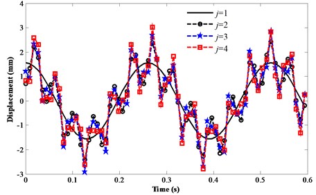
To compute the vibration responses of the flexible manipulator, the number of terms in the infinite series or the value of j in Eq. (31) should be assigned. Fig. 6 presents the vibration responses of the FMFRJ with different assumed terms. It can be obtained that when the value of j is greater than 3, the results present a minor change and rapidly toward stable. As indicated in [3], only the first several modes are usually retained and the higher modes are neglected in the assumed mode method. Thus, the infinite series in Eq. (31) only keeps the first three terms in the computation.
Fig. 4First three mode shapes of the FMERJ
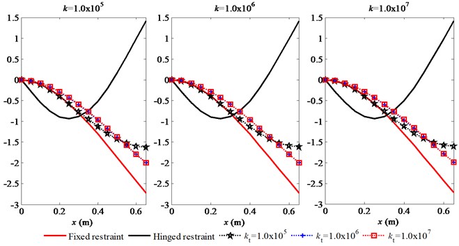
a) The first mode shape of the FMERJ
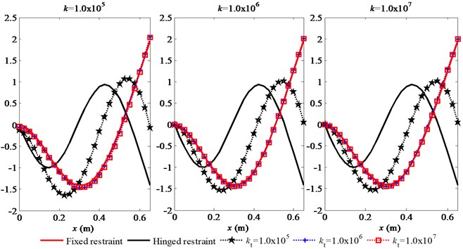
b) The second mode shape of the FMERJ
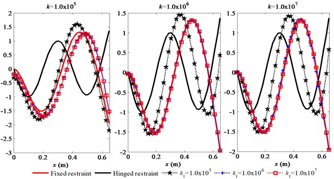
c) The third mode shape of the FMERJ
Fig. 5Vibration responses of the FMERJ
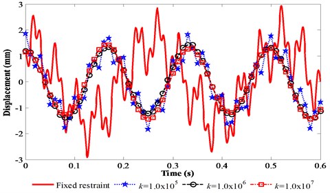
a) Effect of liner restraint on the vibration responses of the FMERJ
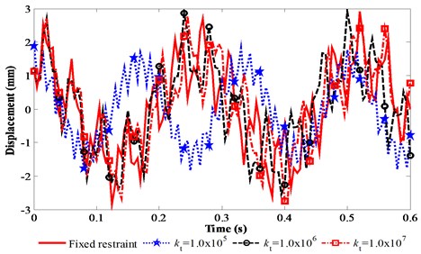
(b) Effect of torsional restraint on the vibration responses of the FMERJ
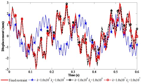
(c) Effect of liner restraint and torsional restraint on the vibration responses of the FMERJ
Fig. 6Vibration responses of the FMFRJ with different assumed terms
6. Conclusions
In this paper, considering the elastic restraints of the joint, mode and vibration characteristics of a flexible manipulator with elastic restraint joint (FMERJ) are investigated which is significant to construct a dynamic model and vibration control strategy. It was obtained that the elastic restraints of the joint had a noticeable effect on the dynamic characteristics of flexible manipulators, and natural frequencies, mode shapes and vibration responses of the FMERJ were obviously different from that of flexible manipulator with fixed restraint joint (FMFRJ). Specifically, the natural frequencies of the FMERJ were obviously impact by the elastic restraints of the joint, for increasing with the linear restraint and decreasing with the torsional restraint which was more noticeable for higher order frequencies. Furthermore, the mode shapes of the FMERJ were conspicuously different from that of FMFRJ, and torsional restraint had a more significant effect on the restraint state. Moreover, the elastic restraints of the joint had a considerable effect on the vibration responses of the flexible manipulator, the response amplitudes of the FMERJ were smaller than that of FMFRJ while the response frequencies of the FMERJ were higher than that of FMFRJ. This further indicated that elastic restraints of the joint had a noticeable effect on vibration reduction and the mechanism can be used for structure design of flexible manipulators. It demonstrated that the effect of the elastic restraints of the joint on dynamic characteristics were noticeable and should be considered in precise dynamic analysis and vibration control of flexible manipulators.
References
-
Mohsen D., Nader J., Zeyu L., Darren M.D. An observer-based piezoelectric control of flexible Cartesian robot arms: theory and experiment. Control Engineering Practice, Vol. 12, 2004, p. 1041-1053.
-
Ge S. S., Lee T. H., Zhu G. Asymptotically stable end-point regulation of a flexible SCARA/Cartesian robot. IEEE/ASME Transaction on Mechatronics, Vol. 3, Issue 2, 1998, p. 138-144.
-
Dwivedy S. K., Eberhard P. Dynamic analysis of flexible manipulators, a literature review. Mechanism and Machine Theory, Vol. 41, 2006, p. 749-777.
-
Zhicheng Q. Adaptive nonlinear vibration control of a Cartesian flexible manipulator driven by a ball screw mechanism. Mechanical Systems and Signal Processing, Vol. 30, 2012, p. 248-266.
-
Maria A. N., Jorge A. C., Ambrósio L. M., Roseiro A. A., Vasques C. M. A. Active vibration control of spatial flexible multibody systems. Multibody System Dynamics, Vol. 30, Issue 1, 2013, p. 13-35.
-
Ge S. S., Lee T. H., Gong J. Q. A robust distributed controller of a single-link SCARA/Cartesian smart materials robot. Mechatronics, Vol. 9, 1999, p. 65-93.
-
Dadfarnia M., Jalili N., Xian B., Dawson D. M. A Lyapunov-based piezoelectric controller for flexible Cartesian robot manipulators. Journal of Dynamic Systems Measurement and Control Transactions of the ASME, Vol. 126, 2004, p. 347-358.
-
Changjoo S., Chinsuk H., Weui B. J. Active vibration control of beam structures using acceleration feedback control with piezoceramic actuators. Journal of Sound and Vibration, Vol. 331, 2012, p. 1257-1269.
-
Kerem G., Bradley J. B., Edward J. P. Vibration control of a single-link flexible manipulator using an array of fiber optic curvature sensors and PZT actuators. Mechatronics, Vol. 19, 2009, p. 167-177.
-
Zhicheng Q., Mingli S., Bin W., Zhuowei X. Genetic algorithm based active vibration control for a moving flexible smart beam driven by a pneumatic rod cylinder. Journal of Sound and Vibration, Vol. 331, 2012, p. 2233-2256.
-
Ibrahim R. A., Pettit C. L. Uncertainties and dynamic problems of bolted joints and other fasteners. Journal of Sound and Vibration, Vol. 279, Issue 35, 2005, p. 857-936.
-
Song Y., Hartwigsen C. J., McFarland D. M., Vakakis A. F., Bergman L. A. Simulation of dynamics of beam structures with bolted joints using adjusted Iwan beam elements. Journal of Sound and Vibration, Vol. 273, 2004, p. 249-276.
-
Gaul L., Nitsche R. The role of friction in mechanical joints. Applied Mechanics Reviews, Vol. 54, 2001, p. 93-106.
-
Javier A., Luis Eduardo P. R. Use of global ductility for design of structure-foundation systems. Soil Dynamics and Earthquake Engineering, Vol. 31, 2011, p. 1018-1026.
-
Yuehua C., Guoyong J., Zhigang L. Free vibration analysis of circular cylindrical shell with non-uniform elastic boundary constraints. International Journal of Mechanical Sciences, Vol. 74, 2013, p. 120-132.
-
Haijun Z., Wanyou L., Binglin L., Li W. L. Free vibrations of cylindrical shells with elastic-support boundary conditions. Applied Acoustics, Vol. 73, 2012, p. 751-756.
-
HuuTai T., Minwo P., DongHo C. A simple refined theory for bending, buckling, and vibration of thick plates resting on elastic foundation. International Journal of Mechanical Sciences, Vol. 73, 2013, p. 40-52.
-
Subudhi B., Morris A. S. Dynamic modelling, simulation and control of a manipulator with flexible links and joints. Robotics and Autonomous Systems, Vol. 41, Issue 4, 2002, p. 257-270.
-
Singiresu S. R. Mechanical vibration. Fourth Edition, Pearson Education Inc., 2004.
About this article
This research work was partially supported by the National High Technology Research and Development Program of China (2013AA06A411), the National Natural Science Foundation of China (No. 51305444), the Project Funded by the Priority Academic Program Development of Jiangsu Higher Education Institutions, and the Doctoral Fund of Ministry of Education under Grants (No. 20120095120013). The authors sincerely thank the reviewers for their constructive comments and suggestions which made substantial improvements to this paper.
