Abstract
Accurate calculation on circumferential natural frequencies of stator structure in permanent magnet synchronous motor (PMSM) is very important for predicting the vibration and noise of PMSM. The analytical modal formula for the stator structure in PMSM is proposed, starting from the mathematical displacement model of cylindrical shell, then deriving the analytical formula for the stator structure. Firstly, finite element method (FEM) is applied to analyze the circumferential natural frequencies of cylindrical shells with different length, wall thickness, mean diameter, diameter-thickness ratio, size and installation position of terminal box. The influences on circumferential natural frequencies of cylindrical shells are studied. Furthermore, a new analytical formula considering diameter-thickness ratio for calculating circumferential natural frequencies of cylindrical shells is developed. Compared with the results of FEM, the correctness of the analytical formula is verified. Then, novel analytical formulas considering stiffness errors are proposed to calculate the circumferential natural frequencies of stator core and motor case. Compared with the results of FEM, the effectiveness of analytical method is validated. Finally, a new analytical formula considering diameter-thickness ratio, stiffness errors, existence of terminal box and mutual constraints is presented to calculate the circumferential natural frequencies of stator structure. Compared with the results of FEM and experimental method, the relative errors are respective within |4.43 %| and |3.38 %|. The validity of analytical formula is confirmed.
1. Introduction
As compared to other motors, due to their high power density, good dynamic performance and high energy conversion efficiency, permanent magnet synchronous motors (PMSMs) have been more and more widely used in many fields, such as home appliances, machine tools, automobile, military and other fields [1, 2], but there are still many problems to be solved. One of the problems is the electromagnetic vibration and noise generated during the operation of the motor. In 1987, Zhu Ziqiang, professor of the University of Sheffield, proved that the radial electromagnetic force acting on the stator surface and various order modes of stator structure were two key reasons for producing electromagnetic vibration and noise of PMSM [3]. Therefore, in order to effectively suppress electromagnetic vibration and noise, the modal frequencies of the motor should be away from the frequencies of electromagnetic force waves corresponding to order.
Accurate prediction on the modal frequencies of motor is the premise of suppressing electromagnetic vibration and noise [4, 5]. However, completely theoretical analysis on motor's mode is very complex. In 2006, Gieras J. F. et al. [6] presented that the stator teeth, windings and insulation materials were simplified into cylindrical shell loaded on the stator yoke. The cylindrical shell, stator yoke and motor case form a system to calculate natural frequencies of stator structure and the results are much better than the traditionally calculating method. Therefore, the accurate calculation on the circumferential natural frequencies of cylindrical shells is of great importance. The cylindrical shell of stator in motor is also a basic component of engineering structure. It is of great theoretical significance and engineering value to study the vibration characteristics of cylindrical shell of stator.
Many scholars and experts have studied the vibration of cylindrical shell of stator in motor [4, 7-9]. A new wave method for predicting the natural frequencies of finite length cylindrical shells is introduced by Wang C. et al. in 2000, as shown in the literature [10]. Based on Flügge classical thin shell theory and orthotropic theory, Gan Lin et al adopted the wave propagation method to study the free vibration of cylindrical shell [11] in 2009. The formula of Donnel-Mushtari theory is considered to be the most simple and practical, and the Flügge and Sander formula is considered to be more accurate [12, 13]. However, all the formulas are derived from the case of thin shells, and the influence of the variation of the wall thickness and other parameters of cylindrical shells on the natural frequencies is not considered. Moreover, the calculating results will be greatly different in the case of the same cylindrical shell by using different formulas. The influence of wall thickness and other parameters on the circumferential natural frequencies of cylindrical shells and the calculating results of different formulas are analyzed in this paper.
This paper investigates the calculating method for the circumferential natural frequency of stator in PMSM. The analytical modal formula for the stator structure in PMSM is proposed, starting from the mathematical displacement model of cylindrical shell, then deriving the analytical formula for the stator structure. Firstly, the circumferential natural frequencies of cylindrical shells with different length, wall thickness, mean diameter, diameter-thickness ratio, size and installment position of terminal box are calculated by finite element method. The influences on the circumferential natural frequencies of cylindrical shells are studied. Compared with the results of Hoppe theory and Donnel-Mushtari theory, the improved analytical formula for calculating circumferential natural frequencies of cylindrical shells is obtained. Compared with the results of FEM, the validity of the formula is verified. Secondly, the circumferential natural frequencies of stator core and motor case which are simplified into cylindrical shells are calculated. The stiffness correction coefficient of model simplification is gained. Finally, the circumferential natural frequencies of stator structure are calculated by analytical method, FEM and experimental method. Compared with the results of FEM and experiment method, the correctness of the analytical method is confirmed.
The remaining of this paper is organized as follows. Section 2 briefly explains the methods for modal analysis: cylindrical shell theory, FEM and experimental method. Section 3 analyzes the influence of factors (length, wall thickness and so on) on the circumferential natural frequency of cylindrical shells. Section 4 presents analytical formulas for calculating circumferential natural frequency of stator core and motor case. Section 5 gives a comprehensively analytical formula for calculating circumferential natural frequency of stator structure, and this formula takes into account the factors that are proposed in Section 3 and Section 4. This section also gives the results of FEM and experimental method to verify the correctness of analytical method. The conclusions are depicted in the last section.
2. Methods for modal analysis
The methods for modal analysis mainly include theoretical method (analytical and energy methods) and experimental method. In this paper, the adopted analytical method is cylindrical shell theory and the adopted energy method is FEM.
2.1. Cylindrical shell theory
For the thin-walled cylinder, the natural frequency of the mth circumferential free vibrational mode can be expressed as:
On the basis of different theories, Km has different calculating methods, that is:
(1) Hoppe theory.
The formula for calculating circumferential (m ≥ 2) natural frequencies of cylindrical shells was first published by Hoppe in 1871 [14]. The lumped stiffness and mass:
where:
and substituting Eq. (2) and Eq. (3) into Eq. (1), the fm is obtained as:
(2) Donnel-Mushtari theory.
In addition to the Hoppe theory, the Donnel-Mushtari theory is also used to calculate circumferential natural frequencies of cylindrical shells. The calculating formula for lumped mass is the same as the Eq. (3), but the lumped stiffness [15]:
and substituting Eq. (3) and Eq. (6) into Eq. (1), thefm is obtained as:
2.2. Finite element method (FEM)
The more accurately analytical method for calculating circumferential natural frequencies is the “energy method” which is based on the Lagrange equation-finite element method.
A unit body is taken and the Lagrange function is established as follows [16]:
The equation of motion for the unit can be derived by using the Hamilton principle, the stress-strain relation and strain-displacement relation, that is:
Each unit of the system is set up and the equation of motion for vibrational system can be obtained, that is:
The natural frequency is generally undamped free vibration, so it makes F={0} and C={0}. According to the theory of differential equations, the solution of Eq. (10) can be expressed as:
and substituting Eq. (11) into Eq. (10), it can be obtained as follows:
Based on the theory of linear equation, the necessary and sufficient condition for non-zero solution is as follows:
The frequency and corresponding to non-zero solution vector of satisfying Eq. (12) and Eq. (13) are solved.
2.3. Natural frequency test
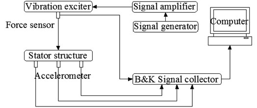
The modal testing software of vibration and noise test system 7753 of Danish B&K Company is used to test motor’s modes through the vibration exciter method in this paper. The modal testing system consists of prototype, signal collector, vibration exciter, signal generator, signal amplifier, accelerometer, force sensor and computer. The B&K modal testing system is depicted in Fig. 1.
Fig. 1B&K modal testing system
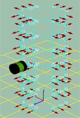
In this paper, the free mode of stator structure is studied, so the tested stator structure is hanged in the midair by elastic rope, as shown in Fig. 2. The experiment adopts the method with one point excitation and multipoint recording response to test the circumferential modes of stator structure. Firstly, the simplified model of the tested stator structure is modeled in the B&K Labshop software. Then, the circumference of the measured stator structure is the average set of 81 testing points, as described in Fig. 3. The occurring signal is set as a random signal. Average 100-time vibration is as one step, and each step uses three acceleration transducers to record the signals of 3 testing points. Finally, the frequency response function of each testing point and the established experimental simplified model are imported into the post processing software Reflex of the B&K [17]. Pulse Reflex Modal Analysis software analyzes the measured natural frequency data. Each frequency response function is attached to the corresponding to testing point of the model. When the modes are chosen, Polyference Time is used to extract the modes of each interval.
Fig. 2Modal testing spot of stator structure
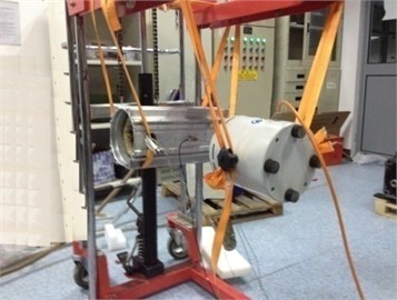
Fig. 3Diagrammatic sketch of exciting point and testing points in modal test
3. Analysis on factors affecting the circumferential natural frequencies of cylindrical shells
The FEM is used to respectively calculate circumferential natural frequencies of cylindrical shells with different length, wall thickness, mean diameter, diameter-thickness ratio, size and installation position of terminal box. The influences on the circumferential natural frequencies of cylindrical shells are researched. Compared with the calculating results of Hoppe theory and Donnel-Mushtari theory, the improved formula for calculating the circumferential natural frequencies of cylindrical shells is obtained.
3.1. Influence of length on the circumferential natural frequencies of cylindrical shells
The parameters of physical model used in modal calculation are shown in Table 1. According to the selected material trademark, the material properties are found by the handbook of common materials for motor [18]. By changing the length l of the cylindrical shells, the influence of it on the circumferential natural frequencies of cylindrical shells is studied.
Table 1Parameters for physical model of cylindrical shell
D | h | ρ | E | v |
0.1 | 0.004 | 7700 | 2.058e11 | 0.3 |
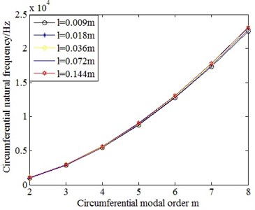
Fig. 4 is the comparison on the circumferential natural frequencies of cylindrical shells with different length. From this figure, it can be seen that the length of cylindrical shells has small influence on their circumferential natural frequencies, that is, the circumferential natural frequencies of cylindrical shells do not vary with their length.
Fig. 4Comparison on the circumferential natural frequencies of cylindrical shells with different length
3.2. Influence of wall thickness on the circumferential natural frequencies of cylindrical shells
By keeping 0.144 m length and 0.1 m mean diameter of cylindrical shells unchanged, the wall thickness h of cylindrical shells is changed to investigate its influence on circumferential natural frequencies of cylindrical shells. The material properties are shown in Table 1. The calculating results of FEM are depicted in Fig. 5.
Fig. 5Comparison on the circumferential natural frequencies of cylindrinal shells with different wall thickness
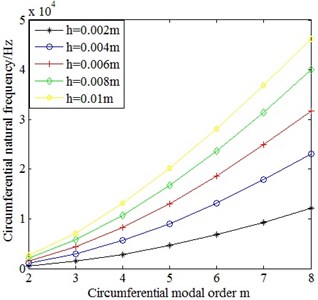
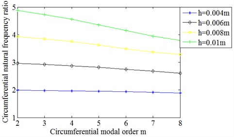
As displayed in Fig. 5, the circumferential natural frequencies of cylindrical shells have upward trend with the increase of wall thickness. In order to further analyze, the circumferential natural frequencies of cylindrical shells with different wall thickness are respectively divided by the circumferential natural frequencies corresponding to order of cylindrical shell with 0.002 m wall thickness. The results are illustrated in Fig. 6. According to Fig. 6, it shows that the ratio of circumferential natural frequencies of cylindrical shells with different wall thickness is approximately equal to the ratio of their wall thickness. Therefore, the circumferential natural frequencies of cylindrical shells have approximately linear relationship with their wall thickness. The expression is:
However, when the ratio of circumferential natural frequency is larger, with the increase of circumferential modal order, the ratio slightly declines.
Fig. 6Ratio of circumferential natural frequencies of cylindrical shells with different wall thickness to those of 0.002 m wall thickness
3.3. Influence of mean diameter on the circumferential natural frequencies of cylindrical shells
By keeping 0.144 m length and 0.004 m wall thickness of cylindrical shells unchanged, the mean diameter D of cylindrical shells is changed to investigate its influence on the circumferential natural frequencies of cylindrical shells. The material properties are shown in Table 1. The calculating results of FEM are described in Fig. 7.
Fig. 7Comparison on the circumferential natural frequencies of cylindrical shells with different mean diameter
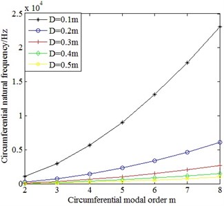
Fig. 8Ratio of circumferential natural frequencies of cylindrical shells with different mean diameter to those of 0.1 m mean diameter
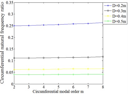
As can be seen from Fig. 7, the circumferential natural frequencies of cylindrical shells have upward trend with the decrease of mean diameter. In order to further analyze, the circumferential natural frequencies of cylindrical shells with different mean diameter are respectively divided by circumferential natural frequencies corresponding to order of cylindrical shell with 0.1 m mean diameter. The results are displayed in Fig. 8. The ratio of circumferential natural frequencies of cylindrical shells with different mean diameter are inversely proportional to the square of the mean diameter which can be observed in this figure. The expression is as follows:
However, with the increase of circumferential modal order, the ratio slightly rises.
3.4. Analytical calculation on the circumferential natural frequencies of cylindrical shells
The circumferential natural frequencies of cylindrical shell with 0.1 m length, 0.1 m mean diameter and 0.01 m wall thickness are calculated by Eq. (5) and Eq. (7). The material properties are shown in Table 1. The results calculated by analytical method and FEM are compared, as depicted in Table 2.
Table 2Comparison on the circumferential natural frequencies of cylindrical shell
Circumferential modal order m | Frequencies of Hoppe theory / Hz | Frequencies of Donnel-Mushtari theory / Hz | Frequencies of FEM / Hz | Relative errors of frequencies between Hoppe and FEM / % | Relative errors of frequencies between Donnel-Mushtari and FEM / % |
2 | 2549.3 | 2516.9 | 2526.4 | 0.91 | –0.38 |
3 | 7210.7 | 6004.7 | 6964.4 | 3.54 | –13.78 |
4 | 13826 | 10915 | 12908 | 7.11 | –15.44 |
5 | 22359 | 17236 | 19992 | 11.84 | –13.79 |
6 | 32801 | 24964 | 28036 | 17.00 | –10.96 |
7 | 45146 | 34097 | 36772 | 22.77 | –7.27 |
8 | 59394 | 44634 | 45859 | 29.51 | –2.67 |
9 | 75543 | 56571 | 55669 | 35.70 | 1.62 |
From Table 2, it can be seen that with the increase of circumferential modal order, the relative errors of frequencies between Hoppe theory and FEM are more and more larger, but the relative errors of frequencies between Donnel-Mushatari theory and FEM are reduced. In order to analyze the reasons, by comparing the change rate of respective frequencies to investigate the variation trend of frequencies, the results on change rate of frequencies are illustrated in Table 3.
Table 3Comparison on change rate of the circumferential natural frequencies of cylindrical shell
Circumferential modal order m | Change rate of frequencies of Hoppe | Change rate of frequencies of Donnel-Mushtari | Change rate of frequencies of FEM | Errors of change rate of frequencies between Hoppe and FEM | Errors of change rate of frequencies between Donnel-Mushtari and FEM |
3 | 2.83 | 2.39 | 2.76 | 0.07 | –0.37 |
4 | 1.92 | 1.82 | 1.85 | 0.07 | –0.03 |
5 | 1.62 | 1.58 | 1.55 | 0.07 | 0.03 |
6 | 1.47 | 1.45 | 1.40 | 0.07 | 0.05 |
7 | 1.38 | 1.37 | 1.31 | 0.07 | 0.06 |
8 | 1.32 | 1.31 | 1.25 | 0.07 | 0.06 |
9 | 1.27 | 1.27 | 1.21 | 0.06 | 0.06 |
As can be seen from Table 3, there is approximately linear relationship between the change rate of frequencies of Hoppe theory and that of FEM. With the increase of circumferential modal order of cylindrical shells, the errors of frequencies of Hoppe theory are increased in the form of accumulation, so the errors of frequencies are larger and larger. The differences between the change rate of frequencies of Donnel-Mushtari theory and that of FEM change from negative to positive, which make the relative errors between them fluctuate within a small range.
Through the above analysis, the variation trend of frequencies of Hoppe theory is more consistent with the actual situation. Therefore, the main reason which leads to the errors of change rate of frequencies of Hoppe theory should be analyzed. Based on the Eq. (5), the parameter which affects change rate of frequencies is the circumferential modal order m. Therefore, the curve of change rate of frequencies of Hoppe theory does not vary with the dimension parameters of cylindrical shells, which makes it have linear errors with the change rate of frequencies of FEM. Through the analysis of Section 3.1, it can be seen that the length has little influence on the circumferential natural frequencies of cylindrical shells, so the influence of length on their circumferential modes is excluded. According to the Eq. (5) and Eq. (7), Hoppe theory and Donnel-Mushtari theory do not contain the length parameter of the cylindrical shells. Although the Eq. (5) contains the length parameter l, I also contains l, the l of Eq. (5) has no effect on the calculating results of frequencies. From the analysis of Section 3.2, it shows that circumferential natural frequencies of cylindrical shells have approximately linear relationship with wall thickness. From the analysis of Section 3.3, it proves that the circumferential natural frequencies of cylindrical shells have inversely proportional relationship with the square of the mean diameter. If the influence of mean diameter and wall thickness of cylindrical shells on the circumferential natural frequencies of cylindrical shells is considered at the same time, it can be concluded that the diameter-thickness ratio of cylindrical shells has direct influence on variation trend of the circumferential natural frequencies of cylindrical shells.
3.5. Influence of diameter-thickness ratio on the circumferential natural frequencies of cylindrical shells
The curve of change rate of circumferential natural frequencies of cylindrical shells with different diameter-thickness ratio is depicted in Fig. 9. By comparing the change rate of circumferential natural frequencies of cylindrical shells with different diameter-thickness ratio, it shows that the change rate of circumferential natural frequencies of cylindrical shells has approximately linear relationship with the diameter-thickness ratio. The smaller the diameter-thickness ratio of cylindrical shells is, the lower the change rate of circumferential natural frequencies is. The higher the circumferential modal order is, the smaller the change rate of circumferential natural frequencies is.
Fig. 9Comparison on the change rate of circumferential natural frequencies of cylindrical shells with different diameter-thickness ratio
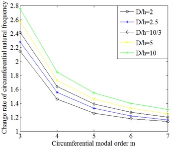
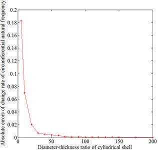
Therefore, when the diameter-thickness ratio of cylindrical shells is smaller, the differences between the change rate of frequencies calculated by Hoppe theory and that of FEM are larger. The Hoppe theory (Eq. (5)) is not suitable for the calculation of circumferential natural frequencies of cylindrical shells with the smaller diameter-thickness ratio. By changing the diameter-thickness ratio of cylindrical shells, the absolute errors between change rate of frequencies of Hoppe theory and that of FEM is described in Fig. 10.
As illustrated in Fig. 10, the curve is mainly divided into 3 changed regions. When the diameter-thickness ratio of cylindrical shells is greater than 90, the differences between the change rate of circumferential natural frequencies calculated by Hoppe theory and that of FEM are less than 0.001. When the diameter-thickness ratio of cylindrical shells is between 30 and 90, the differences between the change rate of circumferential natural frequencies calculated by Hoppe theory and that of FEM are less than 0.01. When the diameter-thickness ratio of cylindrical shells is less than 30, the differences between the change rate of circumferential natural frequencies calculated by Hoppe theory and that of FEM sharply increase. Therefore, it is necessary to adopt different calculating formulas to calculate the circumferential natural frequencies of cylindrical shells with different diameter-thickness ratio.
Fig. 10Absolute errors between the change rate of circumferential natural frequencies calculated by Hoppe theory and that calculated by FEM of cylindrical shells with different diameter-thickness ratio
When the diameter-thickness ratio of cylindrical shells is greater than 90, the Hoppe theory is adopted to calculate circumferential natural frequencies. When the diameter-thickness ratio of cylindrical shells is less than 90, by adding the parameter of diameter-thickness ratio of cylindrical shells to the Eq. (5), the improved formula for calculating the circumferential natural frequencies of cylindrical shells is obtained. When the circumferential modal order mis 2, the calculating formula is the same as the Eq. (5). When the circumferential modal order m is greater than or equal to 3, the formula is:
where:
When the diameter-thickness ratio of cylindrical shells is between 30 and 90, the influence coefficient of diameter-thickness ratio is:
When the diameter-thickness ratio of cylindrical shells is less than 30, the influence coefficient of diameter-thickness ratio is:
The improved formula is used to calculate the circumferential natural frequencies of cylindrical shell of Table 2. The results calculated by analytical method are compared with those calculated by FEM, as illustrated in Table 4.
Table 4Comparison on the circumferential natural frequencies of cylindrical shells calculated by improved formula and FEM
Circumferential modal order m | Frequencies of improved formula / Hz | Frequencies of FEM / Hz | Relative errors of frequencies between the improved formula and FEM / % |
2 | 2549.3 | 2526.4 | 0.91 |
3 | 7020.93 | 6964.4 | 0.81 |
4 | 12823.68 | 12908 | –0.65 |
5 | 19785.02 | 19992 | –1.04 |
6 | 27552.91 | 28036 | –1.72 |
7 | 35874.11 | 36772 | –2.44 |
8 | 44446.92 | 45859 | –3.08 |
9 | 53323.42 | 55669 | –4.21 |
As can be seen from Table 4, the results calculated by improved formula are significantly better than the results calculated by the Hoppe theory and the Donnel-Mushtari theory.
3.6. Influence of terminal box on the circumferential natural frequencies of cylindrical shells
A circular terminal box is added to the cylindrical shell. The influence of size and installation position of terminal box on the circumferential natural frequencies of cylindrical shells is analyzed.
(1) Influence of size of terminal box on the circumferential natural frequencies of cylindrical shells.
By keeping the 0.292 m length, 0.191269 m mean diameter, 0.010269 m wall thickness and 0m distance between the center of terminal box and the axial center of cylindrical shell unchanged, the radiusr of terminal box is changed to investigate its influence on the circumferential natural frequencies of cylindrical shells. The material properties are shown in Table 1. The calculating results of FEM are displayed in Fig. 11.
From Fig. 11, it can be seen that the circumferential natural frequencies of cylindrical shells with terminal box are bigger than the circumferential natural frequencies corresponding to order of cylindrical shell without terminal box, but the big or small of size of the terminal box has little influence on the circumferential natural frequencies of cylindrical shells. When the circumferential natural frequencies of cylindrical shells with terminal box are calculated, the stiffness correction coefficient due to the adding of the terminal box should be added. By least square fitting, σm is:
(2) Influence of installation position of terminal box on the circumferential natural frequencies of cylindrical shells.
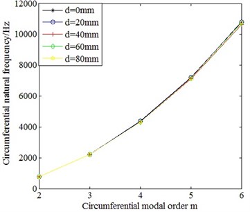
By keeping 0.292 m length, 0.191269 m mean diameter, 0.010269 wall thickness and 0.022 m size of terminal box of cylindrical shell unchanged, the distanced between the center of the terminal box and the axial center of cylindrical shell is changed to investigate its influence on the circumferential natural frequencies of cylindrical shells. The material properties are shown in Table 1. The calculating results of FEM are illustrated in Fig. 12.
From Fig. 12, it can be seen that the distance between the center of the terminal box and the axial center of cylindrical shell has little influence on the circumferential natural frequencies, that is, the circumferential natural frequencies of cylindrical shells do not vary with the distance between the center of the terminal box and the axial center of cylindrical shell.
Fig. 11Comparison on the circumferential natural frequencies of cylindrical shells with different size of terminal box
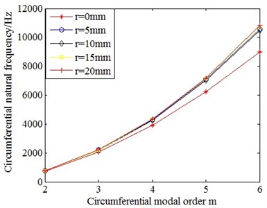
Fig. 12Comparison on the circumferential natural frequencies of cylindrical shells with different distance between the center of the terminal box and the axial center of cylindrical shell
4. Calculation on the circumferential natural frequencies of stator core and motor case
The analytical method and FEM are respectively adopted to calculate the circumferential natural frequencies of stator core and motor case. The results between analytical method and FEM are compared and the analytical formulas are modified.
(1) Calculation on the circumferential natural frequencies of stator core.
The improved formula Eq. (16) for calculating the circumferential natural frequencies of cylindrical shell is used to calculate the circumferential natural frequencies of stator core (Fig. 13(a)). The stator core is simplified as a cylindrical shell with the same length, outer diameter and volume, as shown in the Fig. 13(b). Due to the simplification of model, the stiffness error between the simplified cylindrical shell and the original model can be generated. Therefore, the stiffness correction coefficient of model simplification is added to the Eq. (16). The formulas are as follows:
For m= 2:
For m ≥ 3:
where:
Comparison on the calculating results between the analytical method (adopting the Eq. (22) and Eq. (23)) and FEM is shown in Table 5, and the material properties are displayed in Table 1.
Fig. 13Structural model of stator core
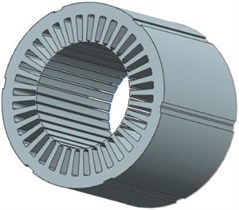
a) Original model
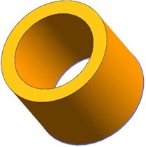
b) Simplified model
Table 5Comparison on the circumferential natural frequencies of stator core calculated by improved formula and FEM
Circumferential modal order m | Analytical frequencies / Hz | Frequencies of FEM / Hz | Relative errors of frequencies between analytical method and FEM / % |
2 | 776.06 | 772.09 | 0.51 |
3 | 2000.46 | 1953.7 | 2.39 |
4 | 3432.88 | 3417.6 | 0.45 |
5 | 4600.81 | 4600 | 0.02 |
6 | 5240.35 | 5284.1 | –0.83 |
According to the Table 5, the relative errors between the calculating results of improved analytical formula and those of FEM is within 2.39 %, so the correctness of Eq. (22) and Eq. (23) is verified.
(2) Calculation on the circumferential natural frequencies of motor case.
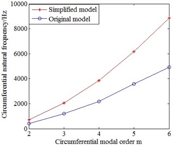
The motor case without terminal box is simplified as a cylindrical shell with the same inner diameter, length and volume. The circumferential natural frequencies of original motor case and the simplified cylindrical shell are calculated by FEM, and the comparison is depicted in Fig. 14. The material properties are shown in Table 6.
Table 6Material properties of motor case
ρ | E | v |
2800 | 7.17e10 | 0.33 |
From Fig. 14, it proves that there is error of circumferential natural frequencies between the original model and the simplified model. This is because the simplification of model make the stiffness change. The Eq. (16) should be added the stiffness correction coefficient of model simplification. By least square fitting, the stiffness correction coefficient of model simplification of motor case is:
Fig. 14Comparison on the circumferential natural frequencies between the simplified model and the original model of motor case
The actual motor case has terminal box (Fig. 15(a)). The simplified model (cylindrical shell) is displayed in Fig. 15(b). After considering the stiffness errors of existence of terminal box and model simplification, the analytical formulas are as follows:
For m= 2:
For m ≥ 3:
Fig. 15Structural model of motor case
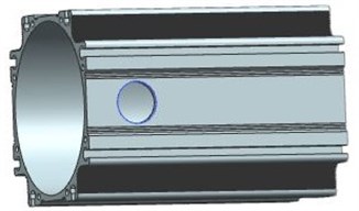
a) Original model

b) Simplified model
Table 7Comparison on the circumferential natural frequencies of motor case calculated by analytical method and FEM
Circumferential modal order m | Analytical frequencies / Hz | Frequencies of FEM / Hz | Relative errors of frequencies between analytical method and FEM / % |
2 | 414.12 | 434.48 | –4.69 |
3 | 1207.54 | 1298.2 | –6.98 |
4 | 2368.89 | 2373.8 | –0.21 |
5 | 3893 | 3933.8 | –1.04 |
6 | 5763.52 | 5792.8 | –0.51 |
By improved Eq. (26) and Eq. (27) and FEM, the circumferential natural frequencies of motor case are calculated, and the material properties are shown in Table 6. Comparison on the calculating results is illustrated in Table 7.
Based on the Table 7, the relative errors between the calculating results of improved analytical formula and those of FEM is within 6.98 %, so the validity of Eq. (26) and Eq. (27) is confirmed.
5. Experimental analysis
In order to validate the effectiveness of the above improved formula, the circumferential natural frequencies of stator structure (stator core, motor case, windings) (Fig. 16) is calculated by analytical method, FEM and experimental method. The material properties are shown in Tables 1, 6 and 8. The comparison on the calculating results is displayed in Table 9. When the analytical method is adopted, the stator structure is regarded as 5 coaxial thin-walled cylinders, that is, the stator core, motor core, slot windings, two end windings are respectively regarded as the thin-walled cylinders. The moment of inertia of synthesis of coaxial thin-walled cylinder is equal to the sum of moment of inertia of each thin-walled cylinder. Assuming that the lumped stiffness of the stator core, motor case, slot windings and end windings is parallel to each other, so the lumped stiffness of the stator structure is the sum of the five. For the lumped mass, the same equivalent method is adopted. Based on the above assumptions and the mutual constraints among the components of the stator structure, the analytical expression for calculating circumferential natural frequencies of stator structure is:
where calculating formulas of Mcm, Mfm, Muwm, Mlwm, Mswmare the same as the Eq. (3); calculating formula of Kcm is through the inverse derivation of Eq. (1), Eq. (3), Eq. (22) and Eq. (23); calculating formula of Kfm is through the inverse derivation of Eq. (1), Eq. (3), Eq. (26) and Eq. (27); calculating formulas of Kuwm, Klwm, Kswmare through the inverse derivation of Eq. (1), Eq. (3) and Eq. (16); the calculating formula for τm is as follows:
Fig. 16Structural model of stator structure
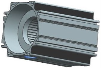
Table 8Material properties of the windings
Density of slot windings / (kg/m3) | Elastic modulus of slot windings / Pa | Poisson’s ratio of slot windings | Density of end windings / (kg/m3) | Elastic modulus of end windings / Pa | Poisson’s ratio of end windings |
5483.43 | 9.5e9 | 0.33 | 6223 | 1.95e10 | 0.33 |
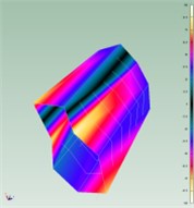
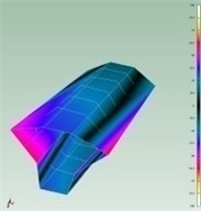
According to the modal test (Section 2.3), frequency response function of each testing point is summed, the natural frequency corresponding to each order of stator structure is analyzed and valued. Phase and amplitude of frequency response functions on some testing point are shown in Fig. 17. Fig. 18 is the comparison on the natural frequencies of different testing points (only extracting 10 testing points), and the natural frequencies on the Fig. 18 are the average value of natural frequencies corresponding to order of 10 testing points. In addition, Fig. 19 is the vibration mode shapes of stator structure obtained by experiment. The natural frequencies obtained by test are shown in Table 9.
Fig. 17Phase and amplitude of frequency response function of some testing point on stator structure
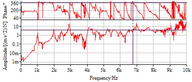
Fig. 18Natural frequency of some testing points on stator structure
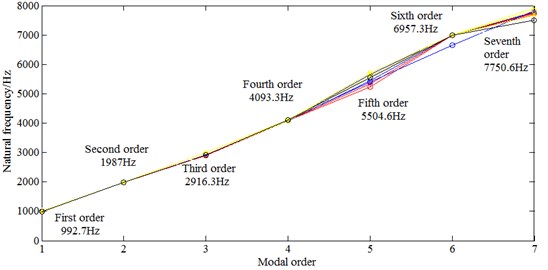
Fig. 19First six vibration mode shapes of stator structure obtained by experiment
a) First order mode
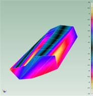
b) Second order mode
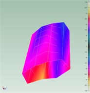
c) Third order mode
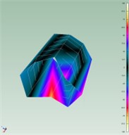
d) Fourth order mode
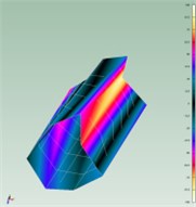
e) Fifth order mode
f) Sixth order mode
According to the Table 9, the relative errors of the calculating results of improved analytical formula with those of FEM and experimental method are respective within |4.43 %| and |3.38 %|. The effectiveness of above improved formula is verified.
Table 9Comparison on the circumferential natural frequencies of stator structure calculated by analytical method, FEM and experimental method
Circumferential modal order m | Analytical frequencies / Hz | Frequencies of FEM / Hz | Experimental frequencies / Hz | Relative errors of frequencies between analytical method and FEM / % | Relative errors of frequencies between analytical method and experiment / % |
2 | 1919.76 | 1974.6 | 1987 | –2.78 | –3.38 |
3 | 2873.71 | 2983.6 | 2916.3 | –3.68 | –1.46 |
4 | 3960.39 | 4143.9 | 4093.3 | –4.43 | –3.25 |
5 | 5347.75 | 5442.1 | 5504.6 | –1.73 | –2.85 |
6 | 6777.15 | 6732.3 | 6957.3 | –0.67 | –3.23 |
6. Conclusions
In this paper, through the analysis on the influence of length, wall thickness, mean diameter, diameter-thickness ratio, size and installation position of terminal box on the circumferential natural frequencies of cylindrical shells, the influence of stator core and motor case simplified as cylindrical shells on their circumferential natural frequencies, and calculation for the circumferential natural frequencies of stator structure with analytical method, FEM and experimental method, the following conclusions can be obtained:
1) The length of cylindrical shells has little influence on their circumferential natural frequencies, which can be neglected in calculation. The circumferential natural frequencies of cylindrical shells have approximately linear relationship with their wall thickness. However, when the ratio of circumferential natural frequency is larger, with the increase of circumferential modal order, the ratio slightly declines. The circumferential natural frequencies of cylindrical shells have inversely proportional relationship with the square of the mean diameter. But when the circumferential modal order increases, the ratio of circumferential natural frequencies slightly rises. The change rate of circumferential natural frequencies of cylindrical shells has approximately linear relationship with the diameter-thickness ratio. The smaller the diameter-thickness ratio of cylindrical shells is, the lower the change rate of circumferential natural frequencies is. The higher the modal order is, the lower the change rate of circumferential natural frequencies is. The existence of terminal box can improve the circumferential natural frequencies corresponding to order of cylindrical shells, but the big or small of size of terminal box has no effect on the circumferential natural frequencies of cylindrical shells with terminal box. The installation position of terminal box has almost no effect on the circumferential natural frequencies of cylindrical shells, which can be ignored in calculation.
2) The error of results gained by traditionally analytical formula increases as the diameter-thickness ratio decreases. For the sake of reducing error, a new analytical formula considering diameter-thickness ratio for calculating circumferential natural frequencies of cylindrical shells was developed. Compared with the results of FEM, the correctness of the analytical formula was verified. The stator core is simplified as a cylindrical shell with the same volume, length and outer diameter. The stiffness correction coefficient because of model simplification is added in the analytical formula which makes the error between the analytical results and results of FEM within |2.39 %|. The motor case is simplified as a cylindrical shell with the same volume, length and inner diameter. The stiffness correction coefficients due to model simplification and existence of terminal box are added in the analytical formula which makes the error between the analytical results and results of FEM within 6.98 %.
3) When the circumferential natural frequencies of stator structure are calculated by analytical method, a new analytical formula considering diameter-thickness ratio of stator structure, model simplification, existence of terminal box and mutual constraints among the components of stator structure is presented. Compared with the results of FEM and experimental results, the relative errors are respective within 4.43 % and 3.38 %, so the validity of the analytical method is confirmed.
References
-
Bianchini C., Immovilli F., Lorenzani E., et al. Review of design solutions for internal permanent-magnet machines cogging torque reduction. IEEE Transactions on Magnetics, Vol. 48, Issue 10, 2012, p. 2685-2693.
-
Tang Renyuan Modern Permanent Magnet Machines: Theory and Design. China Machine Press, Beijing, 2016.
-
Chen Yongxiao, Zhu Ziqiang, Ying Shancheng Analysis and Control of Motor Noise. Zhejiang University Press, Zhejiang, 1987.
-
Wang Tianyu, Wang Fengxiang Vibration and modal analysis of stator of large induction motors. Proceedings of the CSEE, Vol. 27, Issue 12, 2007, p. 41-45.
-
Mori D., Ishikawa T. Force and vibration analysis of induction motors. IEEE Transactions on Magnetics, Vol. 41, Issue 5, 2005, p. 1948-1951.
-
Gieras J. F., Wang C., Lai J. C. Noise of Polyphase Electric Motors. CRC Press, Boca Raton, 2006.
-
Wu Jianhua Study on the stator mode shapes and natural frequencies of switched reluctance motor based on real structural model. Proceedings of the CSEE, Vol. 24, Issue 8, 2014, p. 109-114.
-
Yu Shenbo, Tang Renyuan Electromagnetic and mechanical characterizations of noise and vibration in permanent magnet synchronous machines. IEEE Transactions on Magnetics, Vol. 42, Issue 4, 2006, p. 1335-1338.
-
Dai Ying, Cui Shumei, Song Liwei Finite element method modal analysis of driving motor for electric vehicle. Proceedings of the CSEE, Vol. 31, Issue 9, 2011, p. 100-104.
-
Wang C., Lai J. C. S. Prediction of natural frequencies of finite length circular cylindrical shells. Applied Acoustics, Vol. 59, Issue 4, 2000, p. 385-400.
-
Gan Lin, Li Xuebin, Zhang Heng Free vibration analysis of ring-stiffened cylindrical shells using wave propagation approach. Journal of Sound and Vibration, Vol. 326, Issues 3-5, 2009, p. 633-646.
-
Amabili M. A comparison of shell theories for large-amplitude vibrations of circular cylindrical shells: Lagrangian approach. Journal of Sound and Vibration, Vol. 264, Issue 5, 2003, p. 1091-1125.
-
Pellicano F. Vibration of circular cylindrical shells: Theory and experiments. Journal of Sound and Vibration, Vol. 303, Issues 1-2, 2007, p. 154-170.
-
Hoppe R. Vibrationen eines Ringes in seiner Ebene. Journal Für Die Reine Und Angewandte Mathematik, Vol. 73, 1871, p. 158-170.
-
Leissa A. Vibration of Shells. Acoustical Society of America, 1993.
-
Han Wei, Jia Qifen, Qiu Jiajun Vibration and modal analysis for stator of an induction motor. Journal of Vibration and Shock, Vol. 31, Issue 17, 2012, p. 91-94.
-
Yu Shenbo, Wang Weiqi, Zhong Shuangshuang, et al. Modal analysis of permanent magnet synchronous motorized spindle based on experimental and finite element method. Heavy Machinery, Vol. 5, 2016, p. 68-71.
-
Wu Hengzhuan Handbook of Common Materials for Motor. Shanxi Science and Technology Press, Xian, 2001.

