Abstract
The pull-in range of phase locked loop (PLL) is a key parameter for evaluating the performance of the PLL circuit. It is defined as the maximum detuning frequency range where the loop locks. Different methods have been proposed for computing the pull-in range of phase locked loops in the absence of time delay. In this paper, the effect of time delay on the pull-in range of second-order phase locked loop as well as its dynamical behavior will be discussed. The time delay is modeled using first order Pade approximation. Using Pade approximation, the nonlinear second order delay differential equation which describes the phase error dynamic of the PLL is transformed into fourth order system in the state space representation. The new time-delay PLL model is simulated and different behavior is observed which is different than a typical PLL system without delay. As the gain of the loop increases, new behavior such as change of circuit stability and chaos are recognized which suggests that the gain of the loop cannot be arbitrary large. We compare the pull-in range of a time delay PLL with those without time delay. Results demonstrate the degradation in the pull-in range for the time delay PLL. Moreover, result shows that the pull in range gets narrower as time delay increases.
1. Introduction
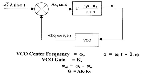
A phase-locked loop (PLL) is a feedback system that is used to maintain the phases of an output signal and a reference signal in a specific relationship. Phase-locked loops (PLL's) are used in many applications including frequency synthesis, demodulation, clock recovery and synchronization [1-3]. A PLL is used in a communication receiver to extract the modulated signal from a radio frequency carrier. This is accomplished by a PLL where the loop makes a voltage controlled oscillator (VCO) phase locking to the received input signal. The loop filter output will then contain the extracted FM signal, and the loop filter input will contain the PM signal. In this case the frequency response of the FM output will be a low-pass function described by the closed-loop transfer function and the PM output response will be a high-pass function described by the error function. In digital communications (modems) it is frequently necessary to extract a coherent clock signal from an input data stream. A PLL is often used for this task by locking a VCO to the input data and the data bits will be extracted from the input data by using the VCO output as a clock. Figure 1 shows the block diagram of the phase-locked loop (PLL) under investigation. It consists of three major parts: phase detector, VCO and low pass filter. The phase detector consists of a nonlinear device whose output is voltage proportional to the phase difference of the two input sinusoidal signals. The VCO is an electronic device that produces an output signal whose frequency is proportional to the input voltage. In this paper, we consider a second-order Type I PLL with sinusoidal phase detector characteristics. The PLL is driven by a sinusoidal signal with constant frequency of rad/sec, and the phase of the voltage controlled oscillator (VCO) is denoted as . The VCO’s instantaneous frequency is equal to , where and denote the VCO’s free running frequency and gain, respectively. The analog multiplier produces an error signal that is proportional to , where represents the closed loop phase error. The Loop filter is a low pass filter which processes the error signal and generates voltage which drives the VCO in an attempt to make small and hence control the PLL dynamics. The dynamical model of this PLL is developed in Section 2. The quantities and are a loop gain factor and the loop detuning, respectively and both of these parameters are assumed to be positive.
Fig. 1Second order phase locked loop
There are key parameters that specify the operation of a PLL such as damping factor which is a measure of the ability of the PLL to track an input signal step. Usually it is used to indicate the amount of overshoot present in the output to a step perturbation in the input. Loop gain is the combination of all DC gains in the PLL which is usually can be expressed as the product of two values. The first one is the phase detector gain which is the ratio of the DC output voltage of the phase detector to the input phase difference and has the unit of volts/radian. The second one is the VCO gain which is the ratio of the VCO output frequency to the DC control input level and has the unit of radians/second/volt. Other key parameters in the PLL design are the capture range, lock-in range, pull-out range and pull-in range. These parameters specify the frequency ranges in which the PLL can operate. Capture range is defined as the range of input frequencies over which the PLL can acquire phase lock (hold range). Lock-in range is defined as the range of input frequencies over which the PLL will remain in phase lock once acquisition has occurred. Pull-out range is defined as the dynamic limit for stable operation of PLL. Pull-in range is defined as the range that the PLL will always be locked. When it is locked, the dynamics obey mostly linear theory, and it is analyzed traditionally by using the transfer function. However, when it is out-of-lock or when it is in the process of locking, the dynamics become nonlinear and the various phenomena inherent to nonlinear systems such as complex bifurcations and chaos can occur in phase-locked loops [4] and analysis becomes fairly difficult.
Extensive work has been conducted for analyzing the pull-in range and the dynamical behavior of classical phase locked loops without time delay. These include harmonic balance technique, the phase plane method and numerical analysis [5-7]. The problem of determining the pull-in range of phase locked loops is solved indirectly by evaluating the limit cycles of the loop in which the frequency error has a constant average. Harb and Stensby [8] developed a Galerkin based algorithm for computing the PLL's half-plane pull-in range. Piqueira et al. [9, 10] analyzed the effect of the double-frequency term and phase jitter in the operation of the nonlinear second-order phase-locked loop (PLL). Through numerical simulations, they confirm the dependence of oscillation on the PLL gain. Later, Piqueira [11] determined the lock in range for a third-order PLL analytically by identifying saddle-node and Hopf bifurcations. The work by Harb and Harb [13] showed that a third-order phase-locked loop (PLL) with sinusoidal phase detector characteristics experienced a Hopf bifurcation point as well as chaotic behavior. Later, they designed a nonlinear controller based on the theory of backstepping to control the chaotic behavior of the PLL [14]. On the other hand, Bradley and Straub [15] used chaos to broaden the capture range of phase locked loop. In the work of Endo et al. [16], chaos from PLL based frequency modulators was reported in the condition when the carrier frequency of the FM signal was outside the locked state of the PLL.
Time delay is an unavoidable in certain applications of phase locked loops such as in the case of radio reception. Recently, many studies have been carried out to under-stand the causes of dynamic instabilities in phase locked loops. Time delay which is considered lumped in the predetection IF amplifier and/or a radio frequency interference rejection filter at the VCO output is found to be a major factor that causes dynamic instability in PLL. Analysis of nonlinear systems with time delays is extended from the knowledge available for standard nonlinear systems without delays and using some methods to approximate the delay like the Pade approximation method and harmonics approximation. Schanz and Pelster [17] proved the existence of a Hopf bifurcation in first order PLL with time delay using the method of multiple scale. Buckwalter and York [18] found an optimal gain that minimize the acquisition time for time-delay high frequency phase locked loop. Grant et al. [19] investigates the performance of optical phase-locked loops in the presence of non negligible loop propagation delay.
Time delay can generate instabilities in a PLL under certain gain and frequency detuning conditions. Consequently, the effect of time-delay on pull-in and hold-in range is a design constraint. The results of [18] indicate that increasing the loop gain improves both the pull-in and hold-in ranges for a second order phase locked loop. However, in this paper, analysis demonstrates that gain cannot be arbitrarily large to guarantee the pull-in process. This paper motivation is to highlight fundamentally different dynamical behavior in a second-order PLL due to loop time delay than is typically presented and how this time delay affect the pull-in range of the PLL under consideration. The analysis of the PLL is based on circuit parameters such as gain, time delay, poles and zeros of the filter and frequency detuning. Pade approximation will be used to approximate the time delay component in deriving the state space representation of a second-order phase locked loop with sinusoidal phase detector characteristics.
The paper is organized as follows: Section 2 illustrates the derivation and analysis of the PLL under consideration without time delay. Section 3 contains the dynamical model and derivation of state space representation of second order PLL with time delay. Simulation of the delay model and results will be presented in Section 4. In section 5 conclusions are drawn based on the analysis of the simulations.
2. Analysis of second-order PLL without delay
The PLL model depicted in Figure 1 has a closed loop phase error which satisfies:
where is a function of time [7]. and are assumed to be positive and .
Define the two state variables , as:
Eq. (1) can be written in state space representation as:
The desired behavior of the second order PLL is phase locking. Mathematically, this behavior corresponds to solutions such that and . Solving Eq. (3) we get the equilibrium points given by:
The eigenvalues of the Jacobian matrix determine the local stability of the equilibrium points. The Jacobian matrix associated with the second order PLL is determined to be:
Evaluating the Jacobian matrix at the equilibrium point given by Eq. (4) yields:
and the corresponding characteristic equation is given by:
It is was verified that for values of , Eq. (7) has two eigenvalues of opposite sign which indicates that the equilibrium point is a saddle type and hence a separatrix cycle (saddle-to-saddle connection) exists. The PLL under consideration is in phase-locked when the phase error is constant, and a stable equilibrium condition exists. It is well known that phase lock is possible (but may not be achieved when the loop is closed) for [7, 8]:
The frequency is known as the PLL’s hold in range. Finally, no stable equilibrium points exist, and phase lock is cannot happen for . Under condition (8), it is known that the PLL’s state vector must approach (as ) a stable limit cycle with:
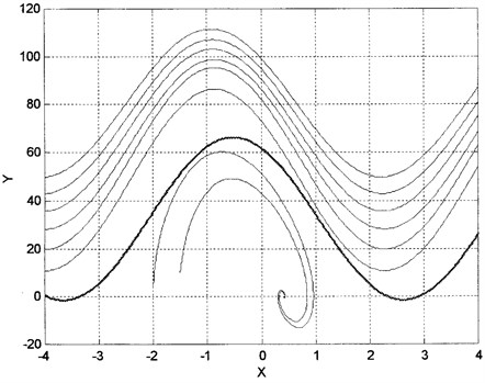
where is periodic function with fundamental frequency of [8]. This limit cycle is known as a stable false lock state [7]. This state corresponds to a periodic solution of the nonlinear differential equation describing the PLL. The PLL’s pull-in range is one of the main parameters in practical applications of phase locked loops. As positive decreases, a point , , is reached where bifurcates, and phase lock occurs. No false lock state (limit cycles) exist for , and the PLL will pull in (i.e., achieve phase lock) regardless of the initial conditions when the loop is closed. This is based on the fact that a separatrix cycle terminates the PLL's stable limit cycle associated with the false lock state as detuning parameter decreases through the pull-in value (bifurcation point). Figure 2 is a typical phase plane plot which indicates the case where bifurcates directly from an externally stable separatrix cycle (dark line). The plot was computed for a PLL containing a loop filter with , and . Note that and .
Fig. 2Bifurcation of a limit cycle from a separatrix cycle (dark line) as ωos decreases
3. Derivation and analysis of the PLL with delay
Consider Figure (3) which represents the block diagram for second-order delay phase-locked loop.
Fig. 3Second order delay phase locked loop
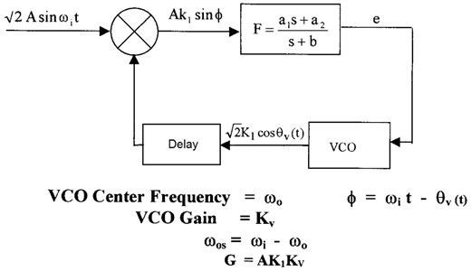
The equation of the second order system with feedback time delay is given by:
Define the four state variables , , and as:
In order to write the above equations in state space representation, the first order Pade approximation will be used for the delay operator. Note that Eq. (11) can be written as:
Substitute these state variables in Eq. (10) to get:
By using the first order Pade approximation [20]:
We obtain:
Substitute Eq. (13) into Eq. (15) to get:
It is obvious now that the time delay inherent in the PLL doubles the system order and the second order system becomes a fourth order system. The state space representation of the second order PLL with delay is given by:
The equilibrium point is given by setting in Eq. (17). By doing so, one obtains:
The local stability of the system can be checked based on the Jacobian matrix given by:
where , , .
Substitute and to evaluate the Jacobian matrix around the equilibrium point to get:
Define the constant:
Solve det to get the following characteristics equation:
where , , .
4. Simulation of the delay model
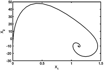
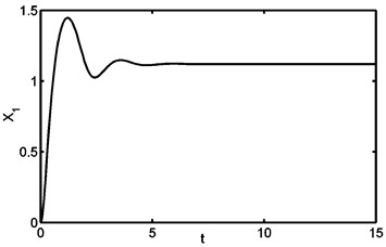
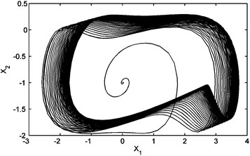
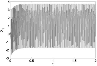
The system given by Eq. (17) is simulated using MATLAB fixed value of time delay and different values of gain. The values of , and are fixed throughout the simulation. Figure (4) shows that the system is in phase lock state for 100 K. Increasing in , the system exhibits a chaotic behavior as shown in Figure (5). This behavior starts at 20 K and the system remains in this regime up to 60 K. This range is wider than that in the first order PLL [17] which makes it more efficient to be used as chaos generator.
Fig. 4(a) Phase plane trajectory (equilibrium solution) for G= 100 K and τ = 0.002 sec; (b) time domain history for G= 100 K and τ = 0.002 sec
(a)
(b)
Fig. 5(a) Phase plane diagram (chaotic behavior) for G= 60 K and τ= 0.002 sec; (b) time domain history for G= 60 K and τ= 0.002 sec
(a)
(b)
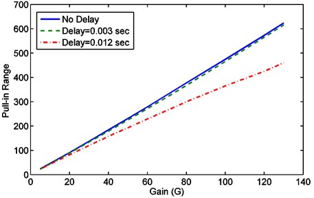
In order to study the effect of time delay on the pull-in range, Eq. (17) is simulated for different values of delay and gain. For a fixed values of delay () and gain (), the pull-in range is determined by finding the value of – where the system given by Eq. (17) changes its stability from equilibrium state (phase-lock state) to a periodic solution (out-of-lock) state as changes. These results are summarized in Table (1) below. Figure (6) shows the pull-in range of a second-order phase locked loop without delay and with delays of 0.003 sec and 0.012 sec. The figure shows clearly the degradation in the pull-in range due to time delay. Furthermore, it demonstrates that as the time delay increased, the pull-in range gets narrower. For these plots, the values of , and are used.
Table 1Gain versus the pull in range for different values of delay
Pull in range (0.012 sec) | Pull in range (0.003 sec) | Pull in range No delay | )Gain) |
23 | 23 | 24 | 5 |
82 | 89 | 91 | 20 |
120 | 134 | 137 | 30 |
158 | 179 | 183.5 | 40 |
193 | 225.5 | 231 | 50 |
229 | 272 | 279 | 60 |
264 | 319 | 328 | 70 |
300 | 367 | 377 | 80 |
365 | 466 | 474 | 100 |
425 | 565 | 573 | 120 |
460 | 616 | 624 | 130 |
Fig. 6Pull-in range vs. gain for second order phase locked loop
5. Conclusions
New results concerning the pull-in range of delay phase locked loop are reported. The effect of time delay on the pull-in range of second-order phase locked loop as well as its dynamical behavior are presented. First order Pade approximation is used to model the time delay element which is presented in the loop. By using Pade approximation, the nonlinear second order delay differential equation which describes the phase error dynamic of the PLL is transformed into fourth order system in the state space representation. This time-delay PLL model is simulated and different behavior is observed which is different than a typical PLL system without delay. As the gain of the loop increases, new behavior such as change of circuit stability and chaos are recognized which suggests that the gain of the loop cannot be arbitrary large. The pull-in range of a time delay PLL is compared with those without time delay. Results showed that the pull-in range for the time delay PLL is narrower than PLL without delay. Moreover, result shows that the pull in range gets narrower as time delay increases. Also, it is found that for delay phase locked loop the degradation of the pull-in range becomes more noticeable as the closed loop gain increased and this needs to be investigated in future work.
References
-
Stensby John L. Phase-locked loops: theory and applications. CRC Press, USA, 1997.
-
Gardner Floyd M. Phaselock techniques. Wiley-Interscience, New Jersy, USA, 2005.
-
Meyr H. A., Ascheid G. E. Synchronization in digital communications. New York: John Wiley & Sons, 1990.
-
Endo T., Chua L. Chaos from phase-locked loops. IEEE Transactions on Circuits and Systems, Vol. 35, Issue 8, 1988, p. 987-1003.
-
Endo T., Tada K. Analysis of the pull-in range of phase-locked loops by the galerkin procedure. Electronics and Communications in Japan, Part I: Communications, Vol. 69, Issue 5, 1986, p. 90-98.
-
Lindsey W. C. Synchronization systems in communication and control. Prentice Hall, Englewood Cliffs, New Jersey, 1972.
-
Stensby J. L., Harb B. Computing the half-plane pull-in range in a second-order phase locked loop. IEE Electronics Letters, 1995, p. 845-846.
-
Harb B., Stensby J. The half-plane pull-in range of a second-order phase-locked loop. Journal of Franklin Institute, Vol. 333B, Issue 2, 1996, p. 191-199.
-
Piqueira J. R. C., Takada E. Y., Monteiro L. H. Analyzing the effect of the phase-jitter in the operation of second order phase-locked loops. IEEE Transactions on Circuits and Systems II – Express Briefs, Vol. 52, Issue 6, 2005, p. 331-335.
-
Piqueira J. R. C., Monteiro L. H. Considering second-harmonic terms in the operation of the phase detector for second-order phase-locked loop. IEEE Transactions on Circuits and Systems I, Vol. 50, Issue 6, 2003, p. 805-809.
-
Monteiro L. H., Favaretto D. N., Piqueira J. R. C. Bifurcation analysis for third-order phase-locked loops. IEEE Signal Processing Letters, Vol. 11, Issue 5, 2004, p. 494-496.
-
Piqueira J. R. C. Using bifurcations in the determination of lock in ranges for third-order phase-locked loops. Commun Nonlinear Sci Numer Simulat, Vol. 14, 2009, p. 2328-2335.
-
Harb B. A, Harb A. M Chaos and bifurcation in a third-order phase locked loop. Chaos, Solitons & Fractals, Vol. 19, Issue 3, 2004, p. 667-672.
-
Harb A. M., Harb B. A. Chaos control of third-order phase locked loops using backstepping nonlinear controller. Chaos, Solitons & Fractals, Vol. 20, Issue 4, 2004, p. 719-723.
-
Bradley E., Straub E. Using chaos to broaden the capture range of phase-locked loop: experimental verification. IEEE Trans. on Circuits and Systems, Vol. 43, Issue 11, 1996, p. 914-922.
-
Endo T., Chua L. O. Chaos from phase-locked loops. IEEE Transactions on Circuits and Systems, Vol. 35, 1988, p. 987-1003.
-
Schanz M. I., Pelster A. X. Analytical and numerical investigation of the phase–locked loop with time delay. Journal of Chaos, Solitons and Fractals, Vol. 11, 2005, p. 142-148.
-
Buckwalter J. A., York R. A. Time delay considerations in high-frequency phase-locked loop. IEEE RFIC Conf., 2000, p. 181-184.
-
Grant M. A., Michie W. C., Fletcher M. The performance of optical phase-locked loops in the presence of non negligible loop propagation delay. J. Lightwave Technology, Vol. 5, 1987, p. 592-597.
-
Franklin G. F., Powell J. D., Emami-Naeini A. Feedback control of dynamic systems. 3rd ed., MA: Addison Wiley, 1994.
