Abstract
The use of tap water instead of the conventional hydraulic fluids in power-control hydraulics is one of possible environmentally friendly changes that we can make. In this paper we show, based on dynamic-transient parameters, both the functionality and the usability of water hydraulics in comparison to the more familiar oil hydraulics. A comparison of the dynamic behavior, oriented to pressures, between the conventional mineral hydraulic oil and the relatively new water hydraulics under the same conditions is described here. The tests were made at different flow rates (11, 22 and 33 lpm), different system pressures (70, 110 and 160 bar) and with different loads (first with a mass of 163 kg in the horizontal and vertical positions and second without this mass). Different dynamic characteristics during the pressure-surge effect of water and oil hydraulics were observed. The pressure increases were between 10 and 30 % higher in the water hydraulics than in the oil hydraulics. The frequencies of the pressure oscillations were up to 20 % lower in the water hydraulics than in the oil hydraulics.
1. Introduction
Despite being environmentally friendly, water hydraulic systems are not involved in many applications. When we talk about water hydraulics, we are referring to the use of tap water without any additives for the hydraulic fluid instead of conventional hydraulic fluids that can harm the environment.
Interestingly, it was water that was the first fluid used in industrial power-control hydraulics, more than two hundred years ago [1]. However, in the early years of water hydraulics there were many problems associated with both durability and functionality.
During the 19th Century, after the oil industry began to develop [2, 3], there was no further use of water hydraulics. Oil-based hydraulic machines worked better and for longer time than the equivalent water hydraulic machines. The reasons for the replacement of water hydraulics were linked to the low volumetric and mechanical hydraulic efficiencies, corrosion and high wear for the materials known at that time.
However, mineral hydraulic oil is not the best solution. The main problem is related to polluting the natural environment and in particular to the spoiling of drinking water. One so-called “soft” solution is to use a bio-degradable hydraulic oil [4-9], but the problem is with the additives, which tend not to be totally degradable. For this reason, in the early 1990s, many countries [2, 10-14] began with research into the possibilities of using tap water as a hydraulic fluid.
On this place it is convenient also to mention the use of pneumatics instead of mineral oil hydraulics when we need only lower working forces [11-13]. For such cases it is especially environmentally suitable when we use bio-oil as lubricant or particularly when we use unlubricated compressed air, for which the components are already some decades available on the market for the field of industrial pneumatics.
The current situation on the market is that the available water hydraulic components are not persuading customers that they can replace oil-based systems and so lead to a significant increase in use [10].
In this paper we would like to show that water hydraulics can work as well as the familiar oil hydraulics. In order to do this a combined oil and water hydraulic test rig was designed and constructed [15, 16]. A new water proportional 4/3 directional control valve was designed and long-term tests were conducted [17].
In terms of stationary behavior, the most important functional working characteristics were examined and compared with those of oil hydraulics [18]. Stationary characteristics of both types of hydraulic systems concerning pressure were compared, and these characteristics show the basic functionalities of both the water and oil hydraulic systems.
The dynamic characteristics of water power-control hydraulics concerning pressure were examined and compared with the characteristics of oil hydraulics. In this paper we show different dynamic pressure characteristics of water-based and similar oil-based power-control hydraulics.
The aim of the paper is also to show the difference in the behaviour between water and oil power-control hydraulics and to present a relatively simple mathematical model that enables us to calculate and predict some important parameters during the pressure changes at transient phenomena, using either water or mineral oil as the hydraulic fluid. Especially important are changes of pressure when pressure oscillations occur. It is important to predict the critical parameters – pressures during the design phase of the hydraulic system for either water or oil.
2. Testing device
2.1. Test rig
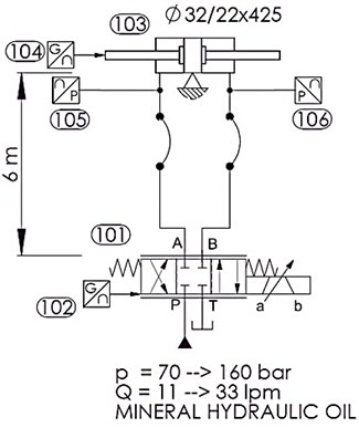
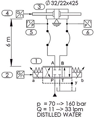
The combination test rig, with one part of it for investigating water power-control hydraulics (PCH) and the second part for investigating the compared oil PCH, was constructed and used for the experimental investigations [15, 16, 18]. This combination test rig was also used to test and investigate the water and oil valves, with both valves being of the proportional 4/3 directional spool-sliding control type (Fig. 2(b)). The same test rig was used to carry out comparative stationary [18], dynamic-transient (this paper) and static-long-term life-time tests [19] under the same, or at least analogous, working conditions. Figure 1 shows a simplified hydraulic circuit used for the dynamic tests of the oil (Fig. 1(a)) and water parts (Fig. 1(b)) of the test rig. The water hydraulic test rig contains a hydraulic power pack and a cooling-filtration unit (not shown in Fig. 1) [18], and a newly designed water proportional directional control valve [15, 16] (Fig. 1(b), pos. 1) with a linear variable differential transformer (Fig. 1(b), pos. 2). The proportional valve was controlled from a PC in a closed loop. To the connection port A of the proportional valve, we connected a 3-m stainless-steel tube (Ø12x1.5 mm) and a 3-m flexible tube, to which a pressure transmitter (Fig. 1, pos. 5) and a double-acting hydraulic cylinder (Fig. 1, pos. 3) were connected at the end. The second branch on the connection B was the same. A roller-guided load-mass of 163 kg (Fig. 3(b) and Fig. 3(d)) was connected to the rod of the hydraulic cylinder in the vertical or horizontal position, depending on the type of measurement. A centrifugal water pump, a temperature transmitter and an additional 1-μm by-pass filter were used to maintain a constant temperature and to enable high-quality off-line filtering [15, 16]. The pressures on the A and B connection ports of the water proportional valve were measured during the test using a pressure transmitter (Fig. 1, pos. 5 and 6). The control of the proportional solenoids (Fig. 1, pos. 1), the data acquisition and the electro-motors were automated with the PC.
The oil part of the hydraulic test rig is equivalent to the water test rig, in terms of function, but it is assembled using standard, commercially available components.
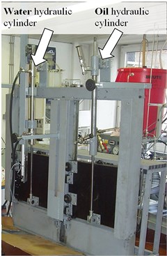
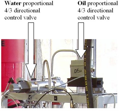
The water hydraulic test rig (Fig. 1(b) and Fig. 2) is assembled from standard, commercially available, water hydraulic components, except for the proportional 4/3 directional control valve (Fig. 1(b), pos. 1 and Fig. 2(b)) and the hydraulic cylinder (Fig. 1(b), pos. 3 and Fig. 2(a)). These two components were designed in our Laboratory for Power-Control Hydraulics (LPCH). The tubes for the water and the oil hydraulic cylinders were made from stainless steel and the rod was made from hard-chromium-plated steel. The seals and guide rings for both hydraulic cylinders are the same; they were made from nitrile rubber, polyurethane, and a fabric-based laminate. The oil part of the test rig (Fig. 1(a)) was the same in terms of function. It is assembled from standard components, except for the hydraulic cylinder. The developed oil hydraulic cylinder (Fig. 2(a)) is typical for oil hydraulic applications. It has the same design, the same dimensions and the same surface properties as the water cylinder. A photograph of the water and oil hydraulic cylinder with loads (mass of 163 kg) is shown in Fig. 2(a). Figure 2(b) shows the new water proportional 4/3 directional control valve [15, 16] and the standard oil proportional 4/3 directional control valve.
Fig. 1Simplified hydraulic circuit for measurements of the dynamic characteristics of a) the oil and b) the water hydraulics
(a)
(b)
Fig. 2a) Photograph of the water and oil hydraulic cylinder with a load of 163 kg in the vertical position, b) photograph of water and oil proportional 4/3 directional control valve
(a)
(b)
2.2. Experimental procedure and testing parameters
The whole testing procedure was fully automated with the PC software [16]. All the presented results were measured using the same procedure.
The parallel-shaped position of the proportional 4/3 directional control valve (Fig. 1(a), pos. 101 and Fig. 1(b), pos. 1) was first switched on and the hydraulic cylinder rod, after a short time acceleration, moved with constant velocity. The working pressures on ports A and B of the valve (Fig. 1(a), pos. 105 and 106 and Fig. 1(b), pos. 5 and 6) were, during constant velocity movement, therefore stable-constant, without any larger disturbances. After sometime with these constant circumstances the proportional directional valve instantaneously switched into the zero-blocked position. Whereupon the flows through all four ports of the valve were closed. The closing of the flow-gaps in the valve lasted only approximately 10 ms. Immediately after closing of the valve the pressure-surge effect occurred.
The measurements were performed with and without the load mass of 163 kg. This load mass was differently positioned (Fig. 3), once in the horizontal (Fig. 3(c) and Fig. 3(d)) and once in the vertical direction (Fig. 3(a) and Fig. 3(b)). The tests were made with three different flows (11, 22 and 33 lpm) and three different pressures settings of 70, 110 and 160 bar.
The same experimental procedure was used in both hydraulic circuits, once with water and secondly with oil. In the water hydraulic test rig we used distilled water and in the oil hydraulic test rig we used ISO VG 46 mineral hydraulic oil. The working temperatures of the fluids in both test rigs were maintained, through cooling, at 40°C+/–2°C.
All of the presented measurements were repeated at least three times.
Fig. 3Different positions and loads used during the measurements a) without vertical mass, b) with vertical mass, c) without horizontal mass and d) with horizontal mass
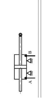
(a)
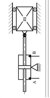
(b)
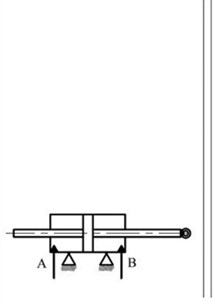
(c)
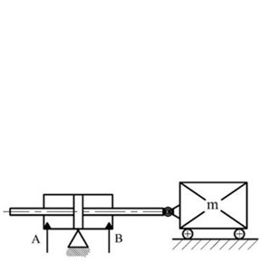
(d)
3. Mathematical validation
The change in the rate of motion of an energy-carrying hydraulic fluid and within it of the actuator, within a given time interval, involves the acceleration and/or deceleration of that motion and of the moving masses, depending on that motion through the hydraulic fluid. The final applicable equations for the flow and the pressure changes over time, at an instant, or for gradual changes of the fluid and the actuator’s velocity can be derived from a basic equation [20]. These equations are identical for accelerations and decelerations. Yet in practice, for machines using hydrostatic drives, the decelerations are normally more problematic than the accelerations. Therefore, our experiments were focused mostly on decelerations. In particular, the instant stopping of movements can cause oscillations, as a result of which heavy damage to a machine’s construction can occur because of the additional mass-inertia forces. However, when the resistance to motion is low enough, the actuator with the associated masses undergoes oscillatory damped movements. Deriving the basic equation, considering the conditions for underdamped oscillations, and furthermore considering that the valve closing that stops the fluid flow is so quick that it could be considered as instantaneous, we obtain the following equation (Eq. (1)) for the pressure variations over time [20]:
In this above equation, represents the constant flow during the actuator’s movement with a constant velocity before the deceleration or after the acceleration period, represents the resistance of the moving masses to this acceleration and represents the coefficient of the resistance to motion. However, it should be mentioned that some simplifications were used when deriving this basic equation. The coefficient of friction and some other values were considered to be constant during the deceleration, though they are not really constant. Otherwise, the derivation would be far too mathematically complicated. We wanted to come up with a mathematical model that was not necessarily very exact, but could be easily usable.
Figure 4 shows the results of the mathematical validation (Eq. 1) of the pressure changes during the pressure-surge effect for similar parameters to those in the presented test rigs for the case of a hydraulic cylinder with a load (163 kg) in the horizontal position. The maximum pressure amplitude with the water was 260 bar and with oil it was 168 bar. The time period of the pressure oscillation was 83 ms (12 Hz) in the water hydraulics and 113 ms (8.8 Hz) in the oil hydraulics.
Fig. 4Simulated pressure change (Eq. (1)) over time during the instantaneous stopping of a moving load (mass of 163 kg in horizontal position) for water and oil hydraulics
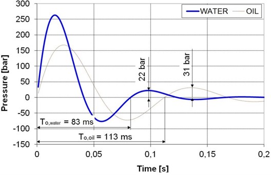
Fig. 5Simulated pressure change (Eq. (1)) over time during the instantaneous stopping of a moving cylinder rod without additional load for water and oil hydraulics
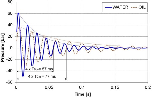
Figure 5 shows the results of the mathematical validation (Eq. (1)) of the pressure changes during the pressure-surge effect for the case of a hydraulic cylinder without any load (considering only the weight of the moving cylinder rod, 5 kg). The maximum pressure amplitude with the water was 61 bar and with oil it was 38 bar. The time period of the pressure oscillation was 14.3 ms (70 Hz) in the water hydraulics and 19.3 ms (52 Hz) in the oil hydraulics.
4. Experimental results
4.1. Pressure increase during the pressure-surge effect
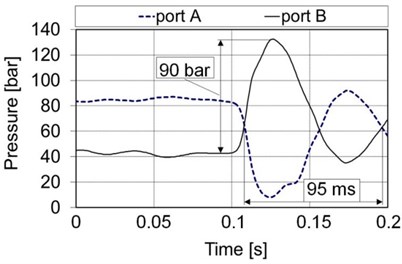
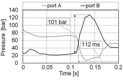
Figure 6 shows the results of pressure measurements during the pressure-surge effect for instantaneous closing of the proportional 4/3 directional control valve. The measurements were made with a mass of 163 kg in the horizontal position at a flow of 33 lpm and an inlet pressure of 160 bar on the P port of the valve. The pressures were measured on both sides of hydraulic cylinder (Fig. 1, for water test rig: pos. 5 and 6, for oil test rig: pos. 105 and 106). The pressure-surge effect occurred mainly because of the deceleration of the well-guided mass (163 kg) and partly as a result of the decelerating of the fluid column in the tubes.
Figure 6(a) shows the measured pressure changes during the instantaneous closing of the oil flow through the oil proportional 4/3 directional control valve. The stationary pressure at port B before closing the oil proportional valve was approximately 43 bar, and after closing the valve the absolute pressure on this port was 133 bar. Fig. 6(a) shows a relative pressure increase on port B of 90 bar after switching the oil valve from the working (open) to the neutral (closed) position.
The stationary pressure on port B before the closing of the water 4/3 directional control valve (Fig. 6b) was approximately 26 bar; however, after closing it increased to 127 bar. The relative pressure increase of 101 bar due to the pressure-surge effect in the water hydraulic test rig was detected on the valve B port.
Fig. 6Results of measuring the pressures during the pressure-surge effect on the A and B ports of the proportional 4/3 directional control valve for the instantaneously closed valve; a) oil hydraulics, b) water hydraulics (flow= 33 lpm, inlet pressure= 160 bar, load= 163 kg in horizontal position)
(a)
(b)
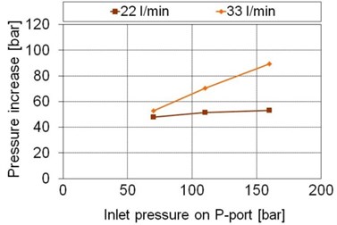
Figure 7(a) shows the influence on the pressure increase for different inlet pressures (70, 110 and 160 bar) and two different flows (22 and 33 lpm) through the oil proportional 4/3 directional control valve on the pressure increase (amplitude) during the pressure-surge effect resulting from the instantaneously closed valve. The lowest pressure difference on the oil hydraulic test rig was 48 bar, for an inlet pressure of 70 bar and a flow of 22 lpm. The highest pressure difference in the oil hydraulic test rig, 90 bar, occurred at an inlet pressure of 160 bar and a flow of 33 lpm.
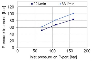
Figure 7(b) shows the influence of pressure increases at different inlet pressures (70, 110 and 160 bar) and different flow rates (22 and 33 lpm) through the water proportional 4/3 directional control valve during the pressure-surge effect. The lowest pressure difference on the water hydraulic test rig was 52 bar, at an inlet pressure of 70 bar and a flow of 22 lpm. The highest pressure difference in the water hydraulic test rig, 101 bar, occurred at an inlet pressure of 160 bar and a flow of 33 lpm.
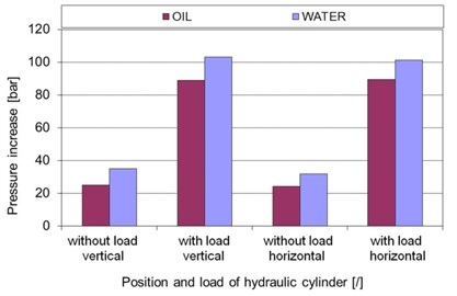
Figure 8 shows the influence on the pressure increases for port A of the valve (and of the cylinder too) at two different positions and two different loads of the water and oil hydraulic cylinders during the pressure-surge effect (See also Fig. 4 and Fig. 1). We observe pressure surge effect which proceeds at the instant when switching the directional valve from left (cross) position to neutral position. The piston was about in the middle of the stroke. The inlet flow was 33 lpm and the system pressure was 160 bar. The lowest pressure increase in the oil hydraulic system, 24 bar, occurred in the case of an unloaded oil hydraulic cylinder in the horizontal position. Measurements of the hydraulic surge effect with a load (mass of 163 kg) indicated that the pressure increases in the horizontal and vertical positions of the oil hydraulic cylinder were the same, i.e., approximately 89 bar.
The lowest pressure increase in the water hydraulic system (Fig. 8), 32 bar, occurred on A port of the water hydraulic cylinder without any load in the horizontal position. The highest pressure increase in the water hydraulic test rig, 103 bar, occurred in the vertical position of the water hydraulic cylinder with a load (mass of 163 kg). In this case in the water hydraulic test rig there was a pressure increase of the loaded hydraulic cylinder in the vertical position that was 2 bar higher than in the case of the loaded water cylinder in the horizontal position.
These measurements of the pressure-surge effect showed that the main influence on the pressure increase has the weight of the load. The influence of the position of the load was found to be insignificant.
Fig. 7Pressure increases during the pressure-surge effect on the B port (the same passes for A port) of the proportional 4/3 directional valve as a response to an instantaneously closed valve for the known flow and inlet pressure; a) oil, and b) water (loading mass= 163 kg in the horizontal position)
(a)
(b)
Fig. 8Pressure increases for the oil and water hydraulics during the pressure-surge effect on the A port of the proportional 4/3 directional valve in response to an instantaneously closed valve for different positions of the cylinder and different loads (flow= 33 lpm, pressure= 160 bar)
4.2. Pressure oscillating frequency during the pressure-surge effect
An example of the measurements of the pressure oscillations after the pressure-surge effect is shown in Fig. 6. The pressure-oscillating period for an inlet flow of 33 lpm, a system pressure of 160 bar and a loaded hydraulic cylinder in the horizontal position was 95 ms (approx. 10.5 Hz) in the oil hydraulic system. In the adequate water hydraulic system the period of the pressure oscillations was 112 ms (approx. 8.9 Hz). In the water hydraulic system it is possible to observe a non-smooth shape of pressure oscillations. As a result of this it was sometimes hard to determine correctly the tops of the curves.
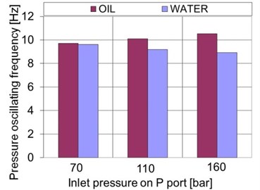
Figure 9(a) shows the pressure oscillating frequency response to an instantaneously closed valve for three different inlet pressures at inlet flow of 33 lpm in the oil and water hydraulic cylinders.
It is evident that the pressure-oscillating frequency in the oil hydraulics gradually increases with the system pressure; however, in the water hydraulics it decreases with an increase of the system pressure. The highest pressure-oscillating frequency in the oil hydraulics was 10.5 Hz at 160 bar, and the lowest was 9.7 Hz at a system pressure of 70 bar. The highest pressure oscillating frequency in the water hydraulics was 9.6 Hz at 70 bar, and the lowest was 8.9 Hz at a system pressure of 160 bar.
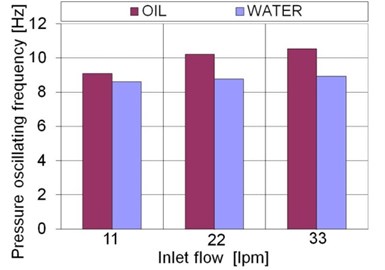
Figure 9(b) shows the influence of the pressure-oscillating frequency for different inlet fluid flows in the oil and water hydraulic cylinders at a system pressure of 160 bar. It is evident that the pressure-oscillating frequency in the oil hydraulics increases with the inlet oil flow. In the water hydraulic system the pressure-oscillating frequency also increases with the increasing inlet flow, but in this case very low, hard to observe. The highest pressure-oscillating frequency in the oil hydraulics was 10.5 Hz, at an inlet flow of 33 lpm, and the lowest was 9 Hz at a flow of 11 lpm. The highest pressure-oscillating frequency in the water hydraulics was 8.9 Hz at 33 lpm, and the lowest was 8.6 Hz at a flow of 11 lpm.
Fig. 9Pressure oscillating frequency for the oil and water hydraulics during the pressure-surge effect on the A port of the proportional 4/3 directional valve in response to an instantaneously closed valve for a loaded hydraulic cylinder (163 kg in horizontal position) for a) different inlet pressures (flow= 33 lpm) and b) different flows (pressure= 160 bar)
(a)
(b)
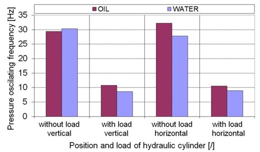
Figure 10 shows the influence on the pressure-oscillating frequency at different positions and for different loads of the water and oil hydraulic cylinders during the pressure-surge effect. The inlet flow was 33 lpm and the system pressure was 160 bar. The lowest pressure-oscillating frequency in the oil hydraulic system, 10.5 Hz, occurred in the case of a loaded oil hydraulic cylinder (with a mass of 163 kg) in the horizontal position. The largest pressure-oscillating frequency in the oil hydraulic system, 32.3 Hz, occurred in the case of an unloaded oil hydraulic cylinder in the horizontal position.
The lowest pressure-oscillating frequency in the water hydraulic system, 8.6 Hz, occurred in the case of a loaded water hydraulic cylinder (with a mass of 163 kg) in the horizontal position. The largest pressure-oscillating frequency in the water hydraulic system, 30.3 Hz, occurred in the case of an unloaded water hydraulic cylinder in the vertical position.
The largest difference in the frequency of the pressure oscillations between the water and oil hydraulics occurred in the horizontal position of the hydraulic cylinder without any load. In this case the frequency of the pressure oscillations in the oil hydraulics was approximately 4.5 Hz higher than in adequate water hydraulics under similar conditions.
Fig. 10Pressure-oscillating frequency for oil and water hydraulics during the pressure-surge effect on the A port of the proportional 4/3 directional valve in response to an instantaneously closed valve for different positions of the cylinder and different loads (flow= 33 lpm, pressure= 160 bar)
The inlet pressure influences on the frequency of pressure oscillations during the pressure-surge effect (Fig. 9(a)). In the oil hydraulics the frequencies increased by 8 % with the increase of the inlet pressure, but in the water hydraulics the frequencies of the pressure oscillation decrease with the increasing inlet pressure.
Knowing, that means calculating in advance, the frequency of pressure oscillations is very important for the correct setting of the time ramp of continuously operating directional spool sliding valves. Correctly tuned time ramp for the proportional control valve should prevent hydraulic machines and devices from the harmful (and potentially destructive) consequences of the hydraulic surge effect. Taking into account recommendation [21] for setting the time-ramp 3 to 4 times longer than the period of the pressure oscillations is a good solution for satisfactory decrease of the pressure-surge effect.
5. Discussion
Carrying out this research work knowledge about following properties concerning pressures in oil and water power-control hydraulic systems and comparisons between both of them was obtained.
The results of the measured pressure increases during the pressure-surge effect differed as expected considering some different properties of oil and water. Pressure increases for the water hydraulic test rig were from 8 to 14 bar higher than the pressure increases for the similar oil hydraulic test rig. The differences in the pressure increases between the water and oil hydraulics mainly depend on the different coefficients of friction in the water and oil hydraulic cylinders and the influence of gravity (vertical working cylinders) in connection with the lower compressibility of water. In the case of the load, a mass of 163 kg in vertical position we obtained the highest difference of 14 bar between the water and oil hydraulics.
The results of the measured pressure oscillating frequency during the pressure-surge effect were similar for the water hydraulic test rig, at most 20 % lower, comparing to those for the adequate oil hydraulic test rig (depending on the type of measurement configuration).
Mathematical model gives higher pressure-oscillation frequency for the water hydraulics than for the oil hydraulics with similar working parameters. Yet most of our measurements show the inverse results. The reason for this difference probably lies in very large internal damping of the water hydraulic cylinder. The high friction of the standard seals inside the water hydraulic cylinder had important influence on the higher internal damping. In fact the internal damping in the water hydraulic cylinder was so high that aperiodical movement (non-oscillating) of the water cylinder rod almost occurred. An increased pressure damping tends to decrease the pressure-oscillating frequency. That follows from mathematical model.
Compressibility in connection with the pressure-surge effect.
Compressibility of the hydraulic fluid is one of the most important parameters having significant influence on transient phenomena in power-control hydraulics. A less compressible fluid, for example water, causes higher pressure increases than the more compressible hydraulic mineral oil. Water has approximately 45 % lower compressibility [2] than the hydraulic mineral oil.
Table 1 shows summary of the dynamic-transient hydraulic parameters for the oil and water hydraulics.
Table 1Summary of differences in the dynamic-transient parameters of the oil and water hydraulics
No. | Dynamic-transient parameter | Test rig | Comment (response of the water hydraulics compared to the oil hydraulics) | |
Oil | Water (in comparison with oil) | |||
1. | Pressure increase during the pressure-surge effect | 100 % | +10 % → +30 % | Higher pressure during the pressure-surge effect – acceptable |
2. | Pressure oscillating frequency during the pressure-surge effect | 100 % | 0 % → –20 % | Slower oscillating – acceptable |
6. Conclusions
Results of the dynamic characteristic measurements and the mathematical model for the oil and water hydraulics show differences and similarities between the two hydraulic systems.
Pressure increases during the pressure-surge effect were on average 20 % higher in the water hydraulics than in the oil hydraulics for the same parameters.
Frequencies of the pressure oscillations during the pressure-surge effect were on average 10 % lower in the water hydraulics than those in the oil hydraulics for the same parameters. Yet it is the consequence of high friction inside the hydraulic cylinder which was used for measurements. We expect inverse results later using cylinder specially developed for water as hydraulic fluid.
These results make us optimistic about the possibility of using water hydraulics and will lead us to conduct future research and to develop water-based power-control hydraulics.
References
-
Bramah J. The hydraulic press. Patent No. 2045, UK, 1795.
-
Trostmann E. Water hydraulics control technology. Technical University of Denmark, Lyngby, 1996.
-
MurrenhoffH. Grundlagen der fluidtechnik teil 1: Hydraulik. 5th ed., IFAS, Aachen, 2007.
-
Kalin M., Majdič F., Vižintin J., Pezdirnik J., Velkavrh I. Analyses of the long-term performance and tribological bechaviour of an axial piston pump using dimond-like-carbon-coated piston shoes and biodegradable oil. Journal of Tribology, Vol. 130, 2008.
-
Kalin M., Majdič F., Vižintin J., Pezdirnik J. Performance of axial piston pump using DLC-coated piston shoes and biodegradable oil. The 12th Nordic Symposium on Tribology, Helsingor, Denmark, 2006, p. 10.
-
Kalin M., Vižintin J. A comparison of the tribological behaviour of steel/steel, steel/DLC and DLC/DLC contact when lubricated with mineral and biodegradable oils. Wear, Vol. 261, Issue 1, 2006, p. 22-31.
-
Barriga J., Kalin M., Van Acker K., Vercammen K., Ortega A., Leiaristi L. Tribological performance of titanium doped and pure DLC coatings combined with a synthetic bio-lubricant. Wear, Vol. 261, 2006, p. 9-14.
-
Kalin M., Vižintin J., Vercammen K., Arnšek A., Barriga J., Van Acker K. Tribological performance of lubricated DLC coatings using biodegradable oils. The coatings in Manufacturing Engineering, 2004, p. 457-465.
-
J. Barriga, M. Kalin, K. Van Acker, K. Vercammen, A. Ortega, L. Leiaristi Tribological characterisation and validation of carbon based coatings combined with bio-lubricants. Proceedings of the 11th Nordic Symposium on Tribology. Norway, p. 508-517.
-
Koskinen K., Leino T., Riipinen H. Sustainable development with water hydraulics – possibilities and challenges. Proceedings of the 7th JFPS Interantional Symposium in Fluid Power, Toyama, Japonska, Vol. 1, 2008, p. 11-18.
-
Šitum Ž. Applying different controller structures for position control of pneumatic servo system. Strojarstvo, Vol. 48, Issue 5-6, 2006, p. 261-271.
-
Šitum Ž., Petrić J. Modeling and control of servopneumatic drive. Strojarstvo, Vol. 43, Issue 1-3, 2001, p. 29-39.
-
Šitum Ž., Pavković D., NovakovićB. Servo pneumatic position control using fuzzy pid gain scheduling. Journal of Dynamic Systems, Measurement and Control – Trans. of the ASME, Vol. 126, 2004, p. 376-387.
-
KitagawaA. Co-operation between universityes and water hydraulic companies in Japan. The Sixth Scandinavian International Conference on Fluid Power, Tampere, Finland, 1999.
-
Majdič F., Pezdirnik J.,Kalin M. Comparative tribological investigations of continuous control valves for water hydraulics. The Tenth Scandinavian International Conference on Fluid Power, Tampere, Finland, 2007.
-
Majdič F., Pezdirnik J. Advances in Water Power-Control Hydraulics Experimental Research. Journal of Mechanical Engineering, Vol. 54, Issue 12, 2008, p. 841-849.
-
Majdic F., Velkavrh I., Kalin M. Improving the performance of a proportional 4/3 water–hydraulic valve by using a diamond-like-carbon coating. Wear, Vol. 297, 2013, p. 1016-1024.
-
Majdič F., Pezdirnik J. Oscillations of cylinder piston rod – comparison amplitudes and frequencies for the transient phenomena in tap water- and oil-based PCHS. Journal of Vibroengineering, Vol. 14, Issue 1, 2012, p. 352-362.
-
Majdič F., Pezdirnik J.,Kalin M. Lifetime test of new water hydraulic proportional directional control valve. The Seventh International Conference on Fluid Power, Aachen, Germany, 2010.
-
Pezdirnik J. Transient phenomena in ironworks hydraulic systems. Master’s degree work, Faculty of Mechanical Engineering, Ljubljana, 1984.
-
D. Kretz, A. Schmitt Mannesmann Rexroth Engineering Proportional- und Servoventil-Technik, Der Hydraulik Trainer, Band 2. Lohr am Main, 1998.
About this article
The authors greatly acknowledge the Slovenian Research Agency ARRS (Proj. No. L2-9407 from 2006) and Tajfun Planina d. o. o. (Planina pri Sevnici, Slovenia) for their financial and technical support. The majority of the components for the oil test rig were donated by Kladivar Žiri d. d. (Žiri, Slovenia), which the authors also greatly appreciate.
