Abstract
Vibration measurement is one of the most widely used indirect methods of tool condition monitring, but vibration signal features may be affected by overhang lenght. In turning process, it is known that for the best overall machining results, tool overhang should be kept to a minimum. However, a longer tool overhang may be required depending on the geometry of the workpiece and in situations such as internal turning process. The long overhang increases vibration. In this paper the relations between tool overhang and the most commonly used signal features is investigated.
1. Introduction
Several kinds of sensors and signal processing techniques have been developed for the direct or indirect detection of tool wear and breakage and the identification of chatter in machining process. Sensors are subjected to analogue and digital signal conditioning and processing with the aim of generating functional signal features correlated with tool state. Sensor signal features are then fed to and evaluated by cognitive decision making support systems for the final diagnosis [1]. Vibration measurement is one of the indirect methods of tool condition monitring [1]. Metal cutting processes can entail three different types of mechanical vibrations that arise due to the lack of dynamic stiffness of one or several elements of the system composed by the machine tool, the tool holder, the cutting tool and the workpiece. These three types of vibrations are known as free vibrations, forced vibrations and self-excited vibrations [2]. The nature of the vibration signal arising from the metal cutting process is such that it incorporates facets of free, forced, periodic and random types of vibration [3]. Several machining variables, such as cutting speed, depth of cut, feed rate, workpiece material, and cutting tool geometry have significant effects on the machining process and vibrations [1, 4]. A large number of research works has been carried out on the influence of these parameters on turning process. Tool overhang is also a machining parameter in turning process which has significant effect on metal cutting. Tool overhang () is defined as the distance that the tool extends from the end of tool holder (Fig. 1). The overhang is a variable that can be used to tune the turning process and infuences on vibration signal features that is used for tool condition monitoring, Any variation in the overhang length during machining process may misleads the decision making process about the tool state. In this paper the relations between tool overhang and vibration signal features is investigated. Although various signal features have been employed in the literatures, we focused on the Peak, Max-min and RMS in the time domain, Powr Spectral Density in the frequency domain and STFT in the time – frequency domain, since they are the most commonly used features.
2. Vibrations in metal cutting
In a machining process, three different types of mechanical vibrations are present due to a lack of dynamic stiffness/rigidity of the machine tool system comprising tool, tool holder, work piece and machine tool itself. These are the free, forced and self-excited vibrations. Free or transient vibrations, are induced by shock, such as impulses transferred to the structure of machine tool or from the initial engagement of cutting tools. Forced vibrations, resulting from periodic forces within the system such as unbalance defects in machine tool components ( like gears, spindles and bearings), and vibration transmitted through the foundations from other machinery in the shop. Self-excited chatter vibrations, usually resulting from a dynamic instability of the cutting process (such as cutting with large tool-work engagements), are still not fully understood due to its complex nature. They are most harmful for any machining process. Free and forced vibrations can be easily identified and sources of vibration can be removed, but chatter vibrations are less easily controlled. It is important to suppress vibrations of the machine tool structure as their presence results in poor surface quality, unacceptable inaccuracy, tool wear and machine tool damage [7-9]. Typically, chatter arises from a lack of stiffness in the tool in the direction of the tool-holder or in a normal direction. Indeed, the most common cases represented in the literature usually involve facing operations where the tool vibrates in the feed direction (called type A chatter by Tobias et al.). However, there is another type of chatter (type B chatter) where the cutting edge vibrates parallel to the cutting speed direction or to a component in this direction. Type A chatter arises for short overhangs, generally in the radial direction, whereas type B chatter occurs for large tool overhangs. Fig. 2 shows chatter due to a tangential mode for longitudinal turning operations [10].
Fig. 1Tool holder deflection due to tangential force [5, 6]
![Tool holder deflection due to tangential force [5, 6]](https://static-01.extrica.com/articles/14705/14705-img1.jpg)
![Tool holder deflection due to tangential force [5, 6]](https://static-01.extrica.com/articles/14705/14705-img2.jpg)
Fig. 2Chatter due to a tangential mode for longitudinal turning operations [10]
![Chatter due to a tangential mode for longitudinal turning operations [10]](https://static-01.extrica.com/articles/14705/14705-img3.jpg)
3. The Effect of tool holder overhang on cutting tool vibration
It is known that for best overall machining results, tool overhang should be kept to a minimum, however a longer tool overhang may be required depending on the geometry of the workpiece and in situations such as internal turning process. The long overhang increases vibration. Increasing the vibration of cutting tool through increasing the tool overhang will cause the increase in irregularity of surface texture of work piece and decrease in tool life and productivity of turning process. The surface roughness of work piece is proportional to cutting tool acceleration [11]. Abouelatta and Madi in their research developed a mathematical model for surface roughness prediction based on cutting parameters and tool vibration. They used tool overhangs as input variable and selected 38 and 70 mm tool overhangs [12]. Kassab and Khoshnaw in their study to find correlation between surface roughness and cutting tool vibration in turning process conducted some cutting test on the lathe machine and examined the ranges of process cutting parameters (cutting speed, depth of cut, and feed rate) and tool overhanging. They selected 25, 30, 35 and 40 mm overhangs. Their results show that surface roughness increased with an increase in tool vibration [11]. The cutting tool can be considered as a cantilever beam (Fig. 1). In cantilever beams deflection which is calculated by the Eq. 1 is a function of length of overhang:
Here, is the cutting force, is the tool overhang, is the modulus of elasticity, and is the moment of inertia.
It can be seen that deflection is a function of length of overhang in cantilever beams, so a small change in overhang length can greatly change deflection and vibration tendencies. The tool holder is also subjected to the effect of the bending momentum and torque. Since the cutting force is not applied in the symmetry axis, Eq. 1 cannot exactly represent the actual deflection. To determine the displacement of the tool tip more accurately, Kiyak et al. used Castigliano’s Theorem such that the effects of bending momentum and torque are taken into consideration. Although the static coefficient can be easily derived from the formula for a cantilevered beam in Strength of materials, the dynamic factor is the real key to constructing precise stability charts. In chatter due to a tangential mode of a tool, the stability of the system is strongly determined by this coefficient, which differs notably from its static value [10]. For this reason Urbikain et al. proposed a non-dimensional parameter () not only on the dynamic features of the system, but also on the cutting geometry of the tool and will have a decisive influence on the chip thickness. Indeed, this parameter is built from the modal stiffness () and the natural frequency () of the system, the cutting coefficient (), the cutting edge engaged during machining () and the vibration frequency ():
Although evaluation of cutting tool deflections due to increase in tool overhang is important but it is also necessary to investigate how the increase in tool overhang affect the vibration and stability of cutting.
4. Experimental setup and procedure
For the current study, the cutting tests were carried out on a TN50D lathe machine under dry cutting conditions. Figure 3 shows the experimental set-up. A digital microscope was attached to the carriage of the lathe by means of a specially prepared stand to observe foot print of cutting vibration on surface of workpiece. Experiments with different overhang were conducted on the lathe machine and an accelerometer was attached to the shank of cutting tool for measuring vibrations in tangential direction. The experimental instruments and cutting conditions are shown in Table 1.
5. The Effect of tool overhang on vibration signal features of cutting tool
There are several signal features that have been extracted from signals for tool condition monitoring. The most common features are the statistical features in the time domain, amplitude of dominant spectral peaks, signal power in specific frequency ranges, energy in frequency bands, statistic features of band power spectrum such as mean frequency, variance, frequency of the spectrum highest peak , Short Time Fourier Transform (STFT) and wavelet transform [1, 13]. For example Fig. 4 shows the Power Spectral Density (PSD) diagram of the vibration signals in feed direction with respect to tool wear in turning process and Fig. 5 shows the peak of displacement and acceleration of cutting tool with respect to tool wear in milling process.
Fig. 3Experimetal set up
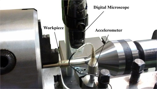
Table 1The experimental instruments and cutting conditions
TN50B | Lathe Machine |
Brass bars of diameter 30 mm | Workpiece |
Coated Carbide | Insert |
Global Test AP98 | Accelerometer |
Advantech 4704 | Data Acquisition System |
Insize | Digital microscope |
MarSurf M 300 C | Roughness meter |
Depth of Cut = 1 mm | Machining Conditions |
Spindle Speed = 1000 rev/min | |
Feed rate = 0.20 mm/rev | |
40, 50, 60, 70, 80, 90, 100, 110 | Overhang Length (mm) |
Fig. 4The PSD diagram of the vibration signal in feed direction [14]
![The PSD diagram of the vibration signal in feed direction [14]](https://static-01.extrica.com/articles/14705/14705-img5.jpg)
In this research the anaysis of time-domain waveform of acceleration signal, which shows how the amplitude of the signal changes over time in tangential direction is performed by several vibration level measurements. Peak, Max-Min and RMS of acceleration signal for diffrent tool overhang lengths are compared. The RMS level of a signal is the square root of the mean value of the squared signal:
where is the integration time or measurement time. Fig. 6 shows the effect of tool overhang on vibration level measurements. The figure indicates that the Peak, Max-Min and RMS level of acceleration signal increases with the increase of tool overhang.
Fig. 5Relationship between the vibration amplitude and the tool wear: (a) displacement, (b) acceleration [15]
![Relationship between the vibration amplitude and the tool wear: (a) displacement, (b) acceleration [15]](https://static-01.extrica.com/articles/14705/14705-img6.jpg)
![Relationship between the vibration amplitude and the tool wear: (a) displacement, (b) acceleration [15]](https://static-01.extrica.com/articles/14705/14705-img7.jpg)
Fig. 6The effect of tool overhang on vibration level measurements
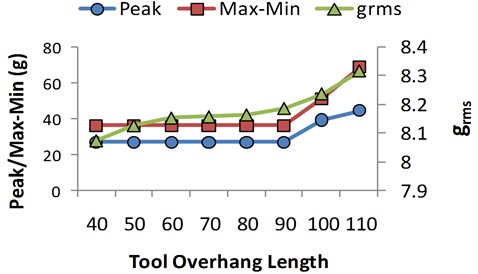
Fig. 7Power spectral density function for diffrent tool overhangs
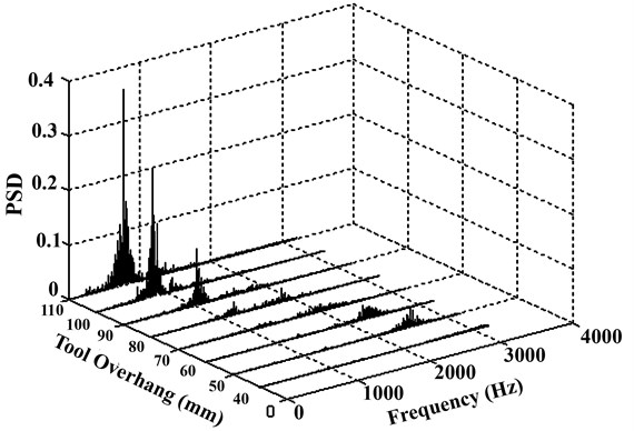
Frequency domain analysis of vibration is performed using PSD function. The maximum value of PSD is a reliable indicator of the overal stability of the machining process [16]. PSD describes how the power of a signal or time series is distributed over the different frequencies. In Fig. 7 the waterfall graph displays the power spectral density function of accelertion signal for diffrent tool overhangs
Fig. 8 which is derived from Fig. 7, indicates that the maximum of power spectral density () in the tangential direction increases with the increase of tool overhang and frequency at maximum of power spectrum density () decreases.
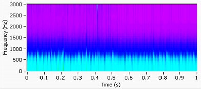
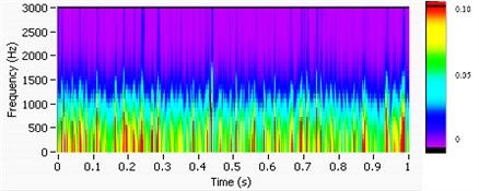
Fig. 9 shows the STFT of the signals related to different overhang lengths, STFT uses a window sliding along the time axis to characterize the change of frequency components at different time intervals.
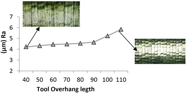
Fig. 10 shows the effect of tool overhangs on surface roughness and texture of workpiece. It is observed that increasing the vibration of cutting tool through increasing the tool overhang will cause the increase in roghness and irregularity of surface of work piece.
Fig. 8Effect of overhang on maximum of PSD (PSDmax) and frequency at maximum of PSD (FreqPSD)
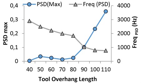
Fig. 9STFT of the signals related to different overhangs: (a) L= 40mm (b) b= 110 mm
a)
b)
Fig. 10The effect of vibration resulting from increasing tool overhangs on surface roughness and texture of workpiece
6. Conclusions
In this study, the relations between tool overhang and vibration signal features are investigated. Although various signal features have been employed in the literatures, we focused on the Peak, Max-Min and RMS in the time domain, Powr Spectral Density in the frequency domain and STFT in the time – frequency domain, since they are the most commonly used features. The resaults show that Peak, Max-Min and RMS level of vibration signal increase with increased tool overhang. The resaults also indicate that the maximum of power spectral density in the tangential direction increases with the increase of tool overhang but the frequency at maximum of power spectrum density decreases. The resaults are similar to tool wear, therefore varying the overhang length during machining process may misleads the decision making process of monitoring system about the tool state. Based on this study, it can be concluded that vibration signal features in tangential direction are highly affected by overhang length. The surface image of workpiece clearly shows the effect of vibrations resulting from increasing of the tool overhang.
References
-
Teti R., Jemielniak K., Donnell G. O, Dornfeld D. Advanced monitoring of machining operations. CIRP Annals – Manufacturing Technology, Vol. 59, 2010, p. 717-739.
-
S. A. Tobias Machine Tools Vibrations (Vibraciones en Ma ´quinas-Herra- mientas). URMO, Spain, 1961.
-
Dimla E. Dimla Snr. Sensor signals for tool-wear monitoring in metal cutting operations – a review of methods. International Journal of Machine Tools & Manufacture, Vol. 40, 2006, p. 1073-1098.
-
G. Litak, R. Rusinek Vibrations in stainless steel turning: multifractal and wavelet approaches. Journal of Vibroengineering, Vol. 13, Issue 1, 2011, p. 102-108.
-
Kiyak M., Kaner B., Sahin I., Aldemir B., Cakir O. The dependence of tool overhang on surface quality and tool wear in the turning process. Int. J. Adv. Manuf. Techno., Vol. 51, 2010, p. 431-438.
-
Sandvic Switch to hard-part turning, http://www2.coromant.sandvik.com/coromant/pdf/Switch toHard_part_ turning/C-1040-069.pdf
-
Siddhpura M., Paurobally R. A review of chatter vibration in turning. International Journal of Machine Tool & Manufacture, Vol. 51, 2012, p. 27-47.
-
Quintana G., Ciurana J. Chatter in machining processes: A review. International Journal of Machine Tools & Manufacture, Vol. 51, 2011, p. 363-376.
-
Boothroyd G., Knight W. A. Fundamentals of Machining and Machine, 2006.
-
Urbikain G., Fernandez A., Lopez de Lacalle L. N., Gutierrez M. E. Stability lobes for general turning operationswith slender tools in the tangential direction. International Journal of Machine Tools & Manufacture, Vol. 67, 2013, p. 35-44.
-
Kassab S. Y., Khoshnaw Y. K. The effect of cutting tool vibration on surface roughness of workpiece in dry turning operation. Eng. Tech., Vol. 25, Issue 7, 2007, p. 879-889.
-
Abouelatta O. B., Madi J. Surface roughness prediction based on cutting parameters and tool vibrations in turning operations. J. Mater. Process. Technol., Vol. 118, 2001, p. 269-277.
-
Zhu Kunpeng, Wong Yoke San, Hong Geok Soon Wavelet analysis of sensor signals for tool condition monitoring A review and some new results. International Journal of Machine Tools & Manufacture, Vol. 49, 2009, p 537-553.
-
Jiang C. Y., Zhang Y. Z., H. J. Xu In-process monitoring of tool wear stage by the frequency band-energy method. Annals of the CIRP, Vol. 36, Issue 1, 1987, p. 45-48.
-
Sadettin Orhan S., Ali Osman Er, Necip Camus-cu, Ersan Aslan Tool wear evaluation by vibration analysis during end milling of AISI D3 cold work tool steel with 35 HRC hardness. NDT&E International, Vol. 40, 2007, p. 121-126.
-
Tsai S. Y., Eman K. F., Wu S. M. Chatter suppression in turning. NAMRC proceedings, 1980, p. 389-402.
