Abstract
Beginning with incomplete mode shape measurement data, this study presents analytical equations to predict the actual stiffness and mass matrices. The measured modal data, including the measurement, manufacturing and modeling errors, should be updated for subsequent analysis. In this study, the incomplete mode shape data are expanded to a full set of degrees-of-freedom (DOFs) based on the generalized inverse method and the concept of residual force vector. The corrected parameter matrices are straightforwardly derived using the estimated mode shape data and the pseudo inverse method. The validity of the proposed method is evaluated based on the number of measured modes in an application, and its limitations are investigated.
1. Introduction
Modal data provide extremely useful information that can assist in the design of virtually any structure. The visualization of mode shapes is included in the design process, and the development of a modal model is useful for simulation and design studies. Measured and analytical data differ because of measurement noise and model inadequacies. It is desirable to correct the parameter matrices to provide satisfactory measurement data for subsequent analysis.
The parameter matrices can be corrected using the measured frequency response function (FRF) or mode shape data. The FRF-based parameter matrix update methods can utilize available measurement data in a certain frequency range and estimate the damping matrix [1-4].
The number of transducers for measurement is less than the number of DOFs in a finite element model, requiring the expansion of measured mode shapes. It is expected that a gap exists in the eigenvalues before and after updating and it should be reduced. There have been numerous attempts to expand the measured data [5-9]. The expansion of mode shape data requires the modification of the eigenvalue function. The residual force method is one modification method. The residual force is obtained by substituting the experimentally measured modal frequencies and mode shape, along with the analytical mass and stiffness matrices from the analytical model structure, into the eigenvalue function. Yang and Liu [10] presented a mode shape expansion method based on the best achievable eigenvector concept to solve the incomplete measurement problem. Zhao and Zhang [11], Yun et al. [12] and Gafka and Zimmerman [13] introduced a mode shape expansion method to estimate motion at all DOFs. Friswell and Mottershead [14] provided a comprehensive overview that illustrates many of the different techniques and factors involved in updating a finite element model. Many researchers have presented analytical methods to correct both analytical and actual stiffness matrices to satisfy the dynamic equation and the orthogonality constraints [15-27].
This work presents analytical methods to expand incomplete measurement data to a full set of DOFs using the generalized inverse method provided by Eun [28] and the residual force vector. Using the estimated modal data set, the residual force vector, fundamental linear algebra and the Moore-Penrose inverse, the variation in parameter matrices is predicted. The validity of the proposed method is evaluated based on the number of measured modes in an application, and its limitations are investigated.
2. Expansion of incomplete mode shape data
Considering modeling and measurement errors, the parameters of the finite element model should be corrected for proper subsequent analysis. However, it is not practical to measure the responses at a full set of DOFs of the system. The incomplete measurement data should be expanded, and the estimated full data utilized in predicting the parameter matrices. The mode shape expansion to satisfy the measured mode shape data is derived from the modification of the eigenvalue function.
The dynamic behavior of a structure, which is assumed linear and approximately discretized for n DOFs without damping and external excitations, can be described by the following equation of motion:
where Ma and Ka denote the n×n analytical mass and stiffness matrices, respectively.
Assuming that the analytical parameter matrices Ma and Ka are exact in modeling, they should be corrected to eliminate the inconsistency between the analytical and experimental results. The expansion of incomplete data is derived using the generalized inverse method.
By substituting u=φaejΩt, where j=√-1 and φa is the analytical mode shape vector, into Eq. (1), the eigenvalue equation for the undamped system is derived as follows:
Assume that the first r (r<n) modal frequencies and the corresponding mode shape vectors at s (s<n) measurement positions are provided for data expansion and parameter identification. The actual mode shape vector φx is composed of unmeasured and measured sets. Assuming that the first r mode shape sets at s different locations are measured, the constraints at each mode are expressed by the s measured mode shape data as follows:
where Ai is a s×n Boolean matrix defining the measurement locations at the ith mode and bi is the corresponding s×1 measurement data vector.
The updated mode shape φi,x is expanded to a full data set to satisfy the constraint equation of Eq. (3). The coefficient matrix (Ka-Ω2iMa) in Eq. (2) is a rank-deficiency matrix. By inserting the frequencies Ωi,x (i=1,2,…,r), r<n and corresponding mode shape vector φi,x into Eqn. (2), it is modified as the eigenvalue function of the full rank coefficient matrix. The matrix is expressed by the summation of the analytical mode shape φi and the variation in the mode shape ∆φi as follows:
where φi represents the mode shape vector obtained from the analytical eigenvalue equation of Eq. (2), and Δφi denotes the variation in mode shapes to be updated with the actual measurements. Based on the generalized inverse method, the variation in the mode shape can be derived.
The variation in mode shape is derived using the measured mode shape data based on the generalized inverse method. The variation is expressed as:
where Ri=Ka-Ω2i,xMa.
Substituting Eq. (5) into Eq. (4), the ith estimated mode shapes for a full set of DOFs are simply obtained. The estimated mode shape data are utilized to identify the parameter matrices.
3. Prediction of parameter matrices
We derive the mathematical forms of the corrected stiffness and mass matrices based on the estimated mode shapes. Based on the expanded mode shapes and the measured frequencies, the eigenvalue equation for the undamped system is expressed as:
where Ωi,x and φi,x denote the ith measured frequency and corresponding expanded mode shape vector. Expressing the actual parameter matrices M and K by M=Ma+ΔM and K=Ka+ΔK and inserting them into Eq. (6), results in the following:
where Ri=-(Ka-Ω2i,xMa)φi,x, and ∆M and ∆K are the variation in the mass and stiffness matrices, respectively. Expanding Eq. (7) to the first s modes results in the following:
Solving Eq. (8) with respect to the parameter variation matrices results in the following:
Consequently, the variations in parameter matrices can be simply and explicitly obtained under the assumption that the mode shapes are exact. Eq. (9) exhibits that the exactness of the parameter matrices depends on the precision of estimated mode shape data. In the following application, the validity of the proposed method is investigated, and its limitations are examined.
4. Application
The derived mode shape expansion and correction approaches are considered in a plane truss structure in Fig. 1. The nodal points and the members are numbered in the figure. Each corresponding pair of nodal displacement components (ui,vi) is expressed by a set of forces (Hi,Vi). The structure has nine DOFs, except for the boundary conditions: [u2v2u3v3u4v4u5v5u6]T. Each member has an elastic modulus of 200 GPa, a cross-sectional area of 2.5×10⁻³m2 and unit mass per unit volume of 7.860kg/m3.
For this numerical experiment, the actual stiffnesses of the truss structure are assumed as follows:
where k'i denotes the ith analytical stiffness. The stiffness varies from 1.5 % to 37.5 % of the theoretical stiffness. The mass is assumed as invariant.
The measurement was performed at five different DOFs corresponding to [v2v3u4u5v5]T. This numerical example considered the following three different measurement cases with varying natural frequencies and corresponding mode shape data: a) Case 1: only the first natural frequency and mode, b) Case 2: the first two natural frequencies and corresponding modes, and c) Case 3: the first three natural frequencies and corresponding modes. Using and expanding the measured natural frequencies and corresponding mode shape data for each case, the stiffness and mass matrices were estimated utilizing Eq. (9). Using the predicted parameter matrices, the eigenvalues were reevaluated and compared as shown in Table 1. The eigenvalues measured in each case were identical with those predicted using the estimated parameter matrices. The eigenvalue estimates were as follows:
a) Case 1: eigenvalue of 0.0680×10⁶(rad./sec.)2;
b) Case 2: eigenvalues of 0.0680×10⁶(rad./sec.)2 and 0.2633×10⁶(rad./sec.)2;
c) Case 3: eigenvalues of 0.0680×10⁶(rad./sec.)2, 0.2633×10⁶(rad./sec.)2 and
0.6189×10⁶(rad./sec.)2.
However, the other eigenvalues, except for the measured modes, were not consistent with the actual values. This indicates that accurate parameter matrices cannot be obtained from incomplete measurements.
Fig. 1A planar truss structure
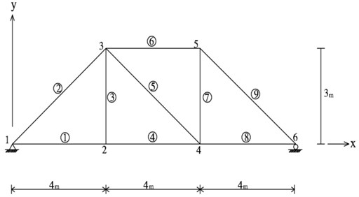
Table 1Eigenvalues obtained analytically and experimentally (unit: ×106(rad./sec.)2)
Mode number | 1st | 2nd | 3rd | 4th | 5th |
Before updating | 0.0634 | 0.2422 | 0.5851 | 1.7548 | 2.8366 |
Actual truss | 0.0680 | 0.2633 | 0.6189 | 1.9585 | 2.9804 |
Numerical results considering only the first mode | 0.0680 | 0.2422 | 0.5851 | 1.7582 | 2.8315 |
Numerical results considering the first two modes | 0.0680 | 0.2633 | 0.5870 | 1.7598 | 2.8200 |
Numerical results considering the first three modes | 0.0680 | 0.2633 | 0.6189 | 1.7617 | 2.8158 |
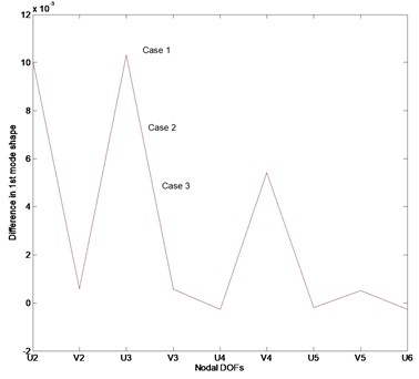
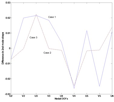
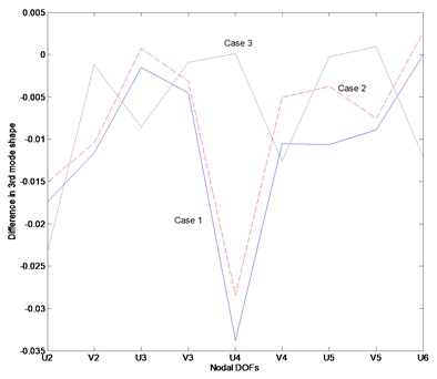
Fig. 2 represents the difference between the estimated mode shapes and the actual mode shapes for each case. The mode shape data in this work were transformed as normalized data. The first mode shape for each case is estimated with a small margin of error as depicted in Fig. 2(a). However, the second and third modes exhibit greater inconsistencies than the first mode. It is recognized that this inconsistency is a result of the incomplete mode shape measurement data and the inaccurate prediction of parameter matrices.
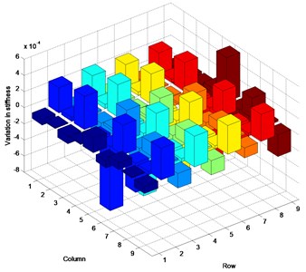
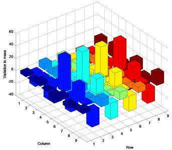
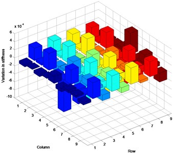
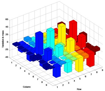
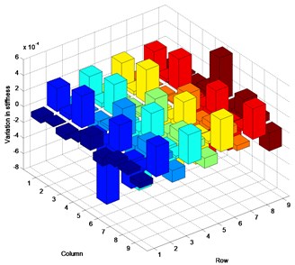
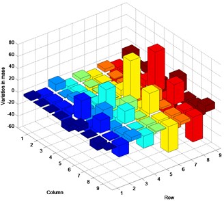
Fig. 3 represents the inconsistency in the satisfaction of actual parameter matrices in the three cases. This numerical example was designed to estimate the stiffness matrix as established the above. However, the plots indicate that the mode shape calculations produced greater change in the mass matrix than in the stiffness matrix. A small change in the stiffness matrix is observed, contrary to expectations. The change of the analytical stiffness matrix is demonstrated by the variation in the mass matrix, yielding the prescribed eigenvalues and corresponding mode shapes. In all cases, the numerical values in the predicted parameter matrices are estimated with a similar margin of error.
Fig. 2Difference between the estimated and actual normalized mode shape: a) Case 1, b) Case 2, c) Case 3
a)
b)
c)
This application demonstrates that it is not easy to accurately estimate the mode shape and the parameter matrices if insufficient measurement data are provided. Although the natural frequencies and corresponding mode shapes are obtained by the proposed method, the change in the analytical stiffness matrix is mostly lost in the variation of the mass matrix.
From the application, it is understood that it’s not easy to accurately estimate the mode shape as well as the parameter matrices if the insufficient measurement data are given. Although the natural frequencies and corresponding mode shapes are obtained by the proposed method, the change of the analytical stiffness matrix is mostly pervaded into the variation of the mass matrix.
5. Conclusions
In this study, the expansion of incomplete mode shape measurement data and the estimation of the parameter matrices were derived. The first mode shape is estimated with a small margin of error regardless of the number of measured mode shapes. The second and third modes exhibit greater inconsistencies than the first mode. The method does not provide the accurate mode shapes for a full set of DOFs and parameter matrices because of the incomplete measurement of mode shapes. The change of the analytical stiffness matrix is mostly lost in the variation of the mass matrix by the proposed method.
Fig. 3Inconsistency between estimated and actual parameter matrices: a) stiffness variation in Case 1, b) mass variation in Case 1, c) stiffness variation in Case 2, d) mass variation in Case 2, e) stiffness variation in Case 3, f) mass variation in Case 3
a)
b)
c)
d)
e)
f)
References
-
Mottershead J. E., Stanway R. Identification of structural vibration parameters by using a frequency domain filter. Journal of Sound and Vibration, Vol. 109, Issue 3, 1986, p. 495-506.
-
Friswell M. I., Penny J. E. T. Updating model parameters from frequency domain data via reduced order models. Mechanical Systems and Signal Processing, Vol. 4, Issue 5, 1990, p. 377-391.
-
Lee U., Shin J. A frequency response function-based structural damage identification method. Computers and Structures, Vol. 80, Issue 2, 2002, p. 117-132.
-
Rahmatalla S., Eun H. C., Lee E. T. Damage detection from the variation of parameter matrices estimated by incomplete FRF data. Smart Structures and Systems, Vol. 9, 2012, p. 55-70.
-
O’Callahan J. A procedure for an improved reduced system (IRS) model. Proceedings of the 7th IMAC, Las Vegas, Nevada, USA, 1989, p. 17-21.
-
Kenneth F. A., Francois H. Dynamic mode shape expansion using mass orthogonality constraints. Proceedings of the 18th IMAC, Texas, USA, 2000, p. 1496-1502.
-
Ewins D. J. Adjustment or updating of models. Sādhanā, Vol. 25, 2000, p. 235-245.
-
Avitabile P., O’Callahan J. Dynamic expansion of FRFs for the full FRF matrix. Proceedings of the 19th IMAC, Orlando, Florida, USA, 2001.
-
Avitabile P., O’Callahan J. Frequency response function expansion for unmeasured translation and rotation dofs for impedance modeling applications. Mechanical Systems and Signal Processing, Vol. 17, Issue 4, 2003, p. 723-745.
-
Yang Q. W., Liu J. K. Structural damage identification based on residual force vector. Journal of Sound and Vibration, Vol. 305, Issue 1-2, 2007, p. 298-307.
-
Zhao J., Zhang L. A method for structural damage identification using residual force vector and mode shape expansion. International Conference on Multimedia Technology, Hangzhou, China, 2011, p. 945-949.
-
Yun G. J., Ogorzalek K. A., Dyke S. J., Song W. A parameter subset selection method using residual force vector for detecting multiple damage locations. Structural Control Health Monitoring, Vol. 17, Issue 1, 2010, p. 48-67.
-
Gafka G. K., Zimmerman D. C. Structural damage detection via least squares dynamic residual force minimization with quadratic measurement error inequality constraint. Proceedings of the 14th International Modal Analysis Conference, 1996, p. 1278-1284.
-
Friswell M. I., Mottershead J. E. Finite element model updating in structural dynamics. Solid Mechanics and its Applications, Kluwer Academic Publishers Group, 1995, p. 1-286.
-
Baruch M., Bar-Itzhack I. Y. Optimal weighted orthogonalization of measured modes. AIAA Journal, Vol. 17, Issue 8, 1979, p. 927-928.
-
Baruch M. Optimal correction of mass and stiffness matrices using measured modes. AIAA Journal, Vol. 20, Issue 11, 1982, p. 1623-1626.
-
Berman A. Mass matrix correction using an incomplete set of measured modes. AIAA Journal, Vol. 17, Issue 10, 1979, p. 1147-1148.
-
Berman A., Nagy E. J. Improvement of a large analytical model using test data. AIAA Journal, Vol. 21, Issue 8, 1983, p. 1168-1173.
-
Kabe A. M. Stiffness matrix adjustment using mode data. AIAA Journal, Vol. 23, Issue 9, 1985, p. 1431-1436.
-
Caeser B., Pete J. Direct update of dynamic mathematical models from modal test data. AIAA Journal, Vol. 25, Issue 11, 1987, p. 1494-1499.
-
Zimmerman D. C., Widengren M. Correcting finite element models using a symmetric eigenstructure assignment technique. AIAA Journal, Vol. 28, Issue 9, 1990, p. 1670-1676.
-
Wei F. S. Stiffness matrix correction from incomplete test data. AIAA Journal, Vol. 18, Issue 10, 1980, p. 1274-1275.
-
Wei F. S. Analytical dynamic model improvement using vibration test data. AIAA Journal, Vol. 28, Issue 1, 1990, p. 175-177.
-
Wei F. S. Mass and stiffness interaction effects in analytical model modification. AIAA Journal, Vol. 28, Issue 9, 1990, p. 1686-1688.
-
Lee E. T., Eun H. C. Update of corrected stiffness and mass matrices based on measured dynamic modal data. Applied Mathematical Modelling, Vol. 33, Issue 5, 2009, p. 2274-2281.
-
Lee E. T., Eun H. C. Correction of stiffness and mass matrices utilizing simulated measured modal data. Applied Mathematical Modelling, Vol. 33, Issue 6, 2009, p. 2723-2729.
-
Lee E. T., Rahmatalla S., Eun H. C. Estimation of parameter matrices based on measured data. Applied Mathematical Modelling, Vol. 35, Issue 10, 2011, p. 4816-4823.
-
Eun H. C., Lee E. T., Chung H. S. On the static analysis of constrained structural systems. Canadian Journal of Civil Engineering, Vol. 31, Issue 6, 2004, p. 1119-1122.
About this article
This work was supported by the National Research Foundation of Korea (NRF) Grant funded by the Korea Government (MEST) (No. 2011-0012164).
