Abstract
In order to study the vibration behavior of rotating manipulator in the process of scramming, an experimental test is conducted on the vibration behavior during the process on different initial and measuring conditions. Through the experimental test, the vibration behavior exists two impact phenomena, which are found in the scramming process, and the feature extraction of the two impact phenomena is investigated. The dynamics parameters of the rotating manipulator are identified and hammer experiment is done to verify the dynamics parameters. With these parameters, an envelope model of the second impact response is established, and the applicability of the model is validated by experiments. The method of pasting damping layer on the surface of manipulator is employed to inhibit the vibration which is caused by the first impact. Via the experimental verification, the damping layer takes a certain effect on the vibration elimination.
1. Introduction
Manipulator is one of the most important and commonly used facilities in a variety of engineering applications. For example, the United States Robonaut, Ranger space manipulators can perform complex repair and assembly work on faulty satellites [1-2]. Because of the specificity of the space environment, vibration problem of space manipulator causes the task not being completed, and brings a great loss [3]. Therefore, the vibration behavior of manipulator has a very important effect on the manipulator’s work. Suppressing the vibration has been one of the significant problems to be solved urgently in the engineering field.
A huge amount of research efforts have been devoted to the vibration elimination of manipulator in the literature. Dickerson [4] and Alberts [5] use the passive vibration control method of pasting elasticity damping materials to inhibit the manipulator structural vibration. Book [8] adopts pole assignment technique to design the state feedback controller in order to reduce the vibration of the flexible robot response. Sakawa [6] uses the linear quadratic optimal control theory to define the state feedback gain, and suppress elastic deformation and vibration of flexible robot. Bailey [7] and Plump J. M. [8] completes groundbreaking experiments that organically combine passive vibration control and active vibration control with using piezoelectric materials.
There is not any work on the vibration behavior of manipulator during the rotating and scramming process. This paper presents an experimental study on the vibration behavior of rotating manipulator, and the manipulator’s vibration is restrained by pasting a damping layer. Through the experimental test, repeated impact phenomenon is found in the scramming process of manipulator. Via the feature extraction of repeated impact, the dynamics parameters of rotating manipulator are identified and an envelope model of the second impact response is established.
2. Experimental details and results
An aluminum tube with the length of 73 mm, the width of 25 mm, the height of 500 mm and the wall thickness of 1 mm is fixed on a rotating module, which acts as a rotating manipulator (Fig. 1). The measuring points and the direction of the manipulator’s rotation are shown in Fig. 1.
Fig. 1The manipulator
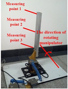
Three acceleration sensors are attached to the three points of the manipulator respectively. The manipulator is controlled under the rotational speed of five working conditions shown in Table 1. Under the five working conditions, the vibration behaviors of the three measuring points are tested.
Table 1The rotational speed of five working conditions
Conditions | 1 | 2 | 3 | 4 | 5 |
Rotational speed (rad/s) | 1.57 | 0.785 | 0.523 | 0.392 | 0.314 |
According to the experimental test, the vibration behavior exists repeated impact phenomena. Repeated impact phenomenon is found in the scramming process of the manipulator (Fig. 2), including the first impact and the second impact.
Fig. 2The vibration behavior of the manipulator
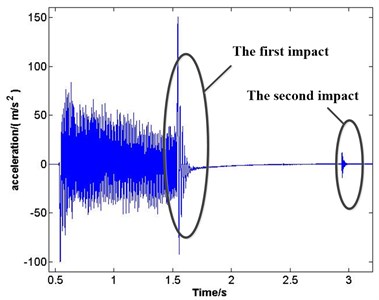
Fig. 2 is obtained from the vibration signal acquisition. The phenomenon of emerging repeated impact happens in the process of manipulator scramming, and the responses of repeated impact are free vibration.
3. The principle of envelope method for free vibration attenuation to identify dynamics parameters
Envelope method for free vibration attenuation is a commonly used method of measuring dynamics parameters [8]. Following the case of single degree of freedom, the principle of envelope method for free vibration attenuation to identify dynamics parameters is explained.
Attenuation response for a damping system of single degree of degree can be expressed as:
where C is amplitude, ωn is natural frequency, t is time of free vibration, φ is phase difference angle and ς is damping ratio of the system. According to Eq. (1), envelope curve equation for displacement attenuation of single-degree-of-freedom vibration is Eq. (2):
Eq. (1) is displacement response, because of different types of vibration picking sensors, time-domain signal of attenuation response of velocity or acceleration may be obtained. Equations of velocity and acceleration are shown as Eq. (3) and Eq. (4):
where B and A are amplitudes of velocity and acceleration attenuation response respectively. And θ and β are the phase difference angles of velocity and acceleration attenuation response respectively. Eq. (4) and Eq. (1) have the same type, so acceleration response curve of single-degree-of-freedom vibration have the same envelope curve with displacement response, and the response curve is shown in Fig. 3.
Fig. 3Time domain response curve of single degree freedom system
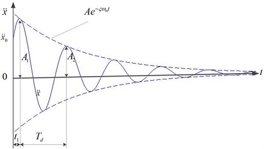
In Fig. 3, damping makes the amplitude of system vibration decrease by geometric attenuation. The ratio of two adjacent amplitude is shown in Eq. (5):
where A1, A2 are the values of two adjacent amplitude, t1 is the time of the first amplitude, η is called damping coefficient [9] and Td is vibration period:
Based on Eq. (6), amplitude reduces to the initial value 1/eςωnTd multiple every vibration period. In fact, in order to avoid inconvenience of taking the index value. Common logarithm damping δ replaces damping coefficient η shown in Eq. (7):
According to Eq. (6) and Eq. (7), equations of damping ratios and natural frequency is shown as follows:
4. Experimental analysis
4.1. Dynamic parameters recognition of the manipulator
Due to the influence of noise, de-noising method [11] is used to the first impact response of measuring point 1 on condition 1. The first impact response after de-noising processing is shown in Fig. 4, and x-axis represents time and y-axis represents acceleration value.
Fig. 4The first impact after de-noising processing
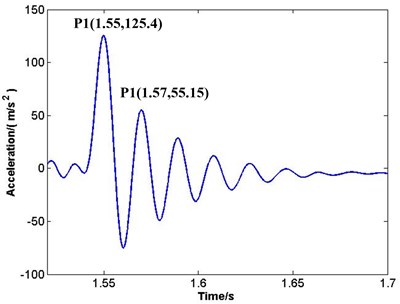
P1, P2 in vibration waveform (Fig. 4) are the first and the second peak points, and coordinate values of the two peaks are P1(1.55, 125.4), P2(1.57, 55.15). That means A1=125.4m/s2 and A2=55.15m/s2. Under other conditions, A1 and A2 can be obtained by the same analysis (Table 2).
Table 2Peak points’ value of A1 and A2 (m/s2)
Measuring point 1 | Measuring point 2 | Measuring point 3 | ||||
A1 | A2 | A1 | A2 | A1 | A2 | |
Condition 1 | 125.4 | 55.15 | 72.46 | 30.53 | 26.15 | 9.11 |
Condition 2 | 45.19 | 18.74 | 26.37 | 9.35 | 8.92 | 2.44 |
Condition 3 | 17.34 | 8.39 | 11.24 | 4.18 | 5.17 | 1.17 |
Condition 4 | 14.64 | 4.73 | 8.76 | 2.57 | 0.74 | 0.2 |
Condition 5 | 14.77 | 5.50 | 8.52 | 2.98 | 3.04 | 0.97 |
According to the data of Table 2, Eqs. (7)-(9), damping ratios (Table 2) and natural frequencies (Table 3) can be obtained in different measuring points of different conditions.
Table 3Damping ratios
Measuring point 1 | Measuring point 2 | Measuring point 3 | |
Condition 1 | 0.131 | 0.149 | 0.164 |
Condition 2 | 0.156 | 0.163 | 0.203 |
Condition 3 | 0.174 | 0.182 | 0.223 |
Condition 4 | 0.181 | 0.192 | 0.228 |
Condition 5 | 0.162 | 0.169 | 0.183 |
Table 4Natural frequencies (Hz)
Measuring point 1 | Measuring point 2 | Measuring point 3 | |
Condition 1 | 52.82 | 50.56 | 50.68 |
Condition 2 | 50.62 | 50.68 | 51.06 |
Condition 3 | 50.77 | 50.85 | 48.85 |
Condition 4 | 50.84 | 50.95 | 51.35 |
Condition 5 | 48.26 | 53.39 | 53.53 |
The average of damping ratios in Table 3 and natural frequencies in Table 4 are 0.177 and 50.86 Hz respectively. Therefore, ς=0.177 and ωn=50.86Hz can evaluate the damping ratio and the natural frequency.
4.2. Hammer experiment
Using hammer experiment [12] verifies the natural frequency (Fig. 5).
Fig. 5Hammer experiment
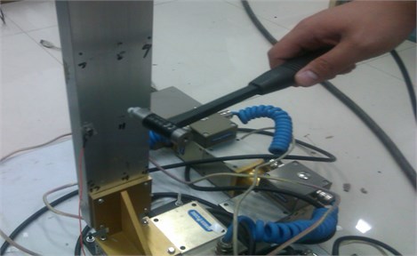
Natural frequencies got from hammer experiment are shown in Table 5.
Table 5Natural frequencies obtained by hammer experiment (Hz)
First-order | Second-order | Third-order | Fourth-order | Fifth-order | |
Natural frequencies | 52.61 | 308.41 | 350.40 | 429.31 | 609.18 |
According to Table 5, first-order natural frequency got from hammer experiment is 52.61 Hz, which is very close to the natural frequency 50.86 Hz got from the first impact of the manipulator (the error is 3.33 %), and proves the value of natural frequency 50.86 Hz is correct.
4.3. Establishing an envelope model of the second impact response
According to these dynamics parameters got from the first impact, an envelope model of the second impact response is established as follows:
where x is the acceleration of vibration, A is the initial acceleration value of the second impact; t is multivariate time and t0 is the initial time. Besides, ς is 0.177 and ωn is 50.86 Hz.
The envelope model is verified by experiment. Fig. 6(a)-(e) respectively represent the second impact response of condition 1 to condition 5.
Fig. 6The second impact and the envelope model
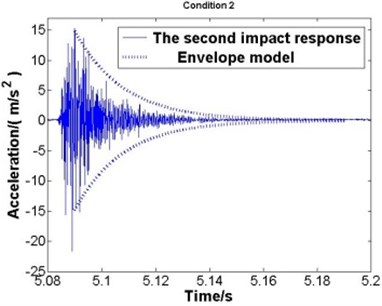
a) Condition 1
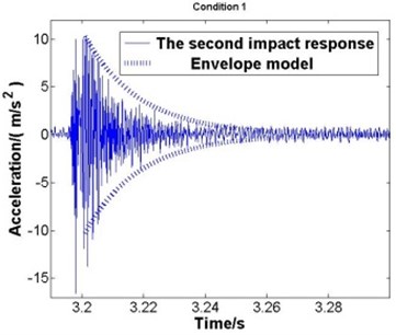
b) Condition 2
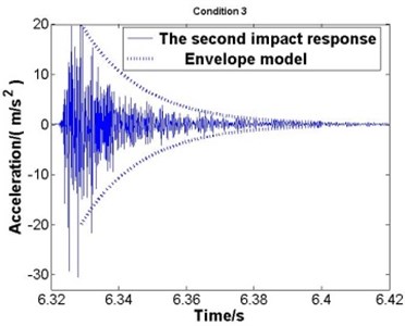
c) Condition 3
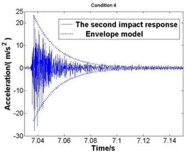
d) Condition 4
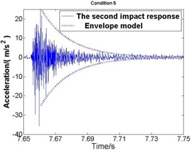
e) Condition 5
Where the solid line represents the second impact response and the dotted line represents the envelope model. According to the comparisons, good agreement is observed, which proves that the dynamics parameters got from the first impact is correct and the envelope model is applicable.
5. Adding a damping layer to restrain the vibration of manipulator
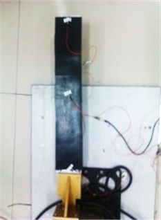
A sharp spike of acceleration arises in the first impact (Fig. 7). In order to restrain the vibration, a damping layer is added to the surface of the manipulator [13] (Fig. 8). The manipulator is controlled at the rotational speed on five working conditions as shown in Table 1 to do the experimental test.
Fig. 7Existing a sharp spike
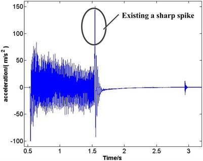
Fig. 8The manipulator with a damping layer
The sharp spikes of manipulator with a damping layer and without a damping layer are compared in different measuring points under different conditions (as shown in Fig. 9). X-axis represents rotational speed and y-axis represents acceleration value.
Fig. 9Comparing the sharp spikes
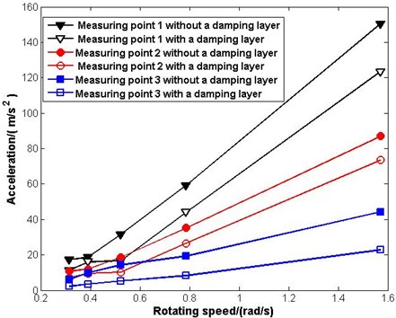
Where the first black line represent the sharp spikes of measuring point 1 without a damping layer in different rotating speed, the second black line represents measuring point 1 with a damping layer and the two lines make a comparison. Similarly, the two red lines make the comparison of measuring point 2 without a damping layer and with a damping layer and the two blue lines make the comparison of measuring point 3. Therefore, a conclusion can be obtained that adding a damping layer can suppress the vibration of the manipulator through the above comparisons.
6. Conclusions
Experimental study on the vibration behavior of a rotating manipulator during rotating and scamming process has been made. Repeated impact phenomenon is found in the scramming process of the manipulator. Conclusions obtained are as follow: (1) Dynamics parameters of the rotating manipulator are identified by the feature extraction of the first impact; (2) Using hammer experiment verifies the natural frequency correct; (3) Based on these dynamics parameters, an envelope model of the second impact response is established, and the applicability of the model is validated by experiments; (4) A sharp spike of acceleration arises in the first impact. A damping layer added to the surface of the manipulator is used to suppress the vibration, and via the experimental verification, the damping layer takes a certain effect on the vibration elimination.
References
-
Lovchik C. S., Diftler M. A. The robonaut hand: a dexterous robot hand for space. IEEE International Conference on Robotics and Automation, Vol. 2, 1999, p. 907-912.
-
Parrish J. C. The ranger telerobotic flight experiment: a teleservicing system for on-orbit spacecraft. Telemanipulator and Telepresence Technologies III, In Proceedings of the SPIE, 1996, p. 177-185.
-
Zizeng Pei The active vibration control of piezoelectric intelligent cantilever beam. Shanxi, Master’s thesis of Xi’an Electronic and Science University, 2011.
-
Lane J. S.,Dickerson S. L. Contribution of passive damping to the control of flexible manipulators. Proceedings of the International Computers in Engineering Conference, 1984, p. 175-180.
-
Alberts T. E., Dickerson S. L., Book W. J. On the transfer function modeling of flexible structures with distributed damping. ASME, Vol. 3, 1986, p. 23-30.
-
Sakawa Y. Modeling and feedback control of flexible arm. Journal of Robotics System, Vol. 2, Issue 4, 1985, p. 453-472.
-
Bailey T. L., Hubbard J. E. Distributed piezoelectric-polymer active vibration control of a cantilever beam. Journal of Guidance, Control, and Dynamics, Vol. 8, Issue 5, 1985, p. 605-611.
-
Plump J. M., Hubbard J. E., Bailey J. T. Nonlinear control of a distributed system: simulation and experimental results. Journal of Dynamic Systems, Measurement and Control, Vol. 109, Issue 5, 1987, p. 133-139.
-
Wei Sun, Fei Qi, Qingkai Han Identify the damping characteristics of hard coating composite structure based on envelope method of free vibration signal attenuation. Vibration and Shock, Vol. 32, Issue 12, 2013, p. 50-54.
-
Yimin Zhang, He Li Fundamentals of mechanical vibration. Beijing, Higher Education Press, 2010, p. 19-25.
-
Xingwei Guo Research on filtering technology of accelerometer signal. Science and Technology Innovation Herald, Vol. 22, 2008, p. 004.
-
Yunpeng Cui, Hongxia Pan, Zhijun Wang Analysis and study of a machine gun’s experimental modal based on experimental bench. Machinery Design and Manufacture, Vol. 3, 2013, p. 146-148.
-
Zhiyi Ning, Shaohui Du, Qingkai Han Effectiveness research of simulating blade gas shock and coating damping. Aeroplane, Vol. 39, Issue 5, 2013, p. 14-17.
About this article
This work was supported by the National Science Foundation of China (Grant No. 51105064); the National Program on Key Basic Research Project (Grant No. 2012CB026000); and the Natural Science Foundation of Liaoning Province (Grant No. 201202056).
