Abstract
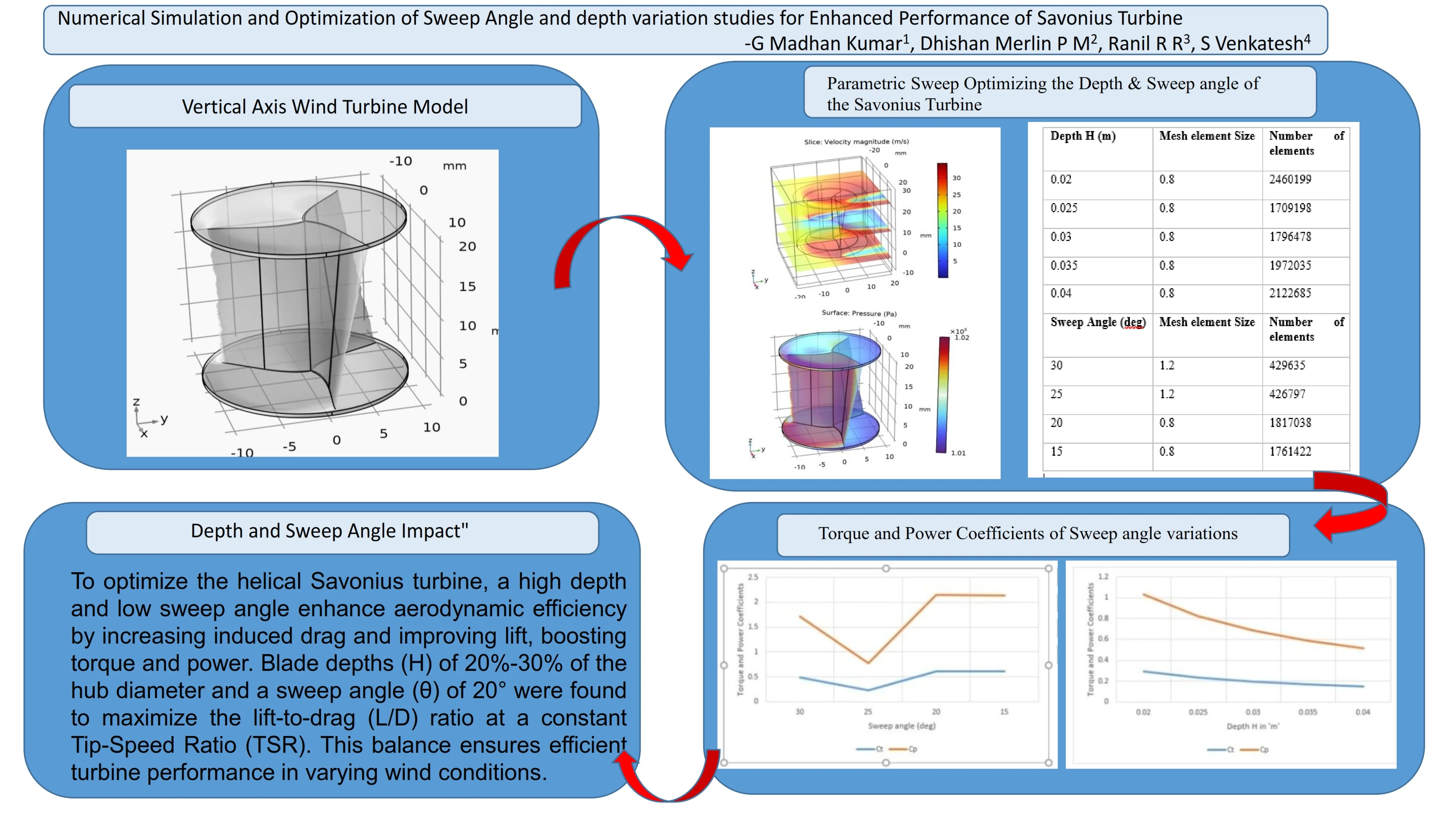
The straightforward and dependable Savonius turbine has a lot of promise for capturing wind energy in low-speed settings. However, poor aerodynamic performance frequently restricts its effectiveness. This study uses numerical modeling methods to examine how different sweep angles with constant depth affect Savonius turbine performance. The turbine's aerodynamic behaviour, torque production, and power coefficient were examined using parametric sweep optimization in various sweep angle with constant depth and fixed sweep angle with variable depth configurations. The results highlight the influence of sweep angle and depth on flow characteristics, lift to drag ratio, Torque and Power coefficient, leading to an optimized design with enhanced energy conversion efficiency. The findings provide valuable insights into improving the aerodynamic performance of Savonius turbines, contributing to their viability in sustainable energy applications.
Highlights
- Effect of Sweep Angle and Depth: Torque and power coefficients varied inconsistently with sweep angle changes but showed a consistent decline with increasing depth at a constant TSR of 3.5.
- Optimized Blade Design: Higher blade depth (20–30% of hub diameter) and a lower sweep angle (20°) enhanced aerodynamic efficiency by increasing induced drag and lift.
- Lift Enhancement Mechanism: Additional induced drag generated vortex buildup, improving blade lift characteristics and boosting turbine performance.
- Aerodynamic Performance: Moderate sweep angles combined with larger depth angles demonstrated superior aerodynamic behavior, enhancing torque and power coefficient.
- Steady-State Performance: The turbine operated optimally at a TSR of 3.5 under steady wind conditions, validating the design approach.
- Future Research Direction: Further studies should analyze torque and power variations over a broader TSR range to optimize performance under dynamic wind conditions.
1. Introduction
Savonius and Darrieus are the two main variations of VAWTs. While Savonius turbines are the subject of this paper, an explanation of the distinction between the two is needed. Although they both revolve around vertical axes, their physics are highly dissimilar. Long airfoil structures that rotate due to lift forces are known as Darrieus rotors. Darrieus turbines are comparable to HAWTs, at least in terms of lift. Wind drag forces power Savonius rotors. As a result, they look completely different from their lift-driven counterparts. A Savonius rotor’s most basic design involves cutting a cylinder in half and balancing the two halves around a central axis of rotation. Recent study uses DOE, simulations, and experiments to optimise the design of Savonius turbine blades, and the OR0.109BS2BN2 model improves Cp by 22.8 % [1]. The blade profile, guide gaps, and overlap ratio are important variables. For increased efficiency, future studies might look into hybrid turbine designs. The Savonius rotor design was optimised in recent work using response surface approach with FFD and FCCD, revealing important impacts of overlap (, ) and blade curvature (E, R) [2]. By comparison, the optimised blade profile outperformed the traditional design by 36.5 % ( = 0.2661) ( = 0.195). Helical Savonius VAWTs at 6, 8, and 10 m/s wind speeds are analysed using COMSOL, with an emphasis on rotor shape and Bach section effects [3]. In comparison to the original design, the Bach-developed variant that was optimised demonstrated better performance, less flow separation, and more torque, particularly at 6 m/s at tip speed ratios. Increases in turbulence had less of an impact on performance. Using ANSYS-Fluent and the Taguchi Method, this work creates and models a unique blade profile that improves drag/lift coefficients over the Savonius blade by 65 % [4]. By reducing aerodynamic instability by 93 %, the Novel Blade decreased noise and oscillation. A full-scale prototype will be tested in a wind tunnel and the winglet design will be improved in further work. There are studies chose semi-circular blades for stability and optimised environmentally friendly Savonius turbines using recyclable materials [5]. The best results were obtained with AR 4.5 and OR 1/6. Stable multi-rotor configurations were guaranteed by the 2D rotor spacing; further research is advised for changeable wind directions. The design of Savonius rotors has advanced, and this study examines these changes and how they affect performance. Improvements in Cp employing elliptical designs, helical forms, blade thickness, and three-fourth spline adjustments are among the main findings; increases range from 4 % to 20 %, depending on TSR [6]. Optimal designs minimise negative drag and improve flow behaviour. Using AR and OR parameters, this study optimised the S-RS wind turbine, with the greatest results obtained at AR = 0.848 and OR = 0.068 [7]. Rotor efficiency was increased by varying the overlap distance and raising AR at low values. The performance of a helical Savonius rotor with a 45° twist angle is examined in this study, along with that of modified and regular rotors [8]. Outperforming the other designs, the redesigned helical rotor with twist demonstrated a 26.4 % performance gain, the greatest of 0.22, and positive torque coefficients across all rotor angles. Few researchers uses semi-circular Savonius rotors and recycled cloth to create environmentally friendly urban wind turbines [9]. According to CFD models, the semi-circular rotor provides steady power generation, while turbines placed two degrees apart maintain efficiency. With a power coefficient close to 0.4, the study demonstrates enhanced performance in a Savonius turbine with damaged blades [10]. Additional mechanisms, however, raise the energy consumption and design complexity. To solve simulation problems and mechanical losses, more work is required. Performance-wise, the Ugrinsky wind turbine outperforms the Savonius turbine by 54.5 %. Power efficiency is increased by optimising blade size and TSR values; additional enhancements can be made by modifying the forms and geometry of the blades [11]. Some study adds a secondary blade to enhance Savonius VAWT performance. While increasing the distance between blades decreases torque, increasing the height of the secondary blade increases it [12]. Researchers uses CFD simulations in ANSYS to add fins to enhance the Savonius rotor’s performance (13). Based on the information, the power coefficient () is increased by 8.8 % when one fin is added and by 13.8 % when two fins are added. The 2-fin setup has a 5 % higher Cp than when no fins are used.
The effect of twist and tilt angles on an elliptical Savonius turbine rotor (ESTR) with wavy blades is investigated in this work [13]. The power coefficients of the models with 30° twist and 12° tilt angles increased by 3.7 % and 14.55 %, respectively. In order to maximise the Savonius VAWT’s performance, this study analyses variables such as arc angle, overlap ratio, and blade number using 3D-CFD simulations [14]. The best configurations for increased torque and efficiency are among the main conclusions, and the results encourage the adoption of hybrid power systems. Researchers studied, CFD was used to analyse a two-blade Savonius turbine with a disruptor cylinder [15]. The outcomes demonstrate enhanced performance and increased drag at reduced flow rates. Researchers studied investigates how a triple-blade Savonius turbine is affected by secondary blades, blade spacing, slot width, and radius [16]. The findings show that while raising the secondary blade radius improves performance, a 6 mm blade distance and a 16 mm slot width maximise torque. In order to determine the ideal torque values, this study optimises the Darrieus VAWT design using SolidWorks Flow Simulation, adjusting the rotor size, chord length, and pitch angle [17]. By modifying the distances at which blades overlap, this study maximises the performance of Savonius turbines [18]. Power and torque were increased by 7.5 % and 11.5 %, respectively, with the ideal vertical overlap of –0.1 and horizontal overlap of +0.15. This design will be applied to an oscillating water column system in future research, and structural forces will be examined. The ideal torque () and power () coefficients can be found by this study analyses four Savonius rotor topologies using 3D CFD simulations [19]. With a of 0.18 and consistent values between 0.25 and 0.35, the helical rotor exhibits the greatest performance and excellent efficiency. With a of 0.073, the 3-blade rotor performs the worst.
2. Research methodology
2.1. Mathematical modeling
The frozen rotor technique is thus supported by the Rotating Machinery, Fluid Flow interfaces. The frozen rotor method makes the assumption that the flow in the rotating domain is completely developed and represented by the rotating coordinate system.
The frozen rotor model then reduces to:
The frozen rotor is an equation form as well as a study type. The Rotating Machinery, Fluid Flow interfaces efficiently solve Eqs. (1) and (2) as “rotating” domains when a rotating machinery model is solved using a Frozen Rotor study step; nevertheless, “rotating” domains do not rotate at all. The domains stay stationary, or frozen, in place, but boundary conditions are still changed as though they were spinning. The Rotating Machinery, Fluid Flow interfaces solve for the velocity vector in the stationary coordinate system, , instead of , as in the time-dependent case.
The parameter TIME, which is defined in the Parameters node under Global Definitions, is by default set to zero in the Frozen Rotor research stage in order to make Eqs. (1) and (2) equivalent. It is altered by:
evaluates to its right value because is a function of TIME and TIME is a parameter. Ultimately, 0, and the velocity’s mesh time derivative is substituted with:
The usual, stationary Navier-Stokes equations are solved in nonrotating domains.
The resulting equation system is solved using a stationary solution in the Frozen Rotor research step. In certain situations, the frozen rotor method might provide the same result as solving Eqs. (1) through (2) to reach a steady state. The model is invariant with regard to the position of the rotating domain relative to the nonrotating domain, or the entire geometry may be rotating, for instance. The latter applies to a fan positioned in the center of a cylindrical, straight duct. A Frozen Rotor study step only includes interfaces that specifically support frozen rotors.
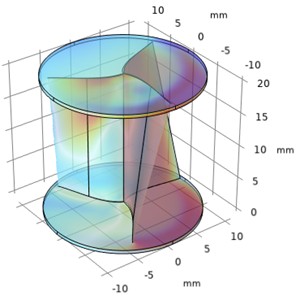
2.2. Meshing
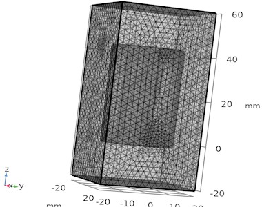
Select a suitable geometry for both the stationary and rotating domains. Establish boundary conditions (such as inlet velocity and non-slip barriers) and governing equations (such as Navier-Stokes for fluid flow). For rotational domains, use structured (swept) meshes; for stationary regions, use unstructured (tetrahedral) meshes as shown in Fig. 1. For precise interpolation, make sure that transitions at the rotating-stationary interface are seamless. For crucial locations, use boundary layer meshing and local refinement. Configure the frozen rotor study type and the spinning machinery physics interface. Set up solvers with the proper limits and provide coupling criteria between domains are shown in Table 1. Examine pressure contours, flow fields, and performance indicators (such as torque). Check findings against theoretical or experimental facts.
Table 1Mesh set up solver
Description | Value |
Mesh vertices | 494409 |
Tetrahedra | 2276535 |
Pyramids | 8904 |
Prisms | 174760 |
Triangles | 110556 |
Edge elements | 3981 |
Vertex elements | 58 |
Number of elements | 2460199 |
Minimum element quality | 0.01243 |
Average element quality | 0.6786 |
Element volume ratio | 6.9372E-8 |
Mesh volume | 1.275E5 mm³ |
Fig. 1Meshing of rotating domain and fluid domain
2.3. Parametric sweep optimization
Describe the physics and geometry of a frozen rotor simulation that includes both stationary and spinning domains. Choose the parametric sweep’s angle parameters, such as the inlet guide vane angles, rotating orientation, and blade pitch angle. Produce top-notch meshes for both spinning and stationary domains. To preserve accuracy, make sure the meshing is constant throughout the interface. Where necessary, use boundary layer meshing to address flow close to walls. Define the sweep variable in degrees or radians, such as the blade inclination or rotational angle. Decide on the depth of the blade and interval range (e.g., 0.02 m-0.04 m) as shown in Table 2. Make sure the model is parameterised so that changes in angle can dynamically modify the boundary conditions and shape. Use COMSOL’s parametric sweep tool in conjunction with the frozen rotor configuration. To guarantee smooth convergence in any scenario, solve the system for every angle in the sweep. To control computational costs, use effective solvers with adjustable tolerances. Examine torque, pressure distributions, flow fields, and other parameters for every angle. Plots and graphs can be used to visualise trends, such as how performance varies with angle. To determine the best angle for efficiency or performance, compare the outcomes.
Table 2Parametric sweep optimization for depth h and sweep angle with appropriate mesh element size
Depth (m) | Mesh element Size | Number of elements | Sweep angle (deg) | Mesh element size | Number of elements |
0.02 | 0.8 | 2460199 | 30 | 1.2 | 429635 |
0.025 | 0.8 | 1709198 | 25 | 1.2 | 426797 |
0.03 | 0.8 | 1796478 | 20 | 0.8 | 1817038 |
0.035 | 0.8 | 1972035 | 15 | 0.8 | 1761422 |
0.04 | 0.8 | 2122685 | – | – | – |
3. Numerical investigation – optimizing depth variation and sweep variation
3.1. Parametric sweep optimizing the depth of the Savonius turbine
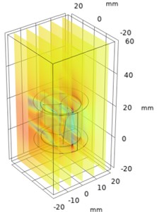
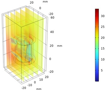
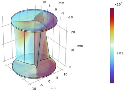
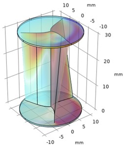
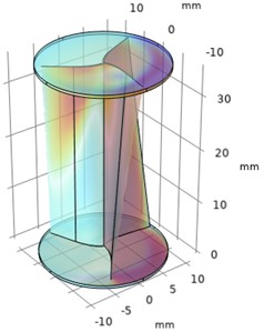
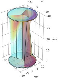
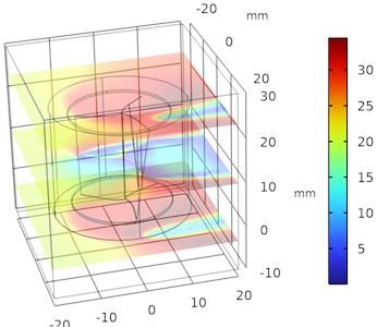
A parametric sweep is a methodical approach to studying how varying a single parameter, like the depth of a Savonius turbine, impacts its performance. This technique is useful in optimizing turbine design to maximize efficiency, torque, or power output. The depth, , is typically expressed as a function of the rotor diameter or chord length. Set a range of depth values, e.g., 0.3 to 0.6 (where is the rotor radius), based on the standard design configurations. Set consistent wind speeds, atmospheric pressure, and models of turbulence (such as - or - models). The velocity variations for different depth is plotted and the variation in velocity is improved with increase in depth as shown in Fig. 2.
Fig. 2Numerical investigation of velocity variations in helical parametric sweep angle
a) Time = 0 s, 0.02 m
b) Time = 0 s, 0.025 m
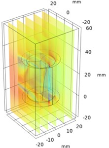
c) Time = 0 s, 0.03 m
d) Time = 0 s, 0.035 m
e) Time = 0 s, 0.04 m
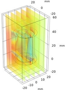
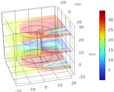
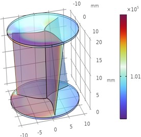
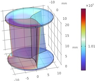
Similarly, the pressure contours of the exterior wall of the Savonius Turbine is plotted for various depth parametric sweep optimization process with respect to frozen rotor model which is shown in Fig. 3.
From Figs. 2 and 3 it was observed that the pressure decreases as the depth of the blade at constant sweep angle increases and the velocity increases as the depth of the blade at constant sweep angle increases. The optimal velocity is about 35 m/s and pressure is about 1 bar maintained around the upper half of the regions of helical turbine.
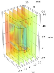
3.2. Parametric sweep optimizing the sweep angle of the Savonius turbine
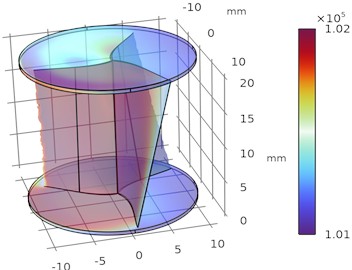
The sweep angle of a Savonius turbine refers to the angular extent of the blade curvature, which significantly influences the aerodynamic performance, torque, and efficiency of the turbine. Optimizing this parameter through a parametric sweep ensures the turbine performs optimally under specific operational conditions. The velocity variations for different sweep angle are plotted and the variation in velocity is accelerated with decrease in sweep angle as shown in Fig. 4. Similarly, the pressure contours of the exterior wall of the Savonius Turbine is plotted for various sweep angles under parametric sweep optimization process with respect to frozen rotor model which is shown in Fig. 5.
Fig. 3Numerical investigation of pressure drop and pressure rise in Helical sweep angle
a) Time = 0 s, 0.02 m
b) Time = 0 s, 0.025 m
c) Time = 0 s, 0.03 m
d) Time = 0 s, 0.035 m
e) Time = 0 s, 0.04 m
Fig. 4Illustrates the velocity variations in Helical sweep angle

a) 30°

b) 25°
c) 20°
d) 15°
Fig. 5Illustrates the pressure drop and pressure rise in Helical sweep angle
a) 30°
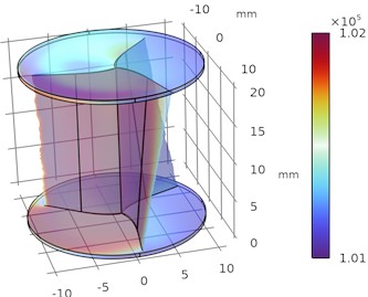
b) 25°
c) 20°
d) 15°
From Figs. 4 and 5 it was observed that the pressure decreases as the sweep angle of the blade at constant depth decreases and the velocity increases as the sweep angle of the blade at constant depth decreases and flow separation exceeds at the boundary layer wall thickness. The optimal velocity is about 35 m/s and pressure is about 1 bar maintained around the upper half and lower half of the regions of helical turbine.
4. Results and discussion
The torque coefficient symbolizes the proportion of the turbine’s torque to the wind energy that is accessible:
where: is torque coefficient, is torque (Nm), is rotational speed (rad/s), is density of air (kg/m³), is surface area (m²), is wind speed (m/s).
The ratio of the turbine's power output to the available wind energy is known as the power coefficient:
where: is power coefficient, is power output (W), is density of air (kg/m³), is surface area (m²), is wind speed (m/s).
The coefficients of torque and power for the different sweep angle with constant TSR of 3.5 and constant depth Savonius helical turbine was calculated and plotted in Fig. 6. Similarly, the coefficients are plotted for variable depth with constant TSR of 3.5 and constant sweep angle Savonius helical turbine which is shown in Fig. 7.
Fig. 6Torque and power coefficients of sweep angle variations
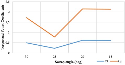
Fig. 7Torque and power coefficients of depth H variations
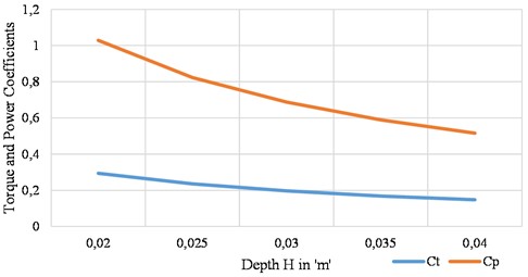
From Figs. 6 and 7, the torque and power coefficients are inconsistent in sweep angle variations at constant wind speed, but it was consistent and decreases in depth variations at same constant wind speed. To enhance the aerodynamic efficiency of the helical Savonius turbine, it is essential to design the blades with an optimized combination of high depth and a lower sweep angle. This specific configuration enables the generation of additional induced drag, which in turn augments the blade's lift characteristics. The increased lift contributes significantly to improved turbine performance by enhancing torque and power output.
To achieve a higher lift-to-drag (/) ratio at a constant Tip-Speed Ratio (TSR), the design was validated using blade depths () within the range of 20 % to 30 % of the hub diameter. Additionally, the optimal aerodynamic behavior was observed at a sweep angle () of 20°. This balance between depth and sweep angle effectively maximizes the aerodynamic advantage, providing a solid foundation for efficient turbine operation across various wind conditions.
5. Conclusions
The study examined the effects of varying sweep angles and depth angles in different configurations of Savonius helical turbine blades. Based on the velocity and pressure plots, it was observed that blades with a moderate sweep angle paired with a larger depth angle demonstrated improved aerodynamic performance. This configuration generated additional lift, which was attributed to the increased induced drag caused by vortex buildup in the upper and lower halves of the helical blade. This aerodynamic phenomenon, when combined with the blade's attachment to a circular drum, contributed to the development of torque and improved the power coefficient.
Using a Tip-Speed Ratio (TSR) of 3.5, the vertical axis wind turbine operated optimally under steady wind conditions. However, to comprehensively understand and optimize the performance of Savonius helical turbines, further studies are recommended. Future research should explore the variations in torque and power coefficient across a wider range of TSR values. This would provide insights into the behavior of the turbine under dynamic wind conditions and facilitate the design of more efficient configurations for diverse operating environments.
References
-
K. A. H. Al-Gburi, F. B. I. Alnaimi, B. A. J. Al-Quraishi, E. S. Tan, and A. K. Kareem, “Enhancing Savonius vertical axis wind turbine performance: a comprehensive approach with numerical analysis and experimental investigations,” Energies, Vol. 16, No. 10, p. 4204, May 2023, https://doi.org/10.3390/en16104204
-
Al Quraishi and Mohammed Baqer Zaki Yahya, “Taguchi optimization of water Savonius turbine for low-velocity inlets using CFD approach,” Journal of Energy and Safety Technology (JEST), Vol. 6, No. 1, pp. 1–7, Jun. 2023, https://doi.org/10.11113/jest.v6n1.137
-
C. Yiğit, “Optimization of the S-rotor Savonius wind turbine,” Sakarya University Journal of Science, Vol. 24, No. 6, pp. 1216–1222, Dec. 2020, https://doi.org/10.16984/saufenbilder.780890
-
M. N. Zadeh, M. Pourfallah, S. S. Sabet, M. Gholinia, S. Mouloodi, and A. T. Ahangar, “Performance assessment and optimization of a helical Savonius wind turbine by modifying the Bach’s section,” SN Applied Sciences, Vol. 3, No. 8, Jul. 2021, https://doi.org/10.1007/s42452-021-04731-0
-
Z. Mao and W. Tian, “Effect of the blade arc angle on the performance of a Savonius wind turbine,” Advances in Mechanical Engineering, Vol. 7, No. 5, May 2015, https://doi.org/10.1177/1687814015584247
-
Anum, “Investigation on the enhancement of the performance of the Savonius rotor depends on partial differential equation,” International Journal of Innovative Research in Science, Engineering and TechnologyISO Certified Organization, Vol. 2, No. 8, pp. 4018–4023, 2007.
-
A. Snortland, O. Williams, and B. Polagye, “Influence of the downstream blade sweep on cross-flow turbine performance,” in Proceedings of the European Wave and Tidal Energy Conference, Vol. 15, Sep. 2023, https://doi.org/10.36688/ewtec-2023-391
-
M. J. G. Veloso, C. H. P. Dos Santos, J. R. P. Vaz, and A. M. Chaves Neto, “Quasi-steady analysis of a small wind rotor with swept blades,” Sustainability, Vol. 15, No. 13, p. 10211, Jun. 2023, https://doi.org/10.3390/su151310211
-
M. B. Salleh, N. M. Kamaruddin, and Z. Mohamed-Kassim, “Experimental investigation on the effects of deflector angles on the power performance of a Savonius turbine for hydrokinetic applications in small rivers,” Energy, Vol. 247, p. 123432, May 2022, https://doi.org/10.1016/j.energy.2022.123432
-
P. P. S. Lukitadi, P. A. Setiawan, and F. A. Firmansyah, “Simulation of overlap effect on Savonius wind turbine performance by varying cylinder distance in front of returning blade,” International Journal of Marine Engineering Innovation and Research, Vol. 8, No. 4, Dec. 2023, https://doi.org/10.12962/j25481479.v8i4.19364
-
B. Deda Altan and A. Gungor, “Improvement of Savonius wind turbine performance with using wind collector,” Scientia Iranica, May 2023, https://doi.org/10.24200/sci.2023.60454.6809
-
S. Farajyar, F. Ghafoorian, M. Mehrpooya, and M. Asadbeigi, “CFD investigation and optimization on the aerodynamic performance of a Savonius vertical axis wind turbine and its installation in a hybrid power supply system: a case study in Iran,” Sustainability, Vol. 15, No. 6, p. 5318, Mar. 2023, https://doi.org/10.3390/su15065318
-
H. Aboujaoude, F. Bogard, F. Beaumont, S. Murer, and G. Polidori, “Aerodynamic performance enhancement of an axisymmetric deflector applied to Savonius Wind turbine using novel transient 3D CFD simulation techniques,” Energies, Vol. 16, No. 2, p. 909, Jan. 2023, https://doi.org/10.3390/en16020909
-
K. A. H. Al-Gburi, B. A. J. Al-Quraishi, F. B. Ismail Alnaimi, E. S. Tan, and A. H. S. Al-Safi, “Experimental and simulation investigation of performance of scaled model for a rotor of a Savonius wind turbine,” Energies, Vol. 15, No. 23, p. 8808, Nov. 2022, https://doi.org/10.3390/en15238808
-
M. H. Mohamed, F. Alqurashi, A. Ramadan, and D. Thévenin, “Enhancement attempts for a three-bladed Savonius turbine performance,” Frontiers in Energy Research, Vol. 10, Apr. 2022, https://doi.org/10.3389/fenrg.2022.797868
-
Ramiz Ibraheem Saeed, Ahmed Al-Manea, Ahmed Khalid Ibrahim, and Dendy Adanta, “Numerical investigation on the effect of profile and blade numbers in a Savonius vertical axis wind turbine,” CFD Letters, Vol. 14, No. 9, pp. 75–88, Sep. 2022, https://doi.org/10.37934/cfdl.14.9.7588
-
B. Li, K. M. Dobosz, H. Zhang, J. D. Schiffman, K. Saranteas, and M. A. Henson, “Predicting the performance of pressure filtration processes by coupling computational fluid dynamics and discrete element methods,” Chemical Engineering Science, Vol. 208, p. 115162, Nov. 2019, https://doi.org/10.1016/j.ces.2019.115162
-
R. Norouztabar, S. S. Mousavi Ajarostaghi, S. S. Mousavi, P. Nejat, S. S. Rahimian Koloor, and M. Eldessouki, “On the performance of a modified triple stack blade Savonius wind turbine as a function of geometrical parameters,” Sustainability, Vol. 14, No. 16, p. 9816, Aug. 2022, https://doi.org/10.3390/su14169816
-
A. T. Ubando, R. San, and J. D. P. Cruz, “Savonius wind turbine numerical parametric analysis using space-filling design and gaussian stochastic process,” Wind, Vol. 2, No. 1, pp. 113–128, Feb. 2022, https://doi.org/10.3390/wind2010007
Cited by
About this article

The authors extend their sincere gratitude to Sathyabama Institute of Science and Technology for providing the resources and facilities necessary for the completion of this study. We are deeply grateful to our mentors and colleagues for their valuable insights and constructive feedback throughout this research. Special thanks are due to the Extrica Journal editorial team for their meticulous review and guidance, which significantly enhanced the quality of this manuscript. Lastly, the authors acknowledge the support of family, friends, and well-wishers, whose encouragement and belief in our work have been instrumental in bringing this research to fruition.
The datasets generated during and/or analyzed during the current study are available from the corresponding author on reasonable request.
G. Madhan Kumar: conceptualization, data curation, formal analysis, supervision, writing-review and editing. Dhishan Merlin P M: resources, software, validation, visualization, writing-original draft preparation. Rani R R: validation, visualization. S. Venkatesh: investigation, methodology, project administration, supervision, writing-review and editing.
The authors declare that they have no conflict of interest.
