Abstract
Shaft vibration and bearing vibration are important parameters reflecting the dynamic behavior of the rotor-bearing-supporting system, and they have a significant impact on the operating state and safety of equipment. However, obtaining relevant signals of shaft vibration or bearing vibration often faces many challenges in actual working conditions, mainly due to the limitations of measuring equipment, environmental interference, and the complexity of operating conditions. Therefore, understanding the correlation between shaft vibration and bearing vibration can not only realize signal complementarity and improve the comprehensiveness and accuracy of data, but also provide a more accurate basis for fault diagnosis and condition monitoring. Therefore, this study constructs an unbalanced fault dynamics model based on the short-bearing theory. The shaft vibration and bearing vibration signals predicted by the model are obtained through the numerical integration technique. Secondly, the full-vector spectrum technology based on homologous information fusion is adopted to conduct a two-channel fusion analysis of these signals. Finally, a rotor experimental platform is constructed and corresponding experimental verifications are carried out to verify the accuracy of these analysis results. The experimental results confirm that obtaining this complementary relationship enables us to infer the operation health state of equipment through the changing trend of some parameters even in the absence of a certain measurement signal, and then formulate corresponding maintenance and management strategies, thereby improving the reliability and operating efficiency of equipment.
1. Introduction
In the operation of modern mechanical equipment, shaft vibration and bearing vibration are key factors affecting the stability and reliability of equipment [1-2]. It is difficult to obtain relevant signals of shaft vibration and bearing vibration simultaneously due to the limitations of measuring points and the complexity of operating conditions. Therefore, it is particularly important to conduct in-depth research on the relationship between the shaft vibration and bearing vibration.
Consequently, many scholars have conducted a series of research on the relationship between shaft vibration and bearing vibration. Yang et al. emphasized the role of shaft vibration in the RSDB system and the coupling relationship between shaft vibration and other vibration modes, but lacked of comprehensive experimental verification [3]. Kuang et al. studied the mechanism of frictional vibration and the coupling process of shaft vibration, indicating that the current research on coupling mechanism of shaft vibration under unbalanced state is still imperfect [4]. Chen et al. proposed a new four-degree-of-freedom (4-DOF) bearing support model to predict and control shaft vibration more accurately, but there are relatively large prediction errors in some positions [5]. Yang et al. revealed the coupling vibration mechanism of the RSDB system, and proposed that the super-harmonic components of shaft torsional vibration and the combined frequency components of blade bending vibration and shaft bending vibration are all affected commonly [6], but the accuracy of detection indicators need to be improved. Chandrashekar et al. found that stainless steel for shaft materials is superior to low-carbon steel, but the research on the relationship between shaft vibration and bearing vibration is relatively one-sided and lacks of more extensive material comparison [7]. Wu et al. tested the bearing performance through shaft vibration experiments under different load conditions, and proposed that increasing the offset angle of the flexible structure is helpful to improve the running stability of the bearing-rotor system [8], but the research lacks of robustness and experimental data support. Yang et al. discussed the vibration of the shaft system and carried out shaft vibration coupling calculations [9], but lacked of comprehensive practical application verification. Xuan et al. showed that the friction between the rotor and the bearing causes high-order harmonic components within a certain frequency range in the shaft vibration spectrum, which may cause mechanical resonance section-start and reduce instability [10], but did not deeply explore the vibration source. Similarly, Yang et al. studied bearing vibration [11], but the model’ high complexity needs to be simplified. Ma et al. showed that optimizing the bearing structure can improve bearing vibration [12], but still needs to further improve the running stability. Duet al. studied bearing vibration and found that there is a rubbing phenomenon between the static and dynamic parts [13]. Zhufocused on the large shaft vibration phenomenon of steam-driven induced draft fans and solutions [14], but lacked of systematic verification and practical case support. Zhou found that the high shaft vibration is caused by the bearing bush paint film [15], but did not give a systematic solution. Xu et al. introduced the reasons for instability of shaft vibration signals, and found that the problem lies in the poor contact caused by dirty joints [16]. Wei et al. analyzed bearing vibration and found that the phenomenon of refusing to operate needs to be prevented [17]. Zhu et al. carried out a systematic study on the shaft vibration problem of the WX generator, and found that reducing the vibration value is of great significance [18]. Jia et al. fully utilized the measured shaft vibration and bearing vibration data to analyze and study the axis locus, the change of the journal center position, and the proportional relationship between shaft vibration and bearing vibration [19], but lacked of more extensive application verification. Ma et al. [20] studied the relationship between shaft vibration and temperature anomalies and found that the problem lies in insufficient sphericity and clearance. Li et al. [21] analyzed the impact of deep peak shaving conditions on shaft vibration, providing reference for similar fault analysis, but there is insufficient research on the causes of faults. Tian et al. [22] applied CEEMDAN, permutation entropy, and mathematical morphology to denoise shaft vibration signals, achieving better results than wavelet soft thresholding. Tao et al. [23] studied the effect of shaft vibration on tooth surface ripples by comparing them in the frequency domain, but there is insufficient in-depth research on the coupling mechanism.
In summary, many scholars have carried out a series of explorations and achieved certain results, but there are still some deficiencies. Firstly, most of them only considered single shaft vibration or bearing vibration for state monitoring or fault diagnosis, ignoring the importance relationship between them. Secondly, there is also a lack of support from multiple data sources, and single channel signal analysis will ignore the fusion of homologous information. To solve the above problems, this paper proposes the research on the relationship between shaft vibration and bearing vibration under the unbalanced state based on homologous information fusion. The research in this paper has the following specific contributions:
1) A more comprehensive dynamics model is constructed based on the short-bearing theory to better fit the actual working environment and better reflect the relationship between shaft vibration and bearing vibration under the influence of different parameter changes.
2) The homologous information fusion technology, also known as full vector spectrum technology is used to analyze the shaft vibration and bearing vibration signals to enhance the accuracy of fault diagnosis, which compensates for the potential information loss caused by traditional single channel information analysis methods.
3) A rotor experimental platform is constructed to verify the accuracy of the simulation model through actual experiment, improving the reliability of the research conclusions.
2. Theoretical basis
2.1. Full vector spectrum technology
Full vector spectrum technology was developed by the institute of vibration engineering, Zhengzhou University, which is an advanced vibration monitoring technology. The full vector spectrum technology regards the rotor whirling as the combined effect of multiple harmonic frequencies and observes that the rotor whirling path is elliptical at these frequencies. Based on this, this technology uses the semi-major axis of the elliptical trajectory as the main vibration vector, and takes the rotor whirling intensity at different harmonic frequencies as the key indicator for fault diagnosis. The full vector spectrum technology not only makes up for the deficiencies of the full spectrum and holospectrum technologies, but also comprehensively shows the rotor whirling state through parameters such as the main vibration vector, secondary vibration vector, vibration vector angle, and vector phase.
Since the steady-state whirling of the rotor in its plane can be regarded as a combination of several angular velocities, the motion differential equation of any whirling angular velocity ωi can be written as:
Among them, XiYi are the vibration amplitudes of the single-harmonic i in the x and y direction respectively, ϕxi and ϕyi are the phase angles of the single-harmonic i in the x and y direction respectively. Therefore, as for the center of a disk, the differential equation of motion for any vortex angular velocity can be written as:
Then Eq. (1) can be simplified as:
Make use of Euler's formula: e±jωt=cosωt±jsinωt. Then the complex form of Eq. (3) is:
Therefore, the equation of motion in the x and y directions can be written as:
Among them, ˉXi, ˉYi are the complex amplitudes of the single-harmonic wave i in the x and y directions respectively. Therefore, the equation of motion of the vibration component of any single-harmonic wave i can be obtained as:
Expand Eq. (6), and the following equation can be obtained:
Since both xi and yi should be real numbers in engineering. The real motion relationship of the node is shown in Fig. 1, from which it can be seen that the real motion of the node should be described as:
Among them, ϕxi=arctan(xsi/xci), ϕyi=arctan(ysi/yci).
Fig. 1Rotor node motion sketch
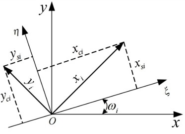
Fig. 2Shaft centerline movement trajectory diagram
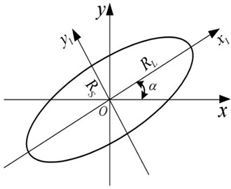
For Eq. (8), by eliminating the time parameter t, the elliptical trajectory equation of a single harmonic i can be obtained as:
Fig. 2 is the motion trajectory schematic diagram of the trajectory ellipse equation of the single-harmonic i. The semi-major axis RLi, semi-minor axis RSi of this ellipse, the angle α between the semi-major axis RLi and the x-axis, and the phase angle ϕi when the disc shaft center moves along its elliptical trajectory can be obtained by the method of analytic geometry. From the elliptical trajectory Eq. (9), the above-mentioned parameters can be obtained respectively as follows:
In kinematics, a motion along an elliptical trajectory can be regarded as the composition of two circular-trajectory component motions with the same frequency, and the precession directions of these two component motions are exactly opposite, which is shown in Fig. 3. Since any point on the ellipse can be represented by a point z(z=x+jy) in the complex plane, which can be obtained as following:
Among them, ˉxpi=xpci+jxpsi, ˉxri=xrci+jxrsi.
Fig. 3Axle center trajectory diagram of ellipse composed of two circles
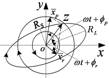
Let ϕpi, ϕri be the initial phase angles of the pro-precession circle and the anti-precession circle respectively, and let Xpi and Xri be the modulus of ˉxpi and ˉxri respectively, then the following relationships can be obtained:
And the real part xi and the imaginary part yi of point zi can be expressed in the following two forms:
Among them, ˉx*ri is the conjugate of ˉxri. From Eq. (6) and Eq. (12b), the following relations could be obtained:
Therefore, it can be solved from Eq. (13):
Then we can get:
From Eq. (11), the parametric relationship between this ellipse and the two positive circles can be obtained as:
Therefore, when Xp>Xr, the obtained synthetic trajectory has the same movement direction as the precession direction of the positive circle with radius Xp, this is called positive precession at this time. when Xp<Xr, the movement direction of the synthesized trajectory is the same as the precession direction of the positive circle with radius Xr, and this is reverse precession at this time. and when Xp=Xr, the synthesized trajectory is a straight line.
In summary, the full vector spectrum technology has significant advantages in analyzing the dynamic model under the unbalanced state: the traditional single channel signal analysis method is prone to misjudgment due to incomplete information, and the full vector spectrum technology can effectively fuse the vibration signals synchronously obtained from the two channels and ensure the completeness of information through the characteristics of main vibration vector.
2.2. Construction of the dynamic model under unbalanced state
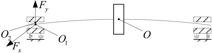
As shown in Fig. 4, it is a schematic diagram of a dynamic system under unbalanced state. This system is supported by two symmetrical sliding bearings. Among them, the center O of the disc has a mass of 2m, the connection between the journal and the disc is assumed to be a lightweight elastic shaft, and its elastic and damping characteristics are represented by coefficients K and C. The concentrated mass at the center O1 of the journal is m1, and the journal is subjected to the oil-film forces of the sliding bearing in the x-axis and y-axis directions, which are respectively recorded as Fx and Fy. The equivalent mass of the bearing pedestal center O2 is m2, and the elastic and damping characteristics in the horizontal and vertical directions between the bearing pedestal and the foundation are respectively represented by KX, CX, and KY, CY.
Fig. 4Schematic diagram of the dynamic model in unbalanced state
The dynamic oil-film force model of the sliding bearing is crucial for accurately evaluating the dynamic behavior of the dynamic system in unbalanced state. In traditional research, eight linearized stiffness and damping coefficients are usually used to describe the bearing oil-film force based on linear assumption. However, in practical applications, due to the influence of various factors such as bearing design, lubricating oil characteristics, rotor dynamics, and environmental factors, the oil-film force often exhibits obvious nonlinear characteristics. Therefore, we choose to use the Capone model to simulate and analyze the constructed dynamic system in unbalanced state. Under the theoretical framework of short bearing, the Reynolds equation can be simplified into a dimensionless form to facilitate analysis:
Among them: R is the bearing radius, L is the bearing length, h is the dimensionless oil-film thickness, that is h=ˉh/δ, ˉh is the oil – film thickness, δ is the radial clearance of the bearing, z is the dimensionless longitudinal coordinate of the bearing bush, that is z=ˉz/L, ˉz is the axial coordinate of the bearing bush, p is the dimensionless oil-film pressure, that is p=ˉp/6μω(R/δ)2, ˉp is the oil-film pressure, and μ is the lubricating oil viscosity, x and y represent the displacements in two directions in the plane coordinate system respectively, θ represents the angle between the displacements in the x and y directions. Then from Eq. (17), the dimensionless oil-film force p can be obtained as:
in which the meaning of each symbol is same as Eq. (17). Besides, D represents the bearing diameter. After integrating and simplifying Eq. (18), the short-bearing oil-film forces in the x and y directions in dimensionless form can be obtained respectively as following:
Among them:
is for the differential equations of motion of the system and dimensionless treatment. Suppose the displacements of the disc center in the directions are x and y respectively. The displacements of the shaft journal center in the x and y directions are x1 and y1 respectively. The displacements of the bearing housing center in the x and y directions are x2 and y2 respectively. The disc eccentricity is e, and the rotation angular velocity is ω. Then the model of the dynamic system in unbalanced state can be expressed as:
For the convenience of analysis , dimensionless treatment is carried out on Eq. (20): let τ=ωt, ψ=δ/R, fx=ψ2F/μωLR, fy=ψ2Fy/μωLR, e=√x2+y2, ε=e/δ=√X2+Y2, X=x/δ, ˙X=˙x/δω, Y=y/δ, ˙Y=˙y/δω, ¨Y=¨y/δω2, M1=m1δωψ2/μLR, M2=m2δωψ2/μLR, ηi=ki/miω2, ξi=ci/miω, G=g/δω2. Among them, μ is the lubricating oil viscosity, δ is the bearing clearance, τ is the dimensionless time, L is the bearing length, R is the bearing radius, g is the acceleration due to gravity, and G is the dimensionless gravitational load. Then, in the dimensionless case, Eq. (20) can be written as:
In actual production, the structural parameters of the equipment change with work loss and changes in the external environment, and all of these may affect the vibration characteristics of rotor system. Therefore, both theoretical research and practical applications must use the full of full vector spectrum technology to analyze the influence of system parameters on shaft vibration and bearing vibration in unbalanced state. Since the relative displacement signals in the horizontal and vertical directions measured at the shaft journal can be expressed as: dx=X1-X2, dy=Y1-Y2, and the velocity signals in the horizontal and vertical directions obtained at the bearing housing can be expressed as: vx=˙X2, vy=˙Y2, then the acceleration signals are ax=¨X2, ay=¨Y2 respectively. Based on Eq. (21), the relationship between shaft vibration signal and bearing vibration signal can be obtained as:
Because the dynamic oil film force of the sliding bearing has strong nonlinearity, it is difficult to obtain a satisfactory analytical solution. Therefore, the Runge-Kutta method is used to perform numerical simulation analysis on the dynamic model system in unbalanced state. The parameter values are set as follows: m= 32.1 kg, m1= 4 kg, m2= 50 kg, δ= 0.11 mm, L= 12 mm, d= 50 mm, μ=0.018 Pa⋅s, C=1050 N⋅s/m, Cx=450 N⋅s/m, Cy= 500 N⋅s/m, K=2.5×10⁷ N/m, Kx=2.0×10⁹ N/m, Ky=2.5×10⁹ N/m, g=9.81 N/kg, n= 1500 r/min. Therefore, the natural frequency of the rotor system can be obtained as ωn=√k/m= 624 rad/s.
Fig. 5Flow chart of the study
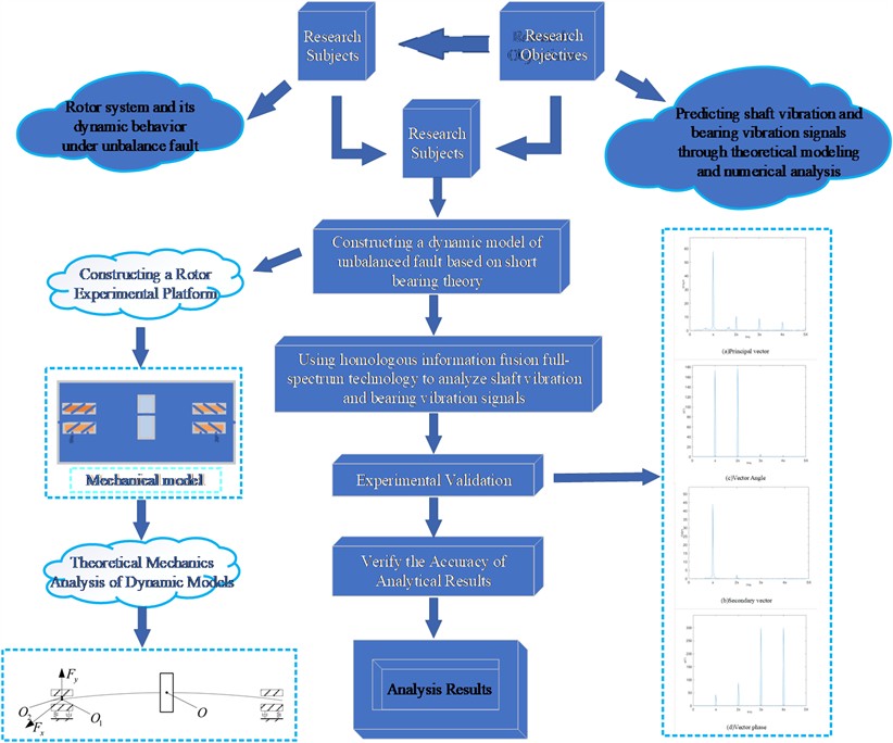
3. Research process on the relationship between shaft vibration and bearing vibration of rotor system under unbalanced state
This study systematically explores the relationship between shaft vibration and bearing vibration in rotor systems under unbalanced conditions. The research includes a complete process from theoretical model construction to experimental verification. The specific steps of the study as shown in Fig. 5 are as follows:
1) Initiate research process: Clarify research objectives and requirements and determine the relationship between shaft vibration and bearing vibration under unbalanced conditions.
2) Establish a dynamic model under unbalanced state based on the theory of short bearings.
3) The Runge Kutta method is used to solve the model equations and predict the dynamic response of the rotor system.
4) Introduce the full vector spectrum technology to comprehensively analyze multi-channel homologous signal data and gain a deeper understanding of the characteristics of vibration.
5) Build a rotor experimental platform, conduct systematic experiments to collect data, and compare it with theoretical simulation predictions to verify the accuracy of the proposed method.
4. Results and analysis
4.1. The variation of eccentricity e on the shaft vibration and bearing vibration
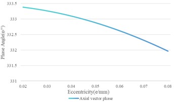
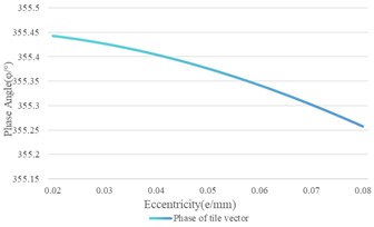
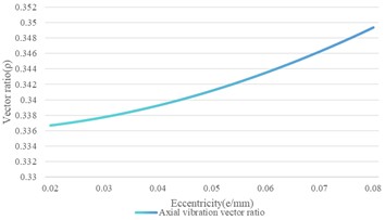
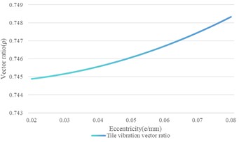
By building a dynamic model and keeping other system parameters constant, simulation was conducted to investigate the impact of eccentricity variation on the shaft vibration and bearing vibration. The variation of eccentricity e ranges from 0.02 mm to 0.08 mm. The specific results are shown in Fig. 6, based on which it can be observed that the main and secondary vibration vectors increase linearly with the increase of eccentricity distance. The growth rate of the main vibration vector is approximately 1.10003, and the growth rate of the secondary vibration vector is approximately 0.390704. Due to the different growth rates of the main and secondary vibration vectors, the vibration ratio exhibits a mild nonlinear increase with the increase of eccentricity distance. The angle of the axial vibration vector slightly decreases with the increase of eccentricity distance. However, in practical applications, this change is small, and it can be considered that the vibration vector angle remains roughly stable. It could be observed that the main and secondary vibration vectors increase linearly with the increase of eccentricity based on Fig. 6, indicating that the intensity of vibration increases with the increase of eccentricity. The vibration vector ratio also increases with the increase of eccentricity, further indicating the enhancement of vibration intensity. Contrary to the trend of the main and secondary vibration vectors, the vibration vector angle and phase decrease with increasing eccentricity, which may mean that the phase angle of the vibration decreases with increasing eccentricity.
In all, it can be seen that both the main and secondary vibration vectors increase with the increase of eccentricity, whether it is the shaft vibration signal or the bearing vibration signal. The vibration vector ratio and vibration vector angle show different change trends. The vibration vector angle of the shaft vibration signal is relatively stable, while the vibration vector angle and phase of the bearing vibration signal decrease with the increase of eccentricity. Besides, it can also be seen that the rate of change of the main and secondary vibration vectors of the shaft vibration signal is greater than that of the bearing vibration signal, indicating that the influence of eccentricity on the shaft vibration signal is more significant. Besides, this also indicates that the shaft vibration is more sensitive to the change of eccentricity, and this characteristic could be used in engineering application, for example, when the shaft vibration changes significantly more than the amplitude of the bearing vibration change, more attention can be paid to eccentricity related faults, such as rotation looseness and collision wear fault. The variation rate of the shaft vibration signal changing with eccentricity is greater than that of the bearing vibration signal, and the vector ratio of the shaft vibration signal is always greater than that of the bearing vibration signal. This may mean that the trajectory ellipse synthesized by the bearing vibration velocity signal is closer to a circle, while the true vortex trajectory ellipse of the shaft is flatter. At different eccentricities, the vibration vector angle of the bearing is generally smaller than that of the shaft. Although their values differ greatly, their changing trends are similar.
Fig. 6The variation of eccentricity on the shaft vibration and the bearing vibration
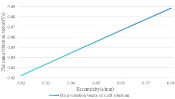
a) Shaft vibration main vibration vector
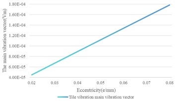
b) Bearing vibration main vibration vector
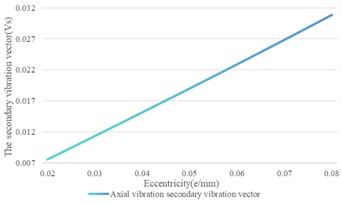
c) Shaft vibration secondary vibration vector
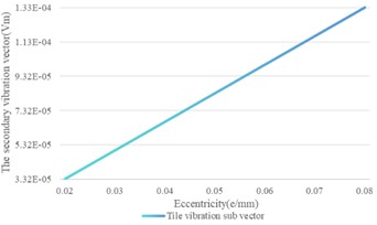
d) Bearing vibration secondary vibration vector
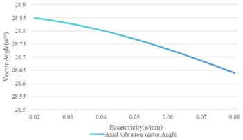
e) Shaft vibration vector angle
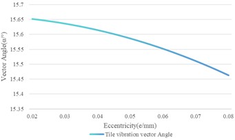
f) Bearing vibration vector angle
g) Shaft vibration vector phase
h) Bearing vibration vector phase
i) Shaft vibration vector ratio
j) Bearing vibration vector ratio
4.2. The influence of disk mass changes on the shaft vibration and bearing vibration
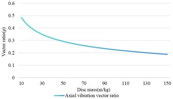
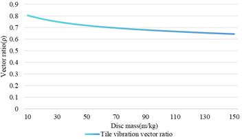
In the study, a series of simulation experiments were conducted using the designed dynamic model within the range of disk mass changing from 10 kg to 150 kg.
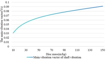
Based on Fig. 7, it can be observed that the main vector of shaft vibration signal increases with the increase of the disk mass, and its trend tends to be stable when the mass exceeds 30 kg. The secondary vibration vector reaches its peak at a mass of 30 kg and then decreases with increasing of mass. The vibration vector ratio decreases with increasing of mass, indicating that the elliptical shape of the rotor trajectory becomes flatter with increasing of disc mass. The vector angle decreases with the increase of disk mass, and the variation between 10 kg and 150 kg exceeds 10°. The main and secondary vibration vectors of the bearing vibration signal show a similar change trend. The aspect ratio gradually decreases with the increase of mass. There is a strong nonlinear relationship between the vector angle and the mass of the disk. When the mass is less than 30 kg, the vector angle increases rapidly, then gradually decreases and tends to be stable.
Fig. 7The influence of disk mass change on shaft vibration and bearing vibration
a) Shaft vibration main vibration vector

b) Bearing vibration main vibration vector
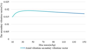
c) Shaft vibration secondary vibration vector
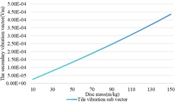
d) Bearing vibration secondary vibration vector
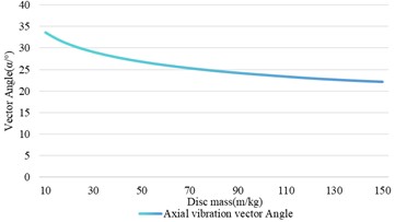
e) Shaft vibration vector angle
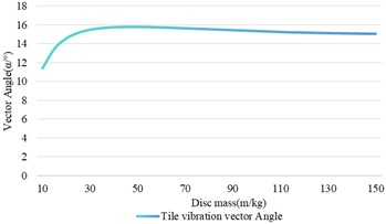
f) Bearing vibration vector angle
g) Shaft vibration vector phase
h) Bearing vibration vector phase
By comparing the shaft vibration signal and the bearing vibration signal, we can find that although the main vibration vectors of both increases with the increase of disk mass, the trend of the shaft vibration signal’ main vibration vector tends to flatten when the mass increases, while the bearing vibration signals’ main vibration vector maintains a stable linear change. The variation trend of the secondary vibration vector of shaft vibration and bearing vibration is completely different. The secondary vibration vector of shaft vibration shows nonlinear changes after reaching its maximum value at 30 kg, while the secondary vibration vector of bearing vibration continues to increase. The similar trends in the variation of the vector ratio between shaft vibration and bearing vibration indicate that monitoring the changes of vector ratio is crucial for studying the relationship between shaft vibration and bearing vibration.
4.3. The influence of changes in support stiffness on the shaft vibration and bearing vibration
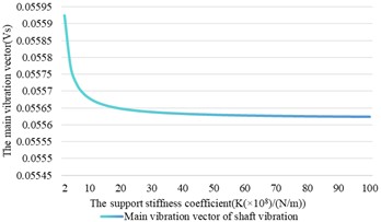
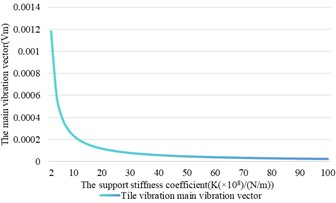
When conducting simulation analysis, we set a condition that the system is isotropic, which means that the support stiffness coefficients in the x and y directions are equal. Specifically, when the support stiffness coefficient Kx=Ky varies between 2.0×10⁸ N/m and 1.0×10¹⁰ N/m, the damping coefficient Cx=Cy=500 N·s/m. Under these conditions, we kept all other parameters being constant to observe and analyze the dynamic response of the system at different support stiffnesses.
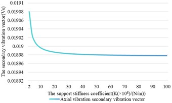
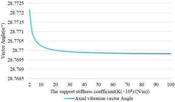
In Fig. 8, it can be seen that both the main and secondary vibration vectors of the shaft vibration signal show a decreasing trend with the change of support stiffness, and this decrease is not linear. This phenomenon can be understood as a decrease in the amplitude of system vibration while increasing the support stiffness. As the support stiffness increases, the vibration vector ratio of the shaft vibration signal also exhibits a nonlinear variation pattern, which is obviously due to the inconsistent response speed of the main and secondary vibration vectors to the changes in support stiffness. Specifically, an increase in the ratio of vibration vectors means that the main vibration vector is more sensitive to changes in support stiffness relative to secondary vibration vector. As the support stiffness increases, the elliptical shape of the rotor trajectory gradually approaches a circular shape. In addition, the variation trend of the vector angle of the shaft vibration signal is roughly the same as that of the main and secondary vibration vectors, indicating that the variation of the support stiffness has a similar impact on these parameters.
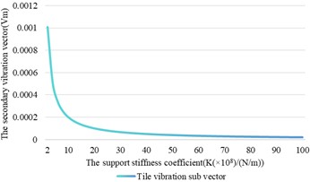
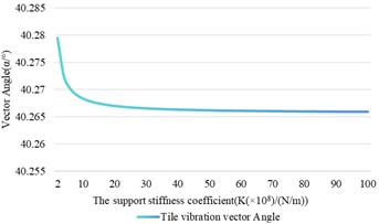
Based on the curve of the variation of the bearing vibration signal with the change of support stiffness, it can be seen that the trend of the bearing vibration signal is similar to that of the shaft vibration signal. Specifically, although the vector angle of the bearing vibration signal also decreases with the increase of the support stiffness, its descent speed is faster than that of the shaft vibration signal, indicating that the influence of the support stiffness on the vector angle of bearing vibration is more significant in the process of vibration transmission. Further comparison between shaft vibration and bearing vibration signals reveals that the main and secondary vibration vectors of bearing vibration signals are more significantly affected by changes in support stiffness than shaft vibration signals. For example, when the support stiffness is 2.0×10⁸ N/m, the values of the main and secondary vibration vectors of the shaft vibration signal are 0.0559 and 0.0190, respectively, while the values of the main and secondary vibration vectors of the bearing vibration signal are even smaller. When the support stiffness increases by 50 times to 1.0×10¹⁰ N/m, both the main and secondary vibration vectors of the shaft and tile vibration signals increase, but the amplification of the bearing vibration signal is significantly greater than that of the shaft vibration signal.
Besides, it can be seen that as the support stiffness increases, the amplitude of the variation of the bearing vibration signal is more sensitive than that of the shaft vibration signal, especially in terms of the vibration vector angle and magnitude. This difference reflects the important role of support stiffness in vibration transmission and system dynamic response, as well as the amplification effect of bearing vibration signals relative to shaft vibration, and this characteristic could be applied in monitoring support loosening fault effectively in engineering application, which means that it should be paid more attention to bearing vibration signal when support loosening fault arises.
Fig. 8The influence of support stiffness changes on shaft vibration and bearing vibration
a) Shaft vibration main vibration vector
b) Bearing vibration main vibration vector
c) Shaft vibration secondary vibration vector
d) Bearing vibration secondary vibration vector
e) Shaft vibration vector angle
f) Bearing vibration vector angle
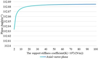
g) Shaft vibration vector phase
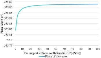
h) Bearing vibration vector phase
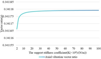
i) Shaft vibration vector ratio
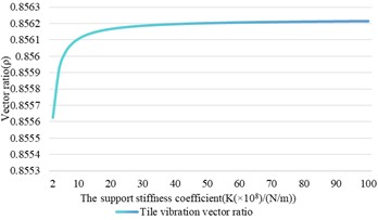
j) Bearing vibration vector ratio
4.4. The influence of changes in support damping on the shaft vibration and bearing vibration
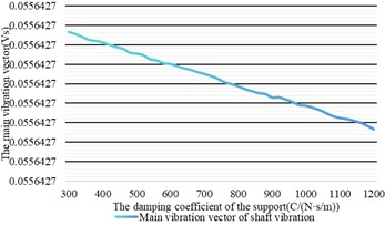
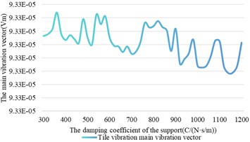
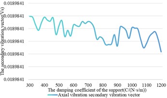
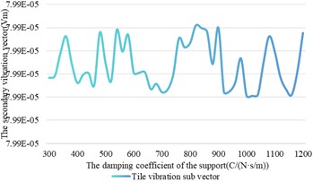
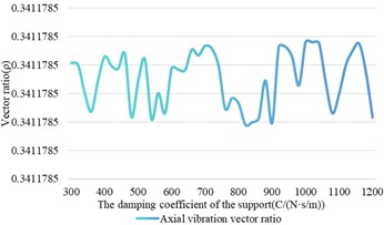
The stiffness coefficient of the support is equal in the x and y directions, both being 2.5×10⁹ N/m. Meanwhile, the damping coefficient Cx=Cy of the support varies between 300 N·s/m and 1200 N·s/m. Under these conditions, simulation experiments were conducted to investigate the influence of changes in support damping on the shaft vibration and bearing vibration.
From Fig. 9, we can observe that as the damping coefficient of the support changes, the main vector and vector phase of the shaft vibration signal show a decreasing trend, but the change is small and can be understood as maintaining stability. Similarly, the vector phase of the bearing vibration signal remains unchanged. However, as for the secondary vibration vector and vibration vector angle of the shaft vibration signal, as well as the main vibration vector, secondary vibration vector, vibration vector ratio, and vibration vector angle of the bearing vibration signal, although the change amplitude is not large, these parameters show certain fluctuations with the increase of the support damping coefficient. In addition, the vector ratio of the bearing vibration is greater than that of the shaft vibration, which means that the trajectory of the bearing vibration signal is closer to a circle than that of the shaft vibration signal. This indicates that the influence of support damping on bearing vibration is more significant than on shaft vibration. At the same time, the vibration vector ratio and vector angle of the shaft vibration signal are more susceptible to changes in support damping compared to bearing vibration signal, exhibiting small-scale fluctuations. However, from the overall trend, both shaft vibration and bearing vibration are relatively less affected by the changes in support damping.
Fig. 9The influence of damping changes on shaft vibration and bearing vibration
a) Shaft vibration main vibration vector
b) Bearing vibration main vibration vector
c) Shaft vibration secondary vibration vector
d) Bearing vibration secondary vibration vector
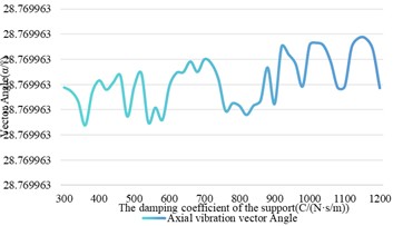
e) Shaft vibration vector angle
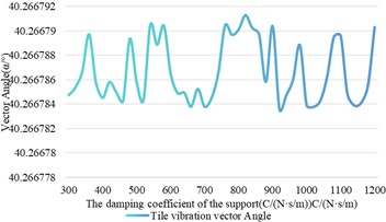
f) Bearing vibration vector angle
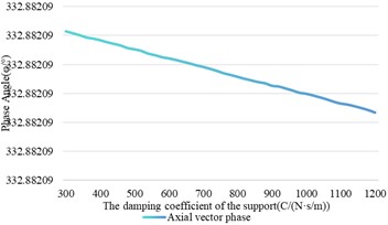
g) Shaft vibration vector phase
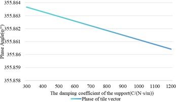
h) Bearing vibration vector phase
i) Shaft vibration vector ratio

j) Bearing vibration vector ratio
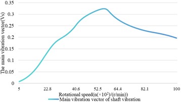
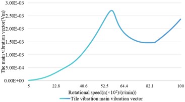
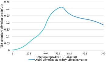
4.5. The influence of speed changes on the shaft vibration and bearing vibration
The rotational speed plays an important role in both the dynamic characteristics of the rotor bearing system and the efficiency of the rotor system. Therefore, under the condition of keeping the other parameters unchanged, the impact of speed changes on shaft vibration is analyzed using the established model, and the speed varies between 5×10² r/min and 1×10⁴ r/min.
Based on Fig. 10, it is shown that at a rotational speed of 5.5×10³ r/min corresponding to the natural frequency of the system, both the main and secondary vibration vectors of shaft and bearing vibrations reach their peak values. At different speeds, the secondary vibration vectors of them are positive, indicating that both the bearing vibration and shaft vibration can accurately indicate that the precession direction of the rotor is positive. However, when the speed exceeds 5.5×10³ r/min, which is beyond the natural frequency of the system, the main and secondary vibration vectors of shaft vibration decrease with the increase of speed, indicating the occurrence of automatic centering phenomenon. For bearing vibration, the main and secondary vibration vectors reach their minimum values at 8.3×10³ r/min and increase with the increase of rotational speed. This indicates that in a rigid rotor system, both the main and secondary vibration vectors of the bearing vibration can effectively reflect the basic vortex information of the rotor. In flexible rotor systems, the bearing vibration does not always decrease with the decrease of shaft vibration, but increases after decreasing to a certain extent.
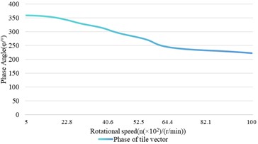
Based on Fig. 10, it can also be seen that the vector angles of the shaft vibration signal and the bearing vibration signal reach their maximum and minimum values at 3.1×10³ r/min and 5.5×10³ r/min, respectively. Especially between 8.5×10³ r/min and 8.7×10³ r/min, the vibration vector angle of the shaft vibration changed nearly 180°. The vector angle of the bearing vibration also underwent a similar change between 7.7×10³ r/min and 7.8×10³ r/min, and then tended to be stable. This indicates that when the rotational speed matches the natural frequency of a component in the system, there will be significant changes in the vector angles of the shaft and bearing vibrations, reaching maximum or minimum values. For the vector angle, the trend of changes in shaft vibration and bearing vibration is similar at lower speeds. However, as the rotational speed increases, there are significant differences in the variation trends of the vibration vector angles of shaft vibration and bearing vibration, as well as the rotational speed at which they reach their maximum and minimum values.
Fig. 10The influence relationship of speed changes on shaft vibration and bearing vibration
a) Shaft vibration main vibration vector
b) Bearing vibration main vibration vector
c) Shaft vibration secondary vibration vector
d) Bearing vibration secondary vibration vector
e) Shaft vibration vector angle
f) Bearing vibration vector angle
g) Shaft vibration vector phase
h) Bearing vibration vector phase
i) Shaft vibration vector ratio
j) Bearing vibration vector ratio
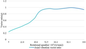
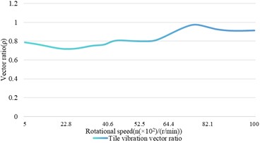
The vector phase of bearing vibration and shaft vibration decreases with the increase of rotational speed, but the fluctuation of shaft vibration is slightly greater than that of bearing vibration. The vibration vector ratio of shaft vibration fluctuates more than that of bearing vibration, indicating that the oil film stiffness and damping characteristics of the bearing will vary at different speeds, which will affect the vibration vector ratio of shaft vibration and bearing vibration. At certain speeds, the stiffness and damping of the bearing oil film may decrease, leading to increased fluctuations in shaft vibration.
4.6. The influence of variation of shaft stiffness coefficient on the shaft vibration and bearing vibration
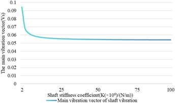
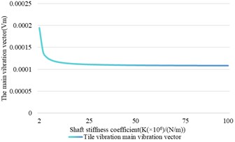
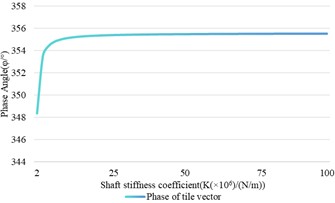
During the operation of the model system, various factors such as loads, unbalanced forces, and temperature may cause a certain degree of variation in the stiffness of the shaft. Therefore, we conducted a simulation analysis on the stiffness coefficient of the shaft between 2×10⁶ N/m and 1×10⁸ N/m. The corresponding results are presented in Fig. 11, on which the
Fig. 11The relationship between the variation of the stiffness coefficient and the shaft vibration and bearing vibration
a) Shaft vibration main vibration vector
b) Bearing vibration main vibration vector
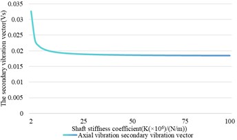
c) Shaft vibration secondary vibration vector
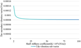
d) Bearing vibration secondary vibration vector
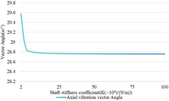
e) Shaft vibration vector angle
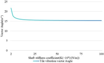
f) Bearing vibration vector angle
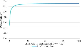
g) Shaft vibration vector phase
h) Bearing vibration vector phase
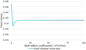
i) Shaft vibration vector ratio
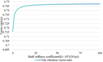
j) Bearing vibration vector ratio
When analyzing the shaft vibration signal based on Fig. 11, we noticed that the changes in the main and secondary vibration vectors exhibit similar patterns, both of which decrease with the increase of axial stiffness. Specifically, within the shaft stiffness ranging from 2×10⁶ N/m to 9×10⁶ N/m, both parameters undergo a rapid decline phase, with the main vibration vector decreasing from 0.0559 to 0.05562 and the secondary vibration vector decreasing from 0.019 to 0.01897. Afterward, their change trend became relatively flat. The vibration vector ratio reaches its lowest point when the stiffness reaches 4×10⁶ N/m, and then gradually increases with the further increase of stiffness. When the stiffness exceeds 7×10⁶ N/m, the vibration vector ratio remains constant. This indicates that once the stiffness of the shaft exceeds a certain threshold, the changes in the main and secondary vibration vectors will tend to be consistent, indicating that the trajectory shape of the rotor tends to be stable. The variation trend of the vector angle is consistent with the variation trend of the main and secondary vectors.
As for the bearing vibration signal, we observed that the main and secondary vibration vectors tend to be stable after the axial stiffness exceeds 5×10⁶ N/m. In addition, the variation amplitude of the secondary vibration vector is smaller than that of the main vibration vector, indicating that the main vibration vector is more sensitive to the stiffness of the shaft. As the stiffness increases, the vibration vector ratio shows an upward trend. The variation trend of the vector angle is consistent with the variation trend of the main and secondary vectors.
Furthermore, it can be seen that the trend of vector phase change is similar between them. Although the main and secondary vibration vectors of the bearing vibration and the shaft vibration show similar trends with the increase of shaft stiffness, there is a significant difference in their change speed. Specifically, as the stiffness of the shaft increases, the aspect ratio of the bearing vibration signal continues to rise, while the aspect ratio of the shaft vibration signal first sharply decreases after reaching a minimum value, then increases with the continued increase of stiffness, and finally stabilizes. In addition, the vector ratio of the bearing vibration signal is always greater than that of the shaft vibration signal, which means that the velocity trajectory synthesized by the bearing vibration signal is closer to a circle, while the trajectory of the shaft vibration signal is relatively elliptical. The vector angle reflects the direction of force acting on the rotor. With the stiffness of the shaft increasing, the difference in vector angle between shaft vibration and bearing vibration signals gradually stabilizes. This indicates that at higher shaft stiffness, the two signals can more consistently indicate the force direction of the rotor.
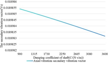
4.7. The influence of shaft damping changes on shaft vibration and bearing vibration
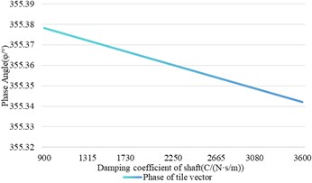
We conducted a series of simulation experiments on the established dynamic model when the damping coefficient of the shaft varied from 900 N·s/m to 3600 N·s/m. Through these experiments, we can evaluate the impact of changes in shaft damping on the dynamic characteristics of the system.
Fig. 12The influence of shaft damping change on shaft vibration and bearing vibration
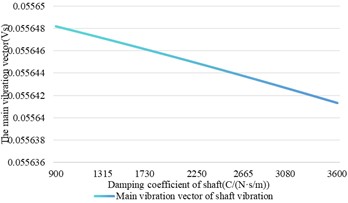
a) Shaft vibration main vibration vector
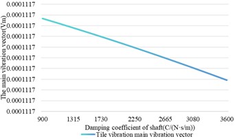
b) Bearing vibration main vibration vector
c) Shaft vibration secondary vibration vector
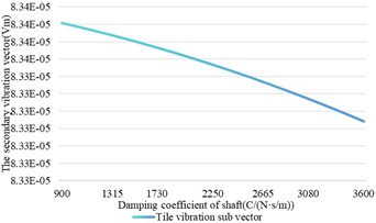
d) Bearing vibration secondary vibration vector
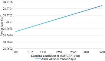
e) Shaft vibration vector angle
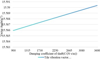
f) Bearing vibration vector angle
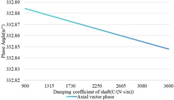
g) Shaft vibration vector phase
h) Bearing vibration vector phase
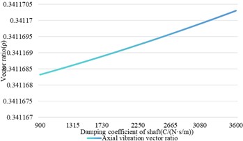
i) Shaft vibration vector ratio
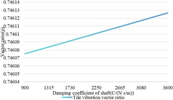
j) Bearing vibration vector ratio
From the axial vibration signal diagram as shown in Fig. 12, it can be seen that the changes in the main vector, secondary vector, and vector phases are positively correlated with the increase of the axial damping coefficient. That is, as the damping coefficient increases, the values of these parameters gradually decrease, and this trend of change is roughly linear. This phenomenon is mainly due to the proportional relationship between damping force and angular velocity, and the damping torque is closely related to the system's moment of inertia, damping coefficient, and angular velocity. As the damping coefficient increases, the damping torque also increases, leading to a decrease in the angular velocity of the rotating system. As a result, the amplitudes of the main and secondary vibration vectors decrease, and the trend of change is approximately linear. At the same time, the vector ratio and vector angle increase with the increase of the damping coefficient, which may be closely related to the influence of damping on the energy dissipation of the vibration system. The damping ratio is a key parameter for measuring the damping level of a system, which is related to the amplitude attenuation rate of the system’s free vibration. The increase in damping ratio means that the attenuation speed of system vibration accelerates, which may be the reason for the increase of vibration vector ratio and vibration vector angle, as these parameters are closely related to the vibration energy and vibration mode of the system. In short, as the damping coefficient of the shaft increases, the vibration characteristics of the system are significantly affected, manifested as a decrease in amplitude and a change in vibration mode.
From the bearing vibration signal diagram as shown in Fig. 12, it can be seen that the changing trends of the main vibration vector, secondary vibration vector, vibration vector angle, vector phase, and vibration vector ratio are similar to those of the axial vibration signal. This similarity arises from the fact that both bearing vibration and shaft vibration are caused by shaft vibration, where shaft vibration represents the radial vibration of the shaft and bearing vibration represents the vibration of the bearing seat. Because the vibration of the shaft is transmitted to the bearing seat, there is a correlation between the shaft vibration and the bearing vibration in terms of amplitude, phase, and frequency. As the damping coefficient of the shaft increases, the dissipation rate of system vibration energy accelerates, resulting in a decrease in the amplitude of the main and secondary vibration vectors. At the same time, the vector ratio and vector angle may increase due to changes in vibration modes. These changing trends reveal the influence of damping on the vibration characteristics of rotating machinery, which is of great significance for fault diagnosis and predictive maintenance.
By comparing the shaft vibration and bearing vibration signal diagrams, we noticed that there are significant similarities between them in terms of the variation trends of the main vector, secondary vector, vector ratio, vector phase, and vector angle. However, the range of values for the bearing vibration signal is relatively small, indicating that the influence of shaft damping on shaft vibration and bearing vibration is limited. In short, although the trend of changes in shaft vibration and bearing vibration signals is similar, the amplitude of changes in bearing vibration signals is relatively smaller, indicating that damping does not have a significant impact on these two types of vibrations.
4.8. The influence of changes in bearing quality on shaft vibration and bearing vibration
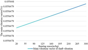
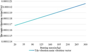
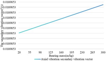
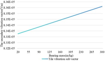
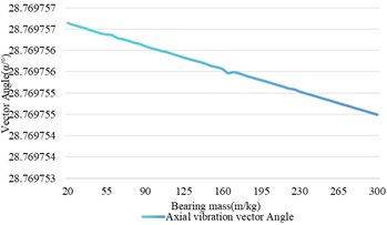
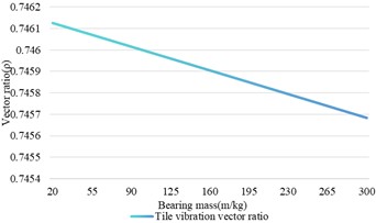
The selection of bearings has a significant impact on vibration characteristics. In the simulation analysis, a detailed study was conducted on the established model when the mass of the bearing varied between 20 kg and 300 kg.
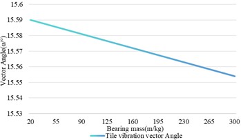
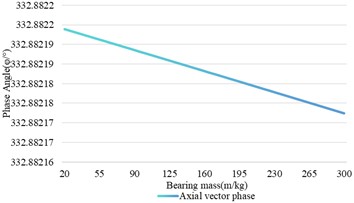
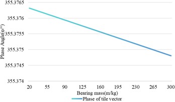
By analyzing the relationship between the shaft vibration signals and the changes in bearing mass based on Fig. 13, we can observe that both the main and secondary vibration vectors increase with the increase of bearing mass, but this growth is shown as basically stable in the graph, indicating that the growth amplitude is not significant. Meanwhile, the vector angle, vector phase, and vector ratio decrease with increasing of bearing mass, but remain relatively stable, indicating that the changes in these parameters are not significant. Overall, the impact of changes in bearing quality on shaft vibration signals is relatively limited. This means that within this mass range, the shaft vibration characteristics have not undergone significant changes due to an increase in bearing mass.
Fig. 13Relationship between changes in bearing mass and shaft vibration and bearing vibration
a) Shaft vibration main vibration vector
b) Bearing vibration main vibration vector
c) Shaft vibration secondary vibration vector
d) Bearing vibration secondary vibration vector
e) Shaft vibration vector angle
f) Bearing vibration vector angle
g) Shaft vibration vector phase
h) Bearing vibration vector phase
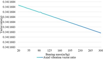
i) Shaft vibration vector ratio
j) Bearing vibration vector ratio
By observing the curve of the bearing vibration signal changing with the bearing mass as shown in Fig. 13, we can find that the trend of the bearing vibration signal is similar to that of the shaft vibration signal, and it is approximately linearly related. This similarity is due to the reason that both of them are controlled by the vibration characteristics of the shaft. However, the amplitude of changes in the secondary vibration vector, vector angle, vector phase, and vector ratio of the bearing vibration signal is more significant than that of the shaft vibration signal. This is because the vibration of the shaft is transmitted to the bearing seat through the bearing, causing bearing vibration, which not only reflects the vibration characteristics of the shaft but also may be affected by the stiffness and mass distribution of the bearing seat. Therefore, the variation of the bearing vibration signal amplifies the variation of the shaft vibration signal to a certain extent, making the bearing vibration more sensitive to changes in bearing quality.
By comparing the signals of shaft vibration and bearing vibration, it can be observed that the trends of their changes are similar. Moreover, the impact of changes in bearing quality on bearing vibration is significantly greater than its impact on shaft vibration.
4.9. Experimental verification
To verify the accuracy of the simulation results, we built a rotor test bench as shown in Fig. 14. The rotor test bench is driven by an asynchronous motor, and the rotor system is supported by two sliding bearings with the same structure. A disk is arranged in the middle of the shaft, and the natural frequency of the rotor is about 2600 r/min, while the natural frequency of the bearing system is about 3600 r/min. Two eddy current sensors of the same model are arranged at the shaft neck of the rotor test bench, and two speed sensors of the same model are arranged at the bearing seat. The relative displacement signal at the shaft neck and the absolute velocity signal at the bearing seat are obtained through acquisition instruments.
Fig. 14Rotor test bench
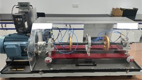
a) Physical image of the test bench
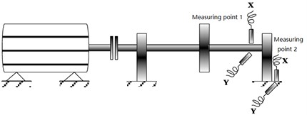
b) Schematic diagram of rotor test bench
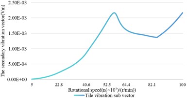
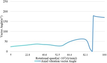
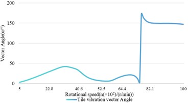
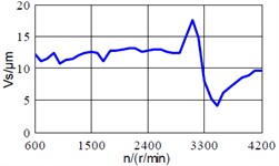
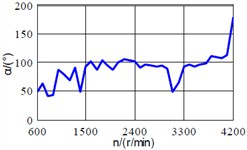
Conduct experimental research on the relationship between shaft vibration and bearing vibration of the rotor system when the speed varies between 600 r/min and 4200 r/min. Among them, 32 points are collected per cycle for a total of 32 rotations. From the full vector spectrum of the shaft vibration signal and the bearing vibration signal in Fig. 15, it can be seen that below 2500 r/min, the main vibration vectors of the bearing vibration and the shaft vibration both increase with the increase of speed, and at 2500 r/min, the main vibration vector of the shaft vibration reaches a maximum value of 35.21 μm, and the main vibration vector of the bearing vibration reaches a maximum value of 0.16 mm/s. When the speed is above 2500 r/min, the main vibration vector of the shaft vibration decreases with the increase of the speed, while the main vibration vector of the bearing vibration reaches its minimum value at 3100 r/min and increases with the increase of the speed. It reaches its maximum value of 0.447 mm/s at the natural frequency of 3600 r/min of the bearing and then decreases again. Under the condition of a rigid rotor, the main vibration vectors of the bearing vibration signal and the shaft vibration signal show similar trends with respect to speed, while under the condition of a flexible rotor, the trends of the two are significantly different. The secondary vibration vectors of the shaft vibration signal and the bearing vibration signal correctly reflect that the rotor precession direction is positive precession, which is consistent with the simulation analysis results. The axial vibration vector angle exhibits a significant abrupt change with the variation of rotational speed, while the variation of the bearing vibration vector angle is relatively stable, which is also consistent with the simulation analysis results.
Fig. 15Experimental result
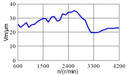
a) The main vibration vector’ trend of shaft vibration with varying of rotating speed
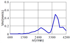
b) The main vibration vector’ trend of bearing vibration with varying of rotating speed
c) The secondary vibration vector’ trend of shaft vibration with varying of rotating speed
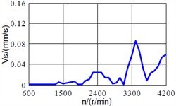
d) The secondary vibration vector’ trend of bearing vibration with varying of rotating speed
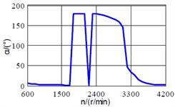
e) The vibration vector angle of shaft vibration with varying of rotating speed
f) The vibration vector angle of bearing vibration with varying of rotating speed
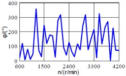
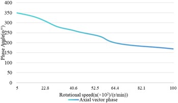
g) The vibration vector phase of shaft vibration with varying of rotating speed
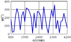
h) The vibration vector phase of shaft vibration with varying of rotating speed
5. Conclusions
This article constructs a dynamic model under unbalanced conditions by integrating the characteristics of shaft vibration and bearing vibration, and uses full vector spectrum technology to perform dual-channel source information fusion analysis on shaft vibration and bearing vibration signals under different system parameters. Finally, the simulation results were verified by building a test bench, and the following conclusions were drawn:
1) The main and secondary vibration vectors of the shaft vibration signal and the bearing vibration signal are linearly related to the eccentricity. However, the rate of change of the vibration vector of the shaft vibration signal is faster than that of the bearing vibration signal. The quality of the disc, the quality of the bearings, and the damping of the shaft and support have a relatively small impact on the shaft vibration and bearing vibration.
2) As the support stiffness increases, the main and secondary vibration vectors, as well as the vibration vector angle, the shaft and bearing vibration signals decrease, and this change exhibits significant nonlinear characteristics. Compared to shaft vibration, bearing vibration is more sensitive to changes in support stiffness, especially when the vector angle of bearing vibration signals exhibits a certain degree of uncertainty.
3) Under the condition of a rigid rotor, the main vibration vectors of the shaft vibration and bearing vibration signals will increase with the increase of rotational speed. Under flexible rotor conditions, the main vibration vector of the shaft vibration signal decreases with increasing speed, while the main vibration vector of the bearing vibration signal shows a trend of first decreasing and then increasing. There is a significant difference between them. Therefore, when conducting on-site dynamic balancing of flexible rotor systems, it is necessary to fully consider the complex relationship between bearing vibration and shaft vibration.
4) The experimental results are consistent with the simulation results, which proves the effectiveness and reliability of the adopted method.
Although the proposed method has achieved satisfactory results, there is still a significant gap between the constructed dynamic model and the model in practical applications, and the model is influenced by various external factors. Therefore, in future research, we will focus on making the model more in line with the needs of the actual working environment. Besides, the following two issues will be also addressed in future research:
1) Due to the many types of faults that occur in the rotor-bearing-foundation system, such as rotor misalignment, oil film oscillation, rotor cracks, etc., this article only analyzes and studies common unbalance faults, which is obviously insufficient for the study of the relationship between shaft vibration and bearing vibration. Therefore, further in-depth research is needed on the relationship between shaft vibration and bearing vibration of the rotor-bearing-foundation system under other types of faults, as well as the similarities and differences in the fault information expressed.
2) Although the relationship between shaft vibration and bearing vibration under unbalanced conditions has been analyzed using full vector spectrum technology, it can be seen from the analysis that there are significant similarities in the main and secondary vibration vectors as well as the vibration vector ratio between the shaft vibration signal and bearing vibration signal. Therefore, in conventional state monitoring and fault analysis, full vector spectrum technology can be applied to contact detection to improve fault identification capability. However, when conducting precise fault diagnosis, there are significant difficulties in determining the relationship between the shaft vibration vector angle and the bearing vibration vector angle, and further research is still needed.
References
-
Y. Chen, X. Liu, M. Rao, Y. Qin, Z. Wang, and Y. Ji, “Explicit speed-integrated LSTM network for non-stationary gearbox vibration representation and fault detection under varying speed conditions,” Reliability Engineering and System Safety, Vol. 254, p. 110596, Feb. 2025, https://doi.org/10.1016/j.ress.2024.110596
-
Y. Ji, Y. Huang, J. Zeng, L. Ren, and Y. Chen, “A physical-data-driven combined strategy for load identification of tire type rail transit vehicle,” Reliability Engineering and System Safety, Vol. 253, p. 110493, Jan. 2025, https://doi.org/10.1016/j.ress.2024.110493
-
L. Yang, Z. Mao, X. Chen, R. Yan, J. Xie, and H. Hu, “Dynamic coupling vibration of rotating shaft-disc-blade system – Modeling, mechanism analysis and numerical study,” Mechanism and Machine Theory, Vol. 167, p. 104542, Jan. 2022, https://doi.org/10.1016/j.mechmachtheory.2021.104542
-
F. Kuang et al., “Computer-vision-based research on friction vibration and coupling of frictional and torsional vibrations in water-lubricated bearing-shaft system,” Tribology International, Vol. 150, p. 106336, Oct. 2020, https://doi.org/10.1016/j.triboint.2020.106336
-
Z. Chen, J. Wang, R. Li, and Y. Liu, “A novel 4-DOF marine stern bearing support model considering discrete distribution effects,” Ocean Engineering, Vol. 312, p. 119072, Nov. 2024, https://doi.org/10.1016/j.oceaneng.2024.119072
-
L.-H. Yang, Y. Sun, Z.-B. Yang, Z. Mao, and X.-F. Chen, “Coupling vibration mechanism of rotating shaft-disc-blade system with blade crack-A systematical investigation on the effect of crack, condition, and structure parameters,” Thin-Walled Structures, Vol. 205, p. 112398, Dec. 2024, https://doi.org/10.1016/j.tws.2024.112398
-
G. Chandrashekar, W. Raj, C. Godwin, and P. S. Paul, “Study on the influence of shaft material on vibration in rotating machinery,” Materials Today: Proceedings, Vol. 5, No. 5, pp. 12071–12076, Jan. 2018, https://doi.org/10.1016/j.matpr.2018.02.182
-
Y. Wu, W. Zhang, S. Yi, X. Wang, Y. Qin, and S. Peng, “Theoretical and experimental study of flexible structure tilting pad bearings considering deformation,” Lubricants, Vol. 12, No. 8, p. 284, Aug. 2024, https://doi.org/10.3390/lubricants12080284
-
Y. Yang, C.-D. Che, and W.-Y. Tang, “Shafting coupled vibration research based on wave approach,” Journal of Shanghai Jiaotong University (Science), Vol. 19, No. 3, pp. 325–336, Jun. 2014, https://doi.org/10.1007/s12204-014-1506-6
-
Y. Xuan, G. Zhu, X. Luo, Y. Wang, and L. Wang, “Experimental study on the stability of mixed-flow pump during segmented start-up process,” Arabian Journal for Science and Engineering, pp. 1–13, Jul. 2024, https://doi.org/10.1007/s13369-024-09350-6
-
J. G. Yang and Y. W. Tian, “In-depth study of the proportional relationship between shaft vibration and tile vibration of large-scale rotating machinery,” in Proceedings of the Fifth National Seminar on Equipment Optimization and Maintenance Technology of Power Generation Enterprises, National Engineering Research Center for Thermal Power Unit Vibration, Southeast University, Vol. 6, 2009.
-
T. K. Ma and F. F. Zhang, “Analysis and treatment of 300Mvar condenser tile vibration jumping machine,” Large Electric Machine and Hydraulic Turbine, pp. 51–56, 2024.
-
D. L. Du, “For the first time, the back pressure generator set started the analysis and elimination measures of excessive vibration of tile vibration,” China Plant Engineering, pp. 153–154, 2021.
-
G. C. Zhu, “Analysis of the reasons for the large load shaft vibration of the steam induced draft fan of thermal power generating unit,” Science and Technology and Innovation, Vol. 7, pp. 105–107, 2024, https://doi.org/10.15913/j.cnki.kjycx.2024.07.028
-
Q. Zhou, “Analysis and treatment of axial vibration fault of air compressor in air separation equipment,” Metallurgical Power, Vol. 1, pp. 17–20, 2024, https://doi.org/10.13589/j.cnki.yjdl.2024.01.012
-
J. Y. Xu, Q. S. Pan, and Z. Q. Li, “Analysis and treatment of anomalies in the axial vibration measurement points of a UHV condenser Bently3500 system,” Electric Switchgear, Vol. 61, pp. 96–100, 2023.
-
Y. H. Wei, Q. Shu, and Y. F. Liu, “Shaft vibration/watt vibration correlation analysis when the vibration protection logic of the turbine generator set is set,” Turbine Technology, Vol. 57, pp. 451–453, 2015.
-
W. Zhu, C. Y. Zhou, and F. Y. Guan, “Shaft vibration analysis and treatment of steam turbine generator,” Energy Conservation Technology, Vol. 41, pp. 244–247, 2023.
-
L. J. Jia, J. Wang, and X. B. Zhang, “Comprehensive application of shaft vibration and watt vibration information to judge the working state of the sliding bearing,” Journal of Chinese Society of Power Engineering, Vol. 30, pp. 844–848, 2010.
-
Z. N. Ma et al., “Analysis and treatment of abnormal steam turbine watt temperature and shaft vibration,” Thermal Turbine, Vol. 52, pp. 226–229, 2023, https://doi.org/10.13707/j.cnki.31-1922/th.2023.03.013
-
L. B. Li and K. B. Zhang, “Analysis of abnormal vibration of a steam turbine under deep regulation condition,” Turbine Technology, Vol. 65, pp. 74–76, 2023.
-
Y. X. Tian et al., “Denoising research of shaft vibration signal based on CEEMDAN and mathematical morphology operator,” Chinese Journal of Hydrodynamics, pp. 1–8, 2024, https://doi.org/10.16076/j.cnki.cjhd.2024.06.016
-
Y. Tao, G. Li, and Y. Wang, “Numerical investigation on tooth surface waviness in continuous generating grinding of electric vehicle gears considering the main shaft vibration and grinding worm wear,” Precision Engineering, Vol. 91, pp. 242–254, Dec. 2024, https://doi.org/10.1016/j.precisioneng.2024.09.015
About this article

This work was supported in part by the Key science and technology research project of the Henan province (Grant No. 252102221044), in part by the Youth Science and Technology Fund Project of China Minmetals Corporation (Grant No. 2024QNJJB15), in part by the Major R&D Project of the “181 Program” by China Metallurgical Group Corporation (Grant No. 2022ZY181A07), and in part by the Special Project Fund for Doctoral Innovation by China Fifth Metallurgical Group Co., Ltd (Grant No. WY2023C007).
The datasets generated during and/or analyzed during the current study are available from the corresponding author on reasonable request.
Hongchao Wang: conceptualization, funding acquisition, investigation, methodology, supervision, visualization, writing-review and editing. Shijin Chen: data curation, formal analysis, project administration, resources, software, validation, writing-original draft preparation.
The authors declare that they have no conflict of interest.
