Abstract
In current research, the anchoring performance of prestressed Carbon Fiber Reinforced Polymer (CFRP) plate anchors is primarily acquired through experimental methods, which makes it difficult to capture the internal deformation and stress distribution of the anchor. In this paper, a model of a grouted cylindrical wedge anchor for prestressed CFRP plates is established using the finite element analysis software ABAQUS. The simulation replicates the processes of anchor relaxation at the release end and the second tensioning at the tensioning end, using a geometrically nonlinear static general analysis step. This approach yields the shear stress distribution at the interface between the internal adhesive and the carbon fiber plate, as well as the deformation and normal stress distribution within the carbon fiber plate. The analysis results provide technical support and theoretical backing for experiments and research on prestressed CFRP plate grouted cylindrical wedge anchors.
1. Introduction
The prestressed CFRP plate anchor is a common reinforcement tool. It utilizes a tensioning device to stretch the CFRP sheet to a certain strength and then fixes it to the tensile surface of the reinforced concrete structure, forming a prestressed system. Compared to the deficiency of low CFRP strength utilization in traditional adhesive bonding methods [1], prestressed CFRP enhances the utilization rate of the CFRP material, significantly improving the structural yield load and ultimate bearing capacity [2-8].
Many forms of CFRP anchors have emerged both domestically and internationally [9-12], however, all of these anchors possess deficiencies and areas for improvement. Y. Tang [13] successfully optimized and improved the anchor device by incorporating a carbon fiber plate between the chuck and the clamping piece, and successfully developed a grouted cylindrical wedge anchor system. The prestressed CFRP grouted cylindrical wedge anchor system comprises five components: a fixed plate, the anchor itself, a gasket, an adhesive, and a carbon fiber plate, as illustrated specifically in Fig. 1.
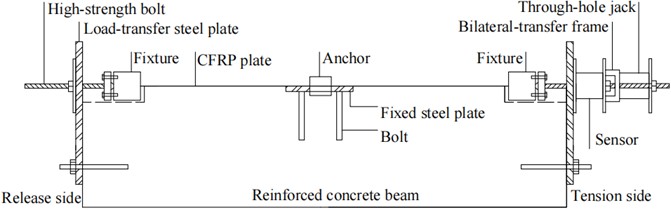
The research on the anchoring performance of prestressed CFRP grouted cylindrical wedge anchor system primarily relies on experimental approaches, with the experimental setup depicted in Fig. 2. During the experiment, a prestress of 110 KN is first applied at the tensioning end. Then, an adhesive is injected into the interior of the anchor. Once the adhesive reaches the desired strength, tension is released at the release end, followed by a second tensioning at the tensioning end. However, experimental research on anchors is often constrained by various factors: Firstly, it is difficult to find a reliable method to measure the internal deformation and stress distribution within the anchor, often relying solely on the analysis of experimental phenomena to infer the internal stress state, which lacks robust data support. Secondly, experimental research is often costly and time-consuming. With the rapid development of computer technology, numerous high-performance finite element analysis software has been developed domestically and internationally, making it possible to analyze anchor mechanisms and optimize anchors through numerical analysis methods. Utilizing finite element software to analyze anchors not only provides faster results and reduces costs but also enables the obtaining of internal stress and strain states within the anchor, providing reliable data support for anchor research. In this paper, a grouted cylindrical wedge anchor was established through the finite element analysis software ABAQUS, and the stress states of the carbon fiber plate and adhesive within the anchor were analyzed.
Fig. 1The schematic diagram inside anchorage
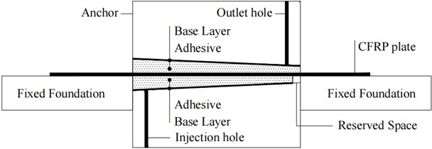
Fig. 2The device of anchorage tests
2. Construct of a simulation model
2.1. Model simplification
This article primarily analyzes the stress states of adhesive and carbon fiber plates. The fixed plate, which is used to secure the anchor cup, is not the primary focus of this study and is thus simplified as a boundary constraint condition introduced into the model. The shim serves as an isolating layer to prevent direct contact between the adhesive and the anchor cup. During testing, the shim moves along with the adhesive relative to the anchor cup without generating movement relative to the adhesive, thereby preventing cracks in the adhesive due to significant friction with the inner wall of the anchor. The role of the shim will be omitted in the finite element analysis. Therefore, this article mainly considers the interactions among the anchor cup, adhesive, and carbon fiber plates within the grouted cylindrical wedge anchor system.
The geometry of the grouted cylindrical wedge anchor system is symmetrical about the central plane of the carbon fiber plate. In the actual stress state, the anchor cup remains stationary. If a semi-model symmetrical about the central plane that bisects the thickness of the carbon fiber plate is analyzed, it will not significantly affect the stress states of the adhesive and the carbon fiber plate. However, there will be larger errors in the stress state of the anchor cup. Since the stress state of the anchor cup is not the primary focus of this article, it can be considered feasible to analyze using a semi-model symmetrical about the central plane that bisects the thickness of the carbon fiber plate.
The simplified model comprises two interfaces: the first interface is between the adhesive and the carbon fiber plate, and the second interface is the contact surface between the adhesive and the anchor cup. The adhesive serves as a bridge: the force in the carbon fiber plate is first transmitted to the epoxy resin adhesive through the shear force at the first interface, and then the epoxy resin adhesive transfers the force to the anchor through the compressive force and friction at the second interface, completing the anchoring action.
2.2. Material properties of each component
The material properties of steel and CFRP plates are selected according to the current relevant national standards and specifications, as shown in Table 1. It should be noted that existing literature does not directly provide information on the Poisson’s ratio of CFRP plates. However, related data indicates that the Poisson’s ratio of rubber is 0.47, and that of glass ranges from 0.13 to 0.3. Since CFRP plates belong to polymer materials, their Poisson’s ratio falls within this range. In this analysis, a value of 0.25 is adopted for the Poisson's ratio of CFRP plates.
Table 1Properties of steel and CFRP
Component | Elastic modulus (MPa) | Poisson’s ratio |
CFRP plate | 1.6×10⁵ | 0.25 |
Adhesive | 2500 | 0.25 |
Anchor cup (steel) | 2.06×10⁵ | 0.30 |
2.3. Setup of analysis steps and definition of boundary conditions
During the experiment, a prestress of 110 KN is first applied at the tensioning end. Then, epoxy resin adhesive is injected into the interior of the anchor. Once the epoxy resin adhesive reaches the expected strength, tension is released at the release end. Finally, a second tensioning is conducted at the tensioning end.
In this paper, an ABAQUS model consisting of five analysis steps (including an initial step) is designed to precisely simulate the critical stages in the tensile reinforcement process of carbon fiber plates. Besides the initial step, four nonlinear static analysis steps are set up: pre-tension, contact, tension release, and re-tension, all of which take into account geometric nonlinear effects.
The pre-tension analysis step is used to simulate the initial tensioning of the carbon fiber plate without the constraint of the adhesive. Through the use of the “birth and death” element technique, the role of the adhesive and anchor cup is temporarily removed, and only the carbon fiber plate is activated. The carbon fiber plate is set with a thickness of 1.4 mm and a width of 50 mm. The constraint applied to the carbon fiber plate is a constraint in the X-direction (i.e., the direction perpendicular to the central symmetric plane that bisects the plate thickness) on the central symmetric plane that bisects the plate thickness. A tensile stress of 1600 MPa is applied at both ends to simulate the effect of applying a prestress of 110 KN at the tensioning end.
The contact analysis step is used to establish a stable contact relationship between the components of the anchor system. The adhesive and anchor cup elements that were suppressed in the pre-tension analysis step are activated. A fixed constraint is applied to the tensioning end of the CFRP plate. Then, a displacement of 0.001 mm in the positive Z-direction (i.e., the opposite direction of the tensile force applied at the tensioning end of the carbon fiber plate) is given to the semicircular surface of the large notch end of the anchor cup. Additionally, constraints in all directions except the Z-direction are applied to two rectangular planes on the anchor cup that are flush with the central symmetric plane of the carbon fiber plate. The relevant constraints from the pre-tension analysis step are retained in this step.
The tension release analysis step is used to simulate the tension release behavior of the carbon fiber plate at the release end. The constraint conditions from both the pre-tension analysis step and the contact analysis step are retained. Simultaneously, a compressive stress of 1600 MPa is applied at the release end to simulate the tension release behavior.
The tensioning analysis step is used to simulate the second tensioning of the CFRP plate. The fixed constraint at the tensioning end of the CFRP plate from the contact analysis step is removed, while all other constraint conditions remain unchanged. A tensile stress of 800 MPa is then applied at the tensioning end to complete the simulation of the second tensioning.
2.4. Mesh segmentation
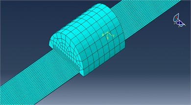
In the model, the CFRP plate and the adhesive are the primary focus, thus during mesh generation, the element sizes for both the CFRP plate and the adhesive need to be relatively small. On the other hand, the anchor cup is not the main focus of this model, so its elements can be relatively larger during mesh generation. The element sizes for both the CFRP plate and the adhesive are set to 2, with the element type being C3D8R, which stands for an 8-node reduced integration hexahedral element. The seed size for the anchor cup is set to 15, with the element type also being C3D8R. A schematic diagram of the mesh generation for the finite element model is shown in Fig. 3.
Fig. 3Mesh of the model
3. Simulation analysis and results discussion
3.1. Model simplification
The shear stress on the contact surface between the adhesive and the CFRP plate is of particular interest, with the shear stress within the X-Z plane being primarily significant. Therefore, the stress contour plot within the X-Z plane of the adhesive is presented here. The shear stress contour plot in the X-Z plane (perpendicular to the plane of the CFRP plate) of the adhesive after the completion of the tension release step and the tensioning step is illustrated in Fig. 4.
Fig. 4Stress contour plot of the adhesive in the X-Z plane
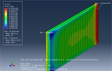
a) During tension release analysis step
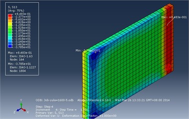
b) During tensioning analysis step
After the tension release analysis step, the maximum shear stress within the X-Z plane of the adhesive is –26.42 MPa, occurring at the corner where the release end contacts the CFRP plate. The minimum shear stress is 4.58 MPa, occurring at the end of the contact surface between the tensioning end and the CFRP plate. After the completion of the tensioning analysis step, the maximum shear stress within the adhesive is –37.85 MPa, also occurring at the corner where the release end contacts the CFRP plate. The minimum shear stress is 0.85 MPa, occurring at the end of the contact surface between the tensioning end and the CFRP plate. According to experimental research on the grouted cylindrical wedge anchor, the bonding shear strength of the adhesive can reach 45.00 MPa, which exceeds the maximum shear stress in the X-Z plane of the adhesive during both the tension release and tensioning analysis steps, as indicated by the analysis. Therefore, based on the analysis results, it can be concluded that there will be no slip between the adhesive and the CFRP plate.
The distributions of shear stress in the width direction at the ends of both the release end and the tensioning end of the adhesive, as well as along the middle length of the adhesive, after the completion of both the tension release analysis step and the tensioning analysis step, are illustrated in the Fig. 5.
After the tension release and tensioning of the CFRP plate, stress concentration of the shear stress in the X-Z plane of the adhesive is observed at both the release end and the tensioning end, with the concentration located at the center of the adhesive’s width.
After the tension release analysis step, within a distance of approximately 3.0 mm from the release end of the anchor cup, the shear stress in the X-Z plane of the adhesive layer decreases. From 3.0 mm to 23.8 mm distance from the release end, the shear stress increases in a pattern that first slows, then accelerates, and finally slows again, followed by a horizontal development. The shear stress then rises rapidly from 71.4 mm to the tensioning end of the anchor cup. After the tensioning analysis step, within a distance of approximately 3.0 mm from the release end, the shear stress in the X-Z plane of the adhesive layer decreases, and then increases rapidly before slowing down between approximately 3.0 mm and 20.8 mm from the release end, followed by a horizontal development. The shear stress then rises rapidly between approximately 65.6 mm and 74.4 mm from the release end, and decreases between approximately 74.4 mm and 80.4 mm. There is a noticeable concentration of shear stress at the ends of the adhesive layer, yet the absolute values of the shear stress at the ends are relatively small. The shear stress is uniformly distributed in most of the middle section. Therefore, the X-Z shear stress on the contact surface between the adhesive layer and the CFRP plate exhibits a relatively ideal uniform distribution. In addition, according to the reciprocal theorem of shear stress, the X-Z shear stress at the edges of the adhesive layer should be zero. Further refinement of the adhesive mesh can ensure that the calculation results meet this theoretical value.
Fig. 5Shear stress distribution diagram of the adhesive in the X-Z direction
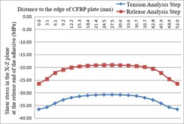
a) Along the width path at the release end of the adhesive
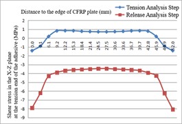
b) Along the width path at the tensioning end of the adhesive
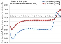
c) Along the length path of the adhesive
3.2. Results of CFRP plate calculations
The CFRP plate was tensioned to 1600 MPa during the preload analysis step, with uniform stress distribution and no stress concentration observed. During the contact analysis step, the stress and strain of the CFRP plate remained unchanged, consistent with those in the preload analysis step. Therefore, this subsection only presents the calculation results of the CFRP plate during the tension release analysis step and the tensioning analysis step.
After the completion of both the tension release analysis step and the tensioning analysis step, the maximum displacement of the CFRP plate occurred in the Z-direction, as shown in the displacement contour plot in Fig. 6.
After the tension release analysis step, the maximum displacement in the Z-direction within the CFRP plate was –1.70 mm, occurring near the middle edge, while the minimum displacement was –7.18 mm, occurring at the corner of the tensioning end. After the tensioning analysis step, the maximum displacement in the Z-direction within the CFRP plate was –4.45 mm, also occurring near the middle edge, and the minimum displacement was –15.31 mm, occurring at the tensioning corner.
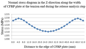
The stress distribution in the Z-direction, which corresponds to the lengthwise direction of the CFRP plate, is crucial for studying stress concentration in the CFRP plate. Below are presented the stress contour plots in the Z-direction of the CFRP plate after the tension release analysis step and the tensioning analysis step. Additionally, the normal stress distributions along the width direction at the release end and tensioning end, as well as along the length direction at the middle section, within the anchor cup area of the CFRP plate, are provided.
After the release and tensioning of the CFRP plate, stress concentration phenomena are observed in the Z-direction at both the release end and the tensioning end of the CFRP plate, located centrally across its width.
Upon completion of the tension release analysis step, the stress in the Z-direction of the CFRP plate shows a generally linear increase along its length. However, around 76.5 mm away from the release end of the anchor cup, the increase significantly slows down, indicating that the adhesive exerts little influence on the CFRP plate after it slides out of the anchor cup. Similarly, upon completion of the tensioning analysis step, the stress in the Z-direction of the CFRP plate also shows a generally linear increase along its length. But around 68.4 mm away from the release end of the anchor cup, the increase markedly slows down, suggesting that the adhesive ceases to have a significant impact on the CFRP plate once it exits the anchor cup.
Fig. 6Displacement contour plot of CFRP plate in Z-direction
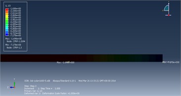
a) During tension release analysis step
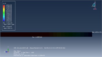
b) During tensioning analysis step
Fig. 7Stress contour plot of CFRP plate in Z-direction
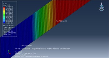
a) During tension release analysis step
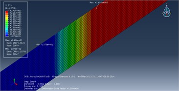
b) During tensioning analysis step
4. Conclusions
In this paper, we establish a finite element model for the grouted cylindrical wedge anchor designed for CFRP plates. By setting up analysis steps, we investigate the mechanical states within the anchor after tension release at the release end and after the second tensioning at the tensioning end. This includes the shear stress distribution of the adhesive in the X-Z plane, as well as the deformation and stress distribution in the Z-direction of the CFRP plate. The purpose of this research is to provide theoretical basis and technical support for the experimental study and optimization of the grouted cylindrical wedge anchor used in prestressed CFRP plates.
Fig. 8Stress distribution diagram of CFRP plate in Z-direction
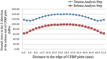
a) Along the width path at the release end within the anchor
b) Along the width path at the tensioning end within the anchor during the tension release analysis step
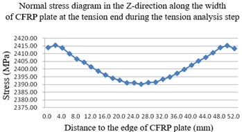
c) Along the width path at the tensioning end within the anchor during the tensioning analysis step
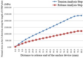
d) Along the length path inside the anchor
1) After both the tension release and the second tensioning processes, the shear stress experienced by the adhesive in the X-Z plane remains below 45 MPa, which is lower than the adhesive's bond shear strength. This indicates that there will be no relative slippage between the adhesive and the CFRP plate.
2) At the release end of the anchor, there is a concentration of X-Z shear stress at the interface between the adhesive and the CFRP plate. However, the maximum shear stress does not exceed the bond shear strength of the adhesive (45 MPa). In the middle region of the anchor, the shear stress distribution is uniform. At the tensioning end, the shear stress is relatively small, indicating an ideally uniform distribution overall.
3) The normal stress along the length direction in the edge region of the CFRP plate is greater than that in the middle region. This suggests that damage to the CFRP plate would likely initiate in the edge region before the middle region.
4) The normal stress along the length direction of the CFRP plate within the anchor increases linearly from the release end to the tensioning end, which represents an ideal distribution pattern. Additionally, the displacements of the CFRP plate are minimal after both the tension release and the second tensioning processes.
References
-
T. C. Triantafillou and N. Deskovic, “Innovative. Prestressing with FRP sheets: mechanics of short-term behavior,” Journal of Engineering Mechanics, Vol. 117, No. 1, pp. 1652–1672, 1991.
-
W. C. Xue and L. Zeng, “Overview of research on strengthening concrete beams with prestressed CFRP plates,” (in Chinese), Industrial Construction, Vol. 2006, No. 4, pp. 12–14, 2006.
-
G. Wu and Z. T. Lv, “Flexural design method for strengthening concrete structures with externally bonded CFRP,” (in Chinese), Building Structure, Vol. 2000, No. 7, pp. 7–10, 2000.
-
F. J. Chen and G. J. Teng, “Anchorage strength models for FRP and steel plates bonded to concrete,” (in Chinese), Journal of Structural Engineering, Vol. 127, No. 7, pp. 784–791, 2001.
-
X. T. Zeng, X. G. Wang, and Y. H. Ding, “Research on prestressing methods for strengthening concrete beams with bonded prestressed FRP sheets,” (in Chinese), Journal of Jiaozuo Institute of Technology, Vol. 21, No. 3, pp. 222–225, 2002.
-
X. Y. Guo, P. Y. Huang, and X. H. Zheng, “Stress analysis of RC beams strengthened with prestressed FRP,” (in Chinese), Journal of South China University of Technology (Natural Science Edition), Vol. 2005, No. 7, pp. 6–10, 2005.
-
S. Q. Cui et al., “Experimental study on reinforced concrete beams strengthened with prestressed carbon fiber,” (in Chinese), Sichuan Building Science, Vol. 2005, pp. 51–53, 2005.
-
G. S. Tong et al., “Study on the flexural behavior of concrete beams strengthened with prestressed carbon fiber sheets,” (in Chinese), Journal of East China Jiaotong University, Vol. 2005, No. 2, pp. 1–5, 2005.
-
H. P. Andrä and M. Maier, “Post-strengthening of RC Structures with externally Bonded prestressed CFRP Strips,” in 16th Congress of IABSE, 2000.
-
G. Schwegler and T. Berset, “The use of prestressed CFRP-Laminates as post-strengthening,” in 16th Congress of IABSE, 2000.
-
T. Berset, G. Schwegler, and L. Trausch, “Post-strengthening of a motorway bridge with prestressed CFRP strips,” Sika AG, Corporate Construction, Zürich, Switzerland, 2002.
-
T. Berset, “Development of a post-tensioning system using unbonded CFRP tendons,” in 4th Ph.D. Symposium of Civil Engineering, 2002.
-
Y. Tang, “Experimental study on prestressed carbon fiber plate clamp and anchorage,” (in Chinese), Chongqing University, 2013.
About this article

This work was supported by China Postdoctoral Science Foundation. The funding number is 2019M653829XB.
The datasets generated during and/or analyzed during the current study are available from the corresponding author on reasonable request.
The authors declare that they have no conflict of interest.
