Abstract
Fixed-wing drones generate lift using a wing similar to a conventional airplane, in contrast to rotary helicopters. As a result, these machines use energy solely for propulsion rather than to maintain altitude, making them significantly more efficient. These devices can traverse greater distances and cover larger areas, making them capable of mapping and monitoring specific points over extended periods. This article uses an analytical nonlinear approach to look at how discrete H∞ can be used as a robust controller to manage the path of a quadrotor. The main goal is to create a discrete H∞ nonlinear output feedback algorithm that can accurately track the position of the quadrotor while staying stable, even when there are unknowns, disturbances, or noise. The discrete formulation of this algorithm makes it especially suitable for multi-engine aircraft. By designing the controller in a discrete space first, transitioning to a continuous phase, and then reverting to discrete space for real-world application, more desirable and design-aligned results can be achieved. However, transitioning from continuous to discrete controllers may sometimes cause deviations from the design specifications. Designing the controller directly in the discrete space simplifies the overall process and enhances robustness.
Highlights
- Developed a robust discrete H∞ nonlinear control for quadrotor trajectory tracking.
- Designed controller directly in discrete space for real-world implementation.
- Presented detailed state-space modeling for quadrotor dynamics.
- Ensured robustness against disturbances and system uncertainties.
1. Introduction
Today, there is a growing interest in the development of vertical-flying unmanned aircraft systems with autonomous processing capabilities. These birds’ numerous advantages have led to an expansion of their applications. Applications for these birds include identification missions, photography, inspection of oil transmission lines and high-pressure lines, fire detection, use in dangerous and inaccessible environments, traffic monitoring in urban areas, and agriculture and forestry [1]. A quadrotor is classified as a vertically flying, unmanned aerial vehicle. These drones operate without the need for pilots. These drones can operate autonomously, or they can be controlled remotely and guided by humans. This device has several advantages, including load-carrying capacity, simplicity of the device structure, high maneuverability, low movement restrictions, and low maintenance costs. At the same time, research on it is quite difficult due to its highly nonlinear behavior. Its dynamic model has operator deficiencies, nonlinearity, and instability. It has a limited range and flight time, and because of its abstract nature, making an accurate model is difficult. To improve the performance of these devices in the field of control, there are two ways: the first is to build an accurate dynamic model, and the second is to design a controller that does not require an accurate dynamic model. Therefore, theoretical research on control components is currently one of the most popular areas of study [2]. Researchers study control systems either in continuous or discrete space. A digital signal is a discrete-time signal with quantized amplitude that can be represented by a sequence of binary numbers. Computers process digital signals, converting analogue signals to digital for use in larger systems. One of the most significant benefits of using digital systems is their high flexibility in implementation, ease of work for changes and transformations in the controller structure, higher accuracy due to their independence from environmental conditions, and the ability to implement advanced algorithms such as adaptive and non-linear [3]. Control is one of the design strategies of control systems, in which the stability and resistance of the control system against disturbances are emphasized, and the purpose of its design is to create a control system where changes in system conditions have the least effect on the output. In other words, the primary goal of robust control design is to increase the system’s reliability. One of the main goals of designing robust control systems [4] is to make sure they work well or stay stable even when there are unknowns, unmodeled dynamics, or disturbing factors, like disturbances and unwanted inputs. Position tracking control, one of the most challenging issues in quadrotor controller design, has become a continuous research topic due to its ever-increasing use. In previous research, a wide range of methods have been investigated to solve this problem, as well as design control laws and state estimation frameworks for multi-motion position tracking missions. While these methods may perform satisfactorily in certain scenarios, they exhibit certain limitations that necessitate the development of new algorithms [5]. Position tracking control is a challenging problem for multi-engine UAVs. Commercial applications of these vehicles are growing, encompassing infrastructure inspection, search and rescue, and firefighting [6]. When performing missions in different environments, there are a number of requirements for the reliability and accuracy of these systems. Accordingly, it is essential to use algorithms with rapid response and high performance for state estimation and control, especially when low-cost hardware and sensor arrays are used, as mentioned in commercial cases [7]. Standard PD controllers are used to make control laws. These controllers come from a nominal linear dynamic model and an extra controller that can lessen the effect of uncertainties [8]. Various robust linear algorithms have been used, in which the H∞ design is used to compensate for the effects of disturbances in the location tracking problem [9]. The robust H∞ error limit algorithm was used to study how the quadrature changes over time for rotational control [10]. In [11], a different mathematical perspective is presented on the issue of tracking using the robust H∞ method. The authors used nonlinear methods to design a more general framework for control algorithms. Some examples of these nonlinear frameworks are using robust nonlinear algorithms to solve stability problems [12], sliding mode control to keep track of things when the wind blows [13], robust control methods with a neural network system and a radial function [14], fuzzy algorithms [15], robust adaptive methods [16], and nonlinear adaptive methods for controlling position and stability [17]. The algorithm based on disturbance observation is proposed in [18] to use a set of advanced sensors, including ultrasonic, limited-range, and IR sensors, in order to track the position more accurately. In [19], model predictive controllers within state estimators using neural networks were reviewed in [12]. In a recent study, nonlinear estimators such as the extended Kalman filter [20] and the uncertain Kalman filter used for state estimation in noisy environments [21] were used. Other observability methods are used for nonlinear systems with uncertainty, which are comparable to the performance of the Kalman filter and have the ability to prove the convergence and stability of the closed-circuit system. One of these algorithms is the H nonlinear filtering algorithm, as demonstrated in [22]. The main purpose of this paper is to create a discrete H∞ nonlinear output feedback algorithm that can track the quadrotor’s position and keep it stable even when there are unknowns, disturbances, or noise. This algorithm’s discrete form makes it easier to implement on multi-engine aircraft.
2. Methodology
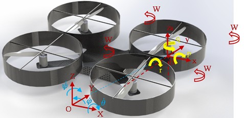
The robot in question is based on a quadrotor design, similar to those used in industry. Our goal is to create a schematic view of this robot for mathematical modeling purposes. The schematic model illustrates the construction and degrees of freedom of the quadrotor. In general, the quadrotor is shaped like a "+" with a propeller at each corner. A quadrotor’s position in space is defined using two reference frames:
1) The Fixed Reference Frame is based on the ground and is governed by Newton’s laws.
2) The Moving Reference Frame, located at the center of the quadrotor, controls its flight.
The quadrotor has four degrees of freedom: thrust, roll, pitch, and yaw. Control of the quadrotor’s movement through space is achieved by adjusting its translational and rotational speeds. Each of the four motors, positioned on the robot’s sides, rotates either clockwise or anticlockwise to maintain stability and control. Thus, the robot has four inputs (from the four motors) and six outputs, which include three translational displacements (movement along the x, y, and z axes) and three rotational displacements (roll, pitch, and yaw). To summarize the robot’s degrees of freedom, consider Table 1.
Table 1Degree of freedom in robot
Variables | Description | Interval |
z | Vertical motion | |
φ | Roll | [-ππ] |
θ | Pitch | [-π/2π/2] |
ψ | Yaw | [-ππ] |
Fig. 1Schematical degree of freedom in quadrotor robot
The nonlinear equations of the quadrotor are modeled as follows:
The parameters in Eqs. (1-8) are described in the following table [5].
In Eq. (7-10), Kf and Km represent the thrust factor and the drag factor, respectively:
These factors depend on the geometric size of the robot’s propellers and the weather conditions during the robot’s flight. Additionally, wi represents the rotational speed of the i-th propeller of the robot’s rotor. The fixed parameters of the robot for its simulation in the next chapter are presented in Table 3.
Table 2Variables on Eqs. (1-6)
Variables | Description |
Jr | Robot inertia |
p | Roll velocity |
q | Pitch velocity |
r | Yaw velocity |
Table 3Constant parameters of Quadrotor robot
Sign | Description | Value |
m | Quadrotor mass | 1 Kg |
l | Length link | 22.5 cm |
Kf | Trust factor | 9.8e-6 |
Km | Drag factor | 1.6e-7 |
Ixx | x- moment inertia | 0.0035 |
Iyy | y- moment inertia | 0.0035 |
Izz | z- moment inertia | 0.005 |
For the mathematical model of the robot, 12 state variables, 4 input variables, and 4 output variables are considered. The 12 state variables include linear and rotational displacements, as well as the speeds corresponding to each of these displacements. The four input variables comprise thrust, roll, pitch, and yaw movements:
Observe the following relationships that characterize the robot system’s state space model. The function matrices used to construct the state space model of the robot system are presented in the form of the following matrices [6]:
2.1. Robust control
In this context, the variable Z, which represents the deviations in the robot’s trajectory from the established required and preferred path, expresses the discrete relationship of the entire state space as follows:
Zk=C1[Xk]+D1[Xk]uk+D2[Xk]wk,
Yk=C2[Xk]+D3[Xk]uk+D4[Xk]wk.
The variables in Eq. (17) are defined in Table 4.
Table 4Parameters in Eq. (17)
Variable | Description |
w | Noise and disturbance |
u | Control effort |
Y | Output measurements |
Z | trajectory |
Fig. 2 presents a block diagram depicting a system with two inputs and two outputs. Before implementing the controller, it is essential to assess the open-loop block of the system without the controller to enhance understanding of the plant’s internal state and the underlying physics.
Fig. 2Robust control diagram of the system
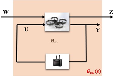
Typically, when analyzing the block and open-loop diagrams, the designer frequently considers W, which denotes unwanted inputs, disturbances, and noise arising from inherent uncertainties within the system. In the open-loop diagram, U serves as an input signal that influences the system’s dynamics and motion. For example, U represents the pressure applied to the car’s gas pedal, while W signifies potential bumps and obstructions in the vehicle’s trajectory. These uncertainties are similar to those the designer must take into account. In the open-loop block diagram, Z and Y denote the system error and the output variable of the system, respectively, with Y representing the temperature variable in the automobile engine to understand the relationship between open and closed-loop systems, a controller receives feedback from the output signal Y in the system. Depending on the theory employed in the controller, it generates the output (U) for control objectives and transmits it to the plant system. The controller is responsible for enhancing the system’s performance and stability. To improve understanding of the system’s inputs and outputs, articulate the Eq. (18) relationships in a matrix format:
The correlation between the state space (time domain) and the transformation function (frequency domain) is expressed by the following established relation. Consequently, using the system matrices from Eqs. (19-21), the transformation function G(s) can be articulated as follows:
To establish a connection between Eq. (20) and Eq. (21), we present Eq. (20), which allows us to express the final transformation function of the block diagram in Fig. 2. This equation delineates the transformation function by incorporating the control input, disturbance, and corresponding outputs, as shown below:
To fully articulate the transformation function matrix of Eq. (21), it is necessary to delineate Eq. (20), which can be divided into four distinct transformation functions. This research aims to elucidate the problem and demonstrate the relationship between the general form of the transformation function Eq. (21) and robust control, including its various categories. First, to focus on the following domains, Fig. 2 uses a more generalized block (shadowed box) that lets us focus on the relationship between the variables Z and W. This is because our main goal is to lower the system’s output value when uncertainties like W happen. We will rephrase Eq. (21) using the subsequent structure. The relationship between Fig. 2 and Eq. (22) pertains solely to the transformation function. This transformation function is designed to generate control effort and controller gain, which are subsequently inserted into the system:
The transformation function Gzw(s) can be reformulated to facilitate communication with the gain of the robust controller, as delineated in Eqs. (23):
This controller aims to enhance the infinite smoothness of the transformation function from Eq. (23) to zero by selecting the appropriate value of K. To qualitatively convey the capability of this controller, it is important to note that a performance index addresses the most significant problems, obstacles, and challenges within the robot or system:
3. Result and discussion
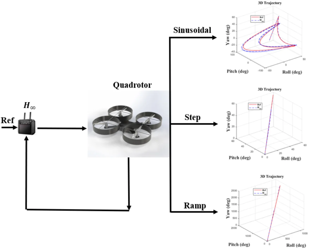
This simulation presents three possible models based on the type of input. The sine, step, and slope inputs are used to monitor the trajectory according to these reference parameters. The parameters presented include roll, pitch, and yaw angles; control error; and control effort, illustrated for all three models. In accordance with coding and modeling, they are executed in MATLAB software using two distinct environments: m-file and SIMULINK.
Fig. 3Sinusoidal results
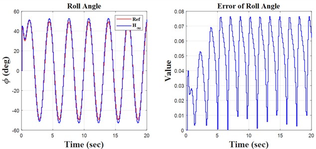
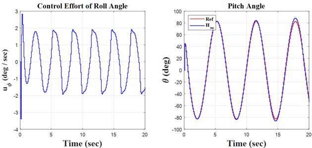
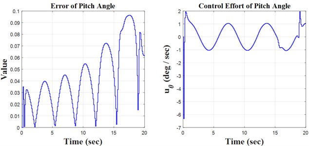
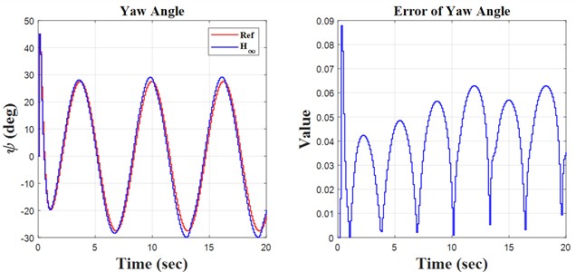
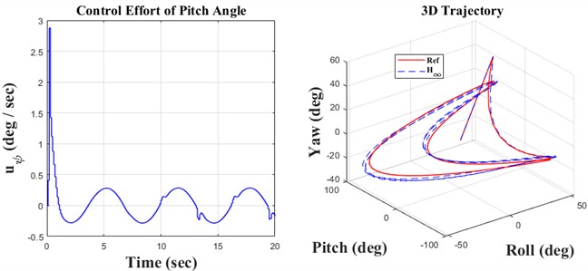
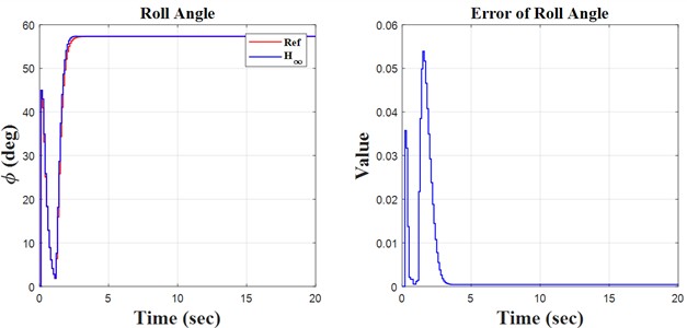
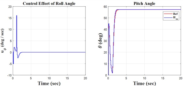
Fig. 4Step results
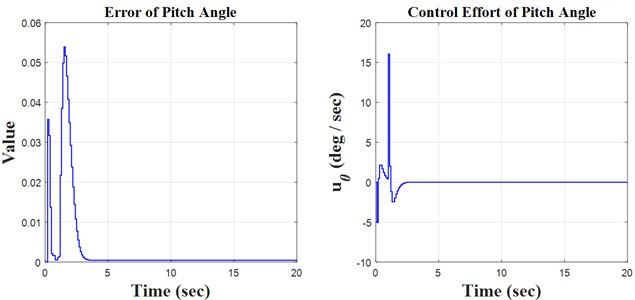
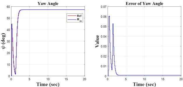
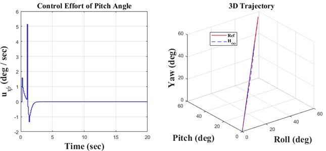
Fig. 5Ramp result
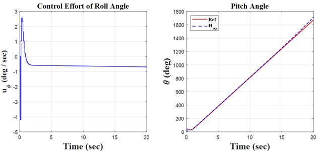
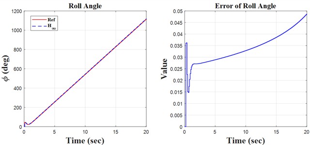
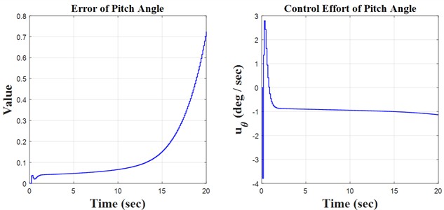
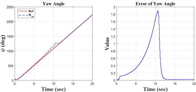
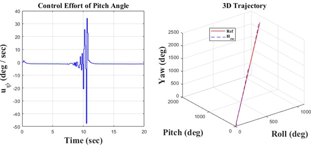
Initially, the constants are defined in the m-file coding environment, followed by the application of the SIMULINK environment to solve the quadrotor’s discrete equations. This research encompasses three key principles: monitoring the quadrotor’s trajectory using the H∞ controller and the discretization of the quadrotor’s mathematical model, both of which are distinctly illustrated in the forthcoming figures. We propose simulation models based on sinusoidal, step, and ramp inputs, which generate outputs for controlling a quadrotor, as illustrated in the following figures.
4. Conclusions
The simulation and regulation of the quadrotor using the H∞ adaptive controller are performed through discrete equations. The included diagrams and analyses facilitate the identification of notable instances of the model’s concepts and behavior. The following items can significantly aid in system recognition, design, and decision-making. This research examines the equations of motion for a quadrotor system featuring four symmetrical propellers. The equations are nonlinear due to the quadrotor’s motion, which was initially linearized around the system’s stable point. This leads to the decoupling of the equations in the directions of yaw, pitch, and roll. Following linearization, derive the transformation function of the system to facilitate the discretization of the equations. The next section aims to create a soft-based controller that is resilient, infinite, and adaptive for discrete equations. The created controller was tested with sine, step, and ramp function inputs that are set up to make it easy to create a desired path. This showed how precise the controller was by looking at how well it tracked. The outputs are analyzed as time signals, and a three-dimensional graphic is constructed based on yaw, pitch, and roll axes for enhanced comprehension. The tracking errors are illustrated in the results and discussion section. The control law is essential in the controller design process. This research examines the control rules related to the motor speeds of the installed propellers, with signals derived from all inputs. After evaluating diverse inputs and scrutinizing the outcomes, we find that the controller’s design is satisfactory regarding precision and accuracy, making it appropriate for regulating the quadrotor system.
References
-
F. Kendoul, “Survey of advances in guidance, navigation, and control of unmanned rotorcraft systems,” Journal of Field Robotics, Vol. 29, No. 2, pp. 315–378, Jan. 2012, https://doi.org/10.1002/rob.20414
-
Y. Li and S. Song, “A survey of control algorithms for quadrotor unmanned helicopter,” in 2012 IEEE Fifth International Conference on Advanced Computational Intelligence (ICACI), pp. 365–369, Oct. 2012, https://doi.org/10.1109/icaci.2012.6463187
-
K. Ogata, Discrete-Time Control Systems. Prentice-Hall, 1995.
-
K. Zhou and J. C. Doyle, Essentials of Robust Control. Prentice Hall, Upper Saddle River, 1998.
-
F. Rekabi, F. A. Shirazi, M. J. Sadigh, and M. Saadat, “Nonlinear H∞ Measurement Feedback Control Algorithm for Quadrotor Position Tracking,” Journal of the Franklin Institute, Vol. 357, No. 11, pp. 6777–6804, Jul. 2020, https://doi.org/10.1016/j.jfranklin.2020.04.056
-
P. Castillo, R. Lozano, and A. Dzul, “Stabilization of a mini-rotorcraft having four rotors,” in IEEE/RSJ International Conference on Intelligent Robots and Systems (IROS) (IEEE Cat. No.04CH37566), Vol. 3, pp. 2693–2698, Sep. 2024, https://doi.org/10.1109/iros.2004.1389815
-
A. Benallegue, A. Mokhtari, and L. Fridman, “High‐order sliding‐mode observer for a quadrotor UAV,” International Journal of Robust and Nonlinear Control, Vol. 18, No. 4-5, pp. 427–440, Mar. 2008, https://doi.org/10.1002/rnc.1225
-
H. Liu, W. Zhao, Z. Zuo, and Y. Zhong, “Robust control for quadrotors with multiple time-varying uncertainties and delays,” IEEE Transactions on Industrial Electronics, Vol. 64, No. 2, pp. 1303–1312, Feb. 2017, https://doi.org/10.1109/tie.2016.2612618
-
H. Liu, D. Li, J. Xi, and Y. Zhong, “Robust attitude controller design for miniature quadrotors,” International Journal of Robust and Nonlinear Control, Vol. 26, No. 4, pp. 681–696, Mar. 2016, https://doi.org/10.1002/rnc.3332
-
C. Li, H. Jing, J. Bao, S. Sun, and R. Wang, “Robust H∞ fault tolerant control for quadrotor attitude regulation,” Proceedings of the Institution of Mechanical Engineers, Part I: Journal of Systems and Control Engineering, Vol. 232, No. 10, pp. 1302–1313, Jun. 2018, https://doi.org/10.1177/0959651818780763
-
H. Wang, Z. Li, H. Xiong, and X. Nian, “Robust H∞ attitude tracking control of a quadrotor UAV on SO(3) via variation-based linearization and interval matrix approach,” ISA Transactions, Vol. 87, pp. 10–16, Apr. 2019, https://doi.org/10.1016/j.isatra.2018.11.015
-
B. Xian, C. Diao, B. Zhao, and Y. Zhang, “Nonlinear robust output feedback tracking control of a quadrotor UAV using quaternion representation,” Nonlinear Dynamics, Vol. 79, No. 4, pp. 2735–2752, Dec. 2014, https://doi.org/10.1007/s11071-014-1843-x
-
G. Perozzi, D. Efimov, J.-M. Biannic, and L. Planckaert, “Trajectory tracking for a quadrotor under wind perturbations: sliding mode control with state-dependent gains,” Journal of the Franklin Institute, Vol. 355, No. 12, pp. 4809–4838, Aug. 2018, https://doi.org/10.1016/j.jfranklin.2018.04.042
-
M. Chen, S. Ge, and B. Ren, “Robust attitude control of helicopters with actuator dynamics using neural networks,” IET Control Theory and Applications, Vol. 4, No. 12, pp. 2837–2854, 2010, https://doi.org/10.1049/iet-cta.2009.0478
-
E. Kayacan and R. Maslim, “Type-2 fuzzy logic trajectory tracking control of quadrotor VTOL aircraft with elliptic membership functions,” IEEE/ASME Transactions on Mechatronics, Vol. 22, No. 1, pp. 339–348, Feb. 2017, https://doi.org/10.1109/tmech.2016.2614672
-
F. Rekabi, F. A. Shirazi, and M. J. Sadigh, “Adaptive-Nonlinear H∞ hierarchical algorithm for quadrotor position tracking,” in 2018 6th RSI International Conference on Robotics and Mechatronics (IcRoM), pp. 12–17, Oct. 2018, https://doi.org/10.1109/icrom.2018.8657531
-
B. Zhao, B. Xian, Y. Zhang, and X. Zhang, “Nonlinear robust sliding mode control of a quadrotor unmanned aerial vehicle based on immersion and invariance method,” International Journal of Robust and Nonlinear Control, Vol. 25, No. 18, pp. 3714–3731, Dec. 2014, https://doi.org/10.1002/rnc.3290
-
J. Kim, M.-S. Kang, and S. Park, “Accurate modeling and robust hovering control for a quad-rotor VTOL aircraft,” in Selected papers from the 2nd International Symposium on UAVs, Reno, Nevada, U.S.A. June 8-10, 2009, pp. 9–26, Sep. 2009, https://doi.org/10.1007/978-90-481-8764-5_2
-
G. Cao, E. M.-K. Lai, and F. Alam, “Gaussian process model predictive control of an unmanned quadrotor,” Journal of Intelligent and Robotic Systems, Vol. 88, No. 1, pp. 147–162, Apr. 2017, https://doi.org/10.1007/s10846-017-0549-y
-
F. A. Goodarzi and T. Lee, “Global formulation of an extended Kalman filter on SE(3) for geometric control of a quadrotor UAV,” Journal of Intelligent and Robotic Systems, Vol. 88, No. 2-4, pp. 395–413, Mar. 2017, https://doi.org/10.1007/s10846-017-0525-6
-
G. Loianno, C. Brunner, G. Mcgrath, and V. Kumar, “Estimation, control, and planning for aggressive flight with a small quadrotor with a single camera and IMU,” IEEE Robotics and Automation Letters, Vol. 2, No. 2, pp. 404–411, Apr. 2017, https://doi.org/10.1109/lra.2016.2633290
-
N. Berman and U. Shaked, “H∞ nonlinear filtering,” International Journal of Robust and Nonlinear Control, Vol. 6, No. 4, pp. 281–296, May 1996, https://doi.org/10.1002/(sici)1099-1239(199605)6:4<281::aid-rnc233>3.0.co;2-g
About this article
The authors have not disclosed any funding.
The datasets generated during and/or analyzed during the current study are available from the corresponding author on reasonable request.
M. Hasanlu: supervision, defining model, writing-original draft preparation, and writing-review and editing. M. Siavashi: programming with software.
The authors declare that they have no conflict of interest.

