Abstract
This paper presents an investigation into the nonlinear dynamic behaviors of the floating raft isolation system coupled with quasi-zero-stiffness isolators subject to multiple disturbance sources. First, the coupling effects between the excitation source and isolation system are considered. Also, the floating raft isolation model under multiple excitations and its motion equation are deduced, and then the dynamic responses are mainly investigated by using the techniques of time history diagram, spectrum diagram, phase diagram and Poincaré map, and the bifurcation diagram. Finally, the bifurcations of the mechanical isolation system with different parameters are analyzed through numerical methods, especially the effect of center distance and mass ratio. The result predicts that the floating raft shows an alternate phenomenon of periodic motion, quasi-periodic motion, and chaotic motion when the center distance and mass ratio vary. The motion state of the floating raft vibration isolation system is more sensitive to the mass ratio than to the center distance. The horizontal and rotational response of the system becomes very intense in the chaotic state, and the response amplitudes in the horizontal and vertical directions reach the same order of magnitude. Above all, the dynamic characteristics can provide the theoretic supporting for the dynamics, vibration control and its parametric optimization of the floating raft isolation system coupled with quasi-zero-stiffness isolators. This study will lay down the requirements for the engineering design and application of floating raft isolation equipment in large vessel.
Highlights
- This study examines the nonlinear dynamic behavior of the floating raft isolation system with quasi-zero-stiffness isolators under multiple disturbances. The system shows periodic, quasi-periodic, and chaotic motions depending on center distance and mass ratio variations.
- The floating raft system is more sensitive to changes in the mass ratio than the center distance. Variations in mass ratio lead to transitions between periodic, quasi-periodic, and chaotic states, highlighting its importance in controlling system dynamics.
- In the chaotic state, the system's horizontal and rotational responses become intense, with response amplitudes in both directions reaching similar magnitudes. This emphasizes increased instability and aids in future vibration control and optimization of floating raft isolation systems.
1. Introduction
Power equipment usually causes vibration and noise. Passive vibration isolation is widely used to solve the problem of vibration transmission in power equipment due to its economical and reliable characteristics [1]. At present, passive vibration isolation devices have good vibration isolation effects in the medium and high frequency ranges, but the vibration isolation effects in the low frequency and even ultra-low frequency ranges are not ideal [2]. The shortcomings of the vibration isolation system can be compensated by introducing nonlinear vibration isolation elements with high static and low dynamic stiffness [3]. Among them, the quasi-zero stiffness vibration isolator introduces a cubic stiffness term, which can significantly improve the vibration isolation performance of the vibration isolation system in the low-frequency region.
Related research on quasi-zero-stiffness vibration isolators focuses on their geometric configuration and vibration isolation performance. References [4-6] mainly improved the vibration isolation performance in the low-frequency region by improving the structure of the single-degree-of-freedom quasi-zero-stiffness vibration isolator. Jazer et al. [7] studied a single-degree-of-freedom vibration isolation system with dual nonlinearities in stiffness and damping and found that the effect of nonlinear stiffness on the frequency response of the system is opposite to that of nonlinear damping. Xu et al. [8] proposed a multi-directional quasi-zero-stiffness isolator with time-delay active control, which can suppress low-frequency vibrations in multiple directions. Kawana et al. [9] designed a three-degree-of-freedom vibration isolator that can suppress the vertical, horizontal, and rotational vibrations of a rigid body, and found that the transient nonlinear vibration of the rigid body has a 2:1:1 internal resonance. Lu et al. [10] and Tang et al. [11] respectively designed a quasi-zero-stiffness vibration isolation platform with a 6-degree-of-freedom rigid body. The results showed that the introduction of quasi-zero-stiffness vibration isolators can improve the low-frequency vibration isolation characteristics. The quasi-zero-stiffness vibration isolators improve the vibration isolation performance remarkably in the low-frequency region. However, the chaotic phenomena make the vibration state more complex.
The quasi-zero-stiffness isolators makes the system more susceptible to chaotic phenomena that are unique to nonlinear systems, especially under the influence of large low-frequency disturbances [12]. Lou et al. [13] evaluated the vibration isolation performance of nonlinear vibration isolators in a chaotic state and found that the line spectrum amplitude was significantly reduced. Li et al. [14] and Zhang et al. [15] used time-delay control methods to deal with chaos in a two-dimensional vibration isolation raft system and studied the stability of different time-delay feedback control methods. Based on a simplified two-dimensional raft system model, Zhang et al. [16] fully presented the line spectrum chaos method of nonlinear time-delay feedback control and explored the influence of control parameters on the chaotic effect of the system under multi-source excitation conditions. Chai et al. [17] used double-delay feedback control to make a high-static and low-dynamic vibration isolation system chaotic, while weakening the line spectrum characteristics and intensity. Zuo et al. [18] used the open-loop plus nonlinear closed-loop coupling method to realize the generalized chaotic synchronization, which can achieve the dual functions of concealing the line spectrum information and maintaining the vibration isolation performance. Obviously, when quasi-zero-stiffness isolators are applied to vibration isolation systems, it is inevitable to pay attention to their nonlinear vibration phenomena.
Existing research on quasi-zero-stiffness vibration isolation systems focuses on single-degree-of-freedom vibration isolation or double-layer vibration isolation [19-23]. Lu et al. [24] placed quasi-zero-stiffness isolators on the upper and lower layers of a double-layer vibration isolation system and found that the stiffness nonlinearity of the lower layer had a greater impact on the vibration isolation performance of the system than that of the upper layer. Ji et al. [25] explored the vibration isolation performance of two-degree-of-freedom quasi-zero stiffness isolators under different parameters. The study found that the damping ratio and the vertical stiffness ratio can improve the low-frequency vibration isolation performance. Zhao et al. [26] established a vertical vehicle-quasi-zero stiffness floating plate track coupling dynamic model and found that excessively high nonlinear stiffness levels would weaken the vibration isolation effect in the resonance and high-frequency regions. Zhang et al. [27] established the raft dynamic equation considering the foundation flexibility and the nonlinear stiffness of the isolator, and analyzed the vertical vibration of the system under single-frequency and multi-frequency excitation. Zhao et al. [28] established the dynamic equations of the airbag raft-rotor system considering the vertical and horizontal vibrations of the raft body, and analyzed the nonlinear characteristics of the system such as bifurcation and chaos under a single vibration excitation source. Li et al. [29] introduced the quasi-zero-stiffness isolator into the floating raft vibration isolation system and established a high-dimensional coupled dynamic equation with 12 degrees of freedom. They found that its vibration isolation performance was significantly improved, but did not analyze the nonlinear characteristics of the system. Li et al. [30] established a 6-degree-of-freedom vibration isolation model composed of eight isolators to solve the complex problem of rolling and pitching motions of ocean-going vessels. Wei et al. [31] designed a 2-degree-of-freedom bottom-springs grounded nonlinear vibration isolator model, and carried out numerical simulation under typical harmonic excitation. The results showed that the model has a good vibration isolation effect. Sun et al. [32] adopted the improved Incremental Harmonic Balance Method to discuss the coupling relationship between different degrees of freedom of the quasi-zero stiffness Gough-Stewart vibration isolation platform, considering the coupling relationship between each degree of freedom.
However, it is worth mentioning that researchers’ works mainly concentrated on either single-degree-of-freedom or double-layer vibration isolation while the floating raft vibration isolation with quasi-zero-stiffness isolators is not referred. In addition, the excitation resource from their research is always a single vibration excitation source, and the definition of excitation was not accurate enough to describe the real movement of the floating raft.
In this paper, an investigation into the nonlinear dynamic behaviors of the floating raft isolation system coupled with quasi-zero-stiffness isolators under multiple disturbance sources is presented. First, the coupling effects between the excitation source and isolation system are considered, and movements in the vertical, horizontal, and rotational directions are also taken into account. Based on this, the floating raft isolation model subjected to multiple disturbance sources and its motion equation is developed, and then its dynamic responses are mainly investigated by using the techniques of time history diagram, spectrum diagram, phase diagram, Poincaré diagram, and the bifurcation diagram. Last, the bifurcations of the floating raft isolation system with different parameters are analyzed through numerical methods, especially the effect of center distance and mass ratio. In particular, this work aims to present the theoretic supporting for the dynamics, vibration control and its parametric optimization of the floating raft isolation system coupled with quasi-zero-stiffness isolators.
2. Modeling of the floating raft vibration isolation system
2.1. Dynamics modeling
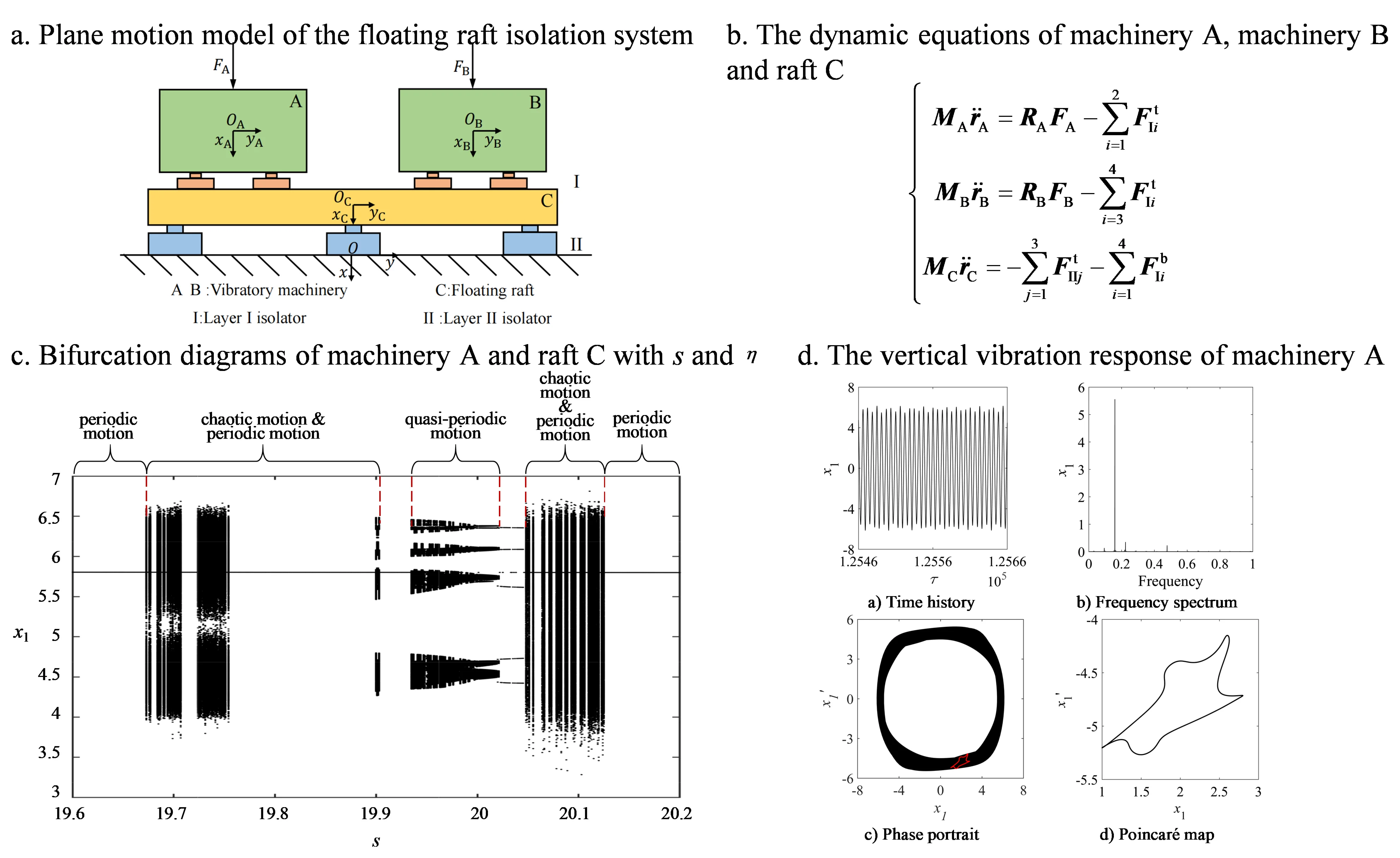
A plane motion model is established for the floating raft vibration isolation system considering multi-disturbance sources, as shown in Fig. 1. The plane motion model includes five parts: machinery A, machinery B, upper vibration isolator I, lower vibration isolator II, and raft C.
Fig. 1Plane motion model of the floating raft isolation system
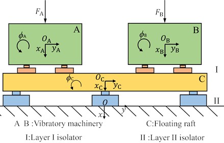
The floating raft vibration isolation system is modeled by the multi-rigid body dynamic method. The machinery and raft are regarded as rigid bodies. A couple of quasi-zero-stiffness vibration isolators are vertically installed under each machinery, and three quasi-zero-stiffness vibration isolators are vertically installed under the raft. The foundation is rigidly fixed. As shown in Fig. 1, the mass centers of machinery A, machinery B and raft C are set as the origins of their local coordinate systems , , , respectively. , , are the ordinate axes of the local coordinate systems, and their directions are perpendicular to the geodetic plane where the system is located. , , are the horizontal axes of the local coordinate systems, and their directions are parallel to the geodetic plane. , , represents the rotation angles of machinery A, machinery B and raft C in the plane, respectively. Set the origin of the global coordinate system at point . , are the ordinate axis and horizontal axis of the overall coordinate system.
The dynamic equations of machinery A, machinery B and raft C are established respectively based on Newton's second law, which is formulated in Eq. (1):
In the equilibrium equation of machinery A, represents the mass matrix of machinery A. and represent the mass and planar moment of inertia, respectively. represents the acceleration vector of the center of machinery A. represents the transformation matrix of the local coordinate system to the overall coordinate system for machinery A, which can be expressed as Eq. (2). represents the simple harmonic excitation vector of machinery A. Assuming the machinery is only subjected to vertical excitation, the excitation amplitude is and the excitation frequency is . represents the restoring forces at the top ends of the upper vibration isolator I. The subscript indicates the th vibration isolator in the upper level I. Superscript represents the top end of the isolator:
Similarly, in the equilibrium equation of machinery B, , represent the mass matrix, acceleration array and simple harmonic excitation array of machinery B, respectively. represents the phase difference between motivation and . represents the transformation matrix of the local coordinate system to the overall coordinate system for machinery B, and it is formulated in the same form as .
Similarly, in the equilibrium equation of raft C, and represent the mass matrix and acceleration vector of raft C, respectively. represents the restoring forces acting on the top end of the lower vibration isolator II. represents the restoring forces at the bottom end of the upper vibration isolator I. The subscript indicates the th vibration isolator in the lower level II. Superscript represents the bottom end of the isolator.
Both the upper vibration isolator I and the lower vibration isolator II are selected as quasi-zero-stiffness vibration isolators. Their restoring forces , and can be expressed as , where is the deformation, is the stiffness coefficient, is the cubic nonlinear stiffness coefficient.
The stiffness coefficient matrix and damping coefficient matrix of the upper vibration isolator I are , . , and are the stiffness coefficients of the upper vibration isolator I in the vertical, horizontal and rotational directions. Accordingly, , and are the damping coefficients of the upper vibration isolator I in the vertical, horizontal and rotational directions.
The stiffness coefficient matrix and damping coefficient matrix of the lower vibration isolator II are , . , and are the stiffness coefficients of the lower vibration isolator II in the vertical, horizontal and rotational directions. Accordingly, , and are the damping coefficients of the lower vibration isolator II in the vertical, horizontal and rotational directions.
At the same time, the frequency parameters corresponding to the stiffness matrix can be obtained, as shown in Table 1.
Table 1Frequency parameters
Parameter | Expression | Parameter | Expression |
The equilibrium equations of the upper vibration isolator I and the lower vibration isolator II are formulated. And their restoring forces are expressed as:
Among them:
where, and represents the translation transformation matrix of the top end of the upper vibration isolator I in the global coordinate system. The specific form is expressed as follows:
where and represents the coordinates of the upper end of the upper isolator I in the local coordinate system. The meaning and form of , , and are similar to , which needs no further elaboration:
where and represents the deformation and velocity when the coordinates of the top end of the upper isolator I are in the local coordinate system. , , , , , and have similar meaning and form as and , which needs no further elaboration.
2.2. Dimensionless kinetic equations
Define characteristic length, , characteristic angle, , and the planar moment of inertia of the raft, :
where indicates the height of machinery A, and respectively represents the width and height of raft C. The plane moment of inertia of machinery A and machinery B, and have similar form as .
Define two dimensionless parameters: centroid distance and mass ratio . Centroid distance indicates the horizontal distance from the machinery center to the raft center, which is divided by the characteristic length . Mass ratio represents the mass of the raft and machinery A :
In addition to considering the centroid distance and mass ratio , the following dimensionless parameters are further introduced, as shown in Table 2.
Table 2Dimensionless parameters
Parameter | Expression | Parameter | Expression | Parameter | Expression |
Note: , and respectively represent the width of machinery A, machinery B and machinery C, , and indicates the height of machinery A, machinery B and machinery C | |||||
Substituting the above dimensionless parameters into Eq. (1), it can obtain the dimensionless kinetic equation:
Among them:
In Eq. (12), the superscripts and denote the dimensionless time derivative and superscript indicates dimensionless parameter. , and represent the mass, damping and linear stiffness matrices of the system, respectively. represents the nonlinear restoring force. represents the simple harmonic excitation of the system, where and are formulated as follows:
Considering a floating raft device of a diesel generator set, it is feasible to determine the value and variation range of the dimensionless parameters. The upper vibration isolator I is arranged symmetrically about the machinery center, and the lower vibration isolator II is arranged symmetrically about the raft center. External excitation frequency is . Excitation period is . Excitation amplitude is . The values of dimensionless parameters involved in the kinetic equation are shown in Table 3.
Table 3Dimensionless parameters value
Parameter | Expression | Parameter | Expression | Parameter | Expression |
0.084 | 1.00 | 1.00 | |||
0.092 | 1.00 | 1.00 | |||
12.77 | 1.88 | 1.00 | |||
12.77 | 0.89 | 1.00 | |||
34.60 | 0.89 | /2 | |||
2.09 | 1.50 | ||||
2.09 | 1.12 | ||||
8.65 | 0.015 | ||||
0.80 | 0.015 | ||||
0.30 | 0.015 | ||||
0.015 | |||||
0.015 | |||||
0.015 |
3. Bifurcation characteristics of the floating raft vibration isolation system
Parameter analysis is carried on bifurcation characteristics of the floating raft vibration isolation system with quasi-zero-stiffness. Since machineries A and B are arranged symmetrically, only the movement of machinery A and raft C is considered. The fourth-order Runge-Kutta method is used to solve the nonlinear dynamic equations, with the time step is specified as .
3.1. The influence of the distance between the centroids
Centroid distance is a dimensionless parameter reflecting the installation distance between machinery A and machinery B. Fig. 2 shows the bifurcation diagram of the steady-state displacement response of machinery A as the centroid distance varies.
Fig. 2Bifurcation diagrams of machinery A with s
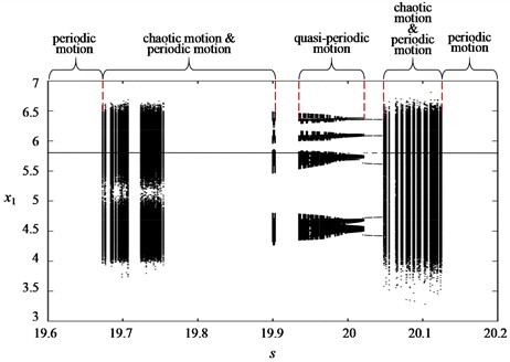
a) Vertical response bifurcation diagram of machinery A
b) Horizontal response bifurcation diagram of machinery A
c) Rotation response bifurcation diagram of machinery A
As shown in Fig. 2, the motions of machinery A in vertical and horizontal direction have close trend with the centroid distance . Since the excitation direction is vertical, the vibration amplitude of vertical motion is larger. When the centroid distance > 19.68, the motion of machinery A shows an alternating state of periodic motion and chaotic motion. When the centroid distanceis between 19.94 and 20.02, the motion of machinery A in three directions transforms into quasi-periodic motion. As the centroid distancecontinues to increase, the motion goes through a period of alternating periodic motion and chaotic motion, and then transforms into periodic motion. It is worth noting that machinery A has no single-period motion. That is because the vertical and horizontal directions of machinery A provide coupling stiffness for the rotation direction. The rotation response of machinery A is affected by the movement in the other two directions, and the movement state is more complicated.
In general, under the motivation of vertical equal-amplitude double excitation with a phase difference of /2, the motion of machinery A conforms to the law of period-chaos-period according to the centroid distance.
Fig. 3Bifurcation diagrams of raft C with s
a) Vertical response bifurcation diagram of floating raft C
b) Horizontal response bifurcation diagram of floating raft C
c) Rotation response bifurcation diagram of floating raft C
Fig. 3 is the bifurcation diagram of the steady-state displacement response of raft C as the distance from the mass center varies. Similar to the movement of machinery A, the movement of raft C in all directions varies according to the centroid distance. The variation rules are basically similar With the centroid distance, the motion of the raft C in all directions first shows a stable periodic motion, followed by an alternating state of periodic motion, quasi-periodic motion, multi-periodic motion, and chaotic motion. Compared with machinery A, the vibration amplitude of raft C in all directions is smaller. However, in the unstable quasi-periodic motion state, the bifurcation of the raft C is more complex and the nonlinear vibration characteristics are more obvious.
In summary, when the value of the centroid distance approaches 20, the movement of the floating raft vibration isolation system will be greatly affected. The system movement will produce more obvious quasi-periodic motion and chaotic motion, and the movement in the three directions will become more unstable. Especially for horizontal movement and rotation, the vibration amplitude will be greatly increased.
Therefore, in order to avoid the nonlinear motion state in the process of system motion, this value range 19.6-20.2 should be excluded in the design of floating raft isolation system. It can be seen from the above that , , so can be optimized by designing the vertical stiffness coefficient of the upper vibration isolator.
3.2. The influence of the mass ratio
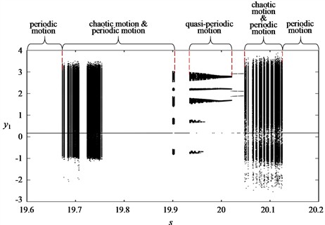
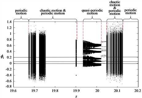
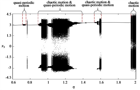
Mass ratio is a dimensionless parameter reflecting the mass ratio between raft C and machinery A. Fig. 4 is the bifurcation diagram of the steady-state displacement response of machinery A as the mass ratio varies.
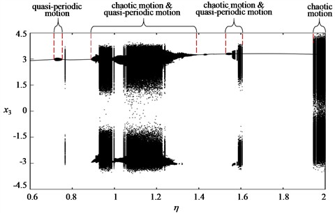
Fig. 4Bifurcation diagrams of machinery A with η
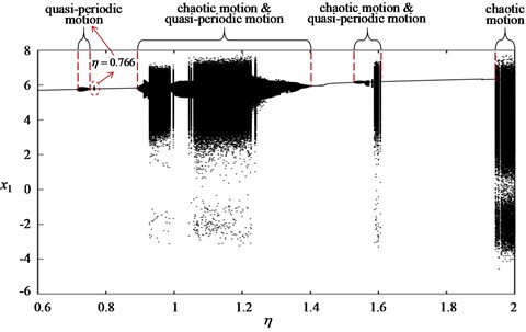
a) Vertical response bifurcation diagram of machinery A
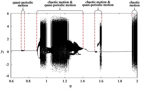
b) Horizontal response bifurcation diagram of machinery A
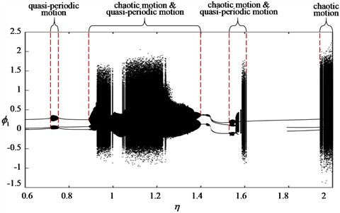
c) Rotation response bifurcation diagram of machinery A
It can be seen from the Fig. 4 that the displacement response of machinery A in each direction varies with the mass ratio . There are multiple discontinuous quasi-periodic motion intervals and chaotic motion intervals in the variation. When the mass ratio 0.890, the motion state of machinery A is stable. The motion of machinery A comes into a quasi-periodic state when the mass ratio is between 0.716 and 0.750 and at 0.766. It is in periodic motion in the rest of the value range. When the mass ratio is in the range of 0.892 and 1.398, the motion of machinery A in all directions entered an obvious nonlinear motion state. In particular, its horizontal response entered chaos through period-doubling bifurcation, and the vibration amplitudes in all directions oscillated over a large range. Quasi-periodic motion states and chaotic motion states appears alternately, and the vibration amplitude in the horizontal direction reaches the same order of magnitude as that in the vertical direction. After the mass ratio exceeding 1.400, quasi-periodic motion and chaotic motion states only appear between 1.530-1.606 and 1.944-2.000, and the rest of the value range is periodic motion.
In general, the motion of machinery A shows a pattern of alternating periodic-quasi-periodic-chaotic appearance according to the increment of mass ratio .
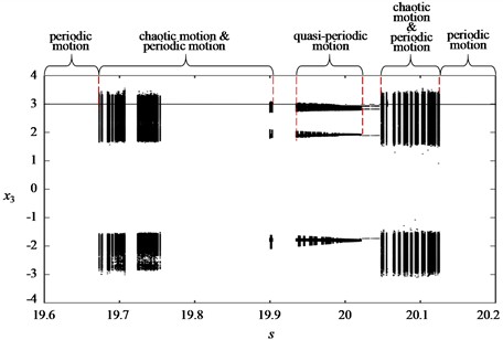
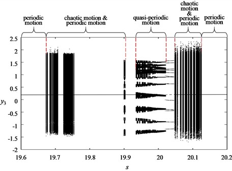
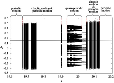
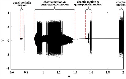
Fig. 5 is the bifurcation diagram of the steady-state displacement response of raft C as the mass ratio changes. Similar to the movement of machinery A, the movement of raft C in all directions varies with the mass ratio. As the mass ratio increases, the motion of the raft C in all directions first shows a stable periodic motion, followed by periodic motion, quasi-periodic motion, multi-periodic motion, and chaotic motion. Compared with machinery A, the vibration amplitude of raft C in all directions is smaller. At the same time, the rotation response of raft C also has the phenomenon of entering a chaotic state by period-doubling bifurcation.
Fig. 4(c) and Fig. 5(c) reveal that the rotational response of machinery A and raft C varies with the mass ratio . In the bifurcation characteristics, there is also a period-doubling bifurcation phenomena, which is also caused by the coupling stiffness in the rotation direction.
In summary, in order to avoid the nonlinear motion state during the system motion, the mass ratio should avoid the value ranges of 0.892-1.398, 1.530-1.606 and 1.944-2.000. The mass ratio is optimized by designing the raft mass and the machinery A mass .
4. Chaotic characteristics of the floating raft vibration isolation system
In nonlinear systems, the Lyapunov exponent is a quantitative analysis method to identify chaotic motion. When the maximum Lyapunov exponent is positive, the system is in a chaotic state; otherwise, the system is in a periodic or quasi-periodic motion state. From the analysis in Section 3.2, we can see that the mass ratio, has more obvious and complex impact on the vibration characteristics of the system. Therefore, it is necessary to use the Lyapunov exponent to further analyze the nonlinear characteristics of the system.
Fig. 5Bifurcation diagrams of raft C with η
a) Vertical response bifurcation diagram of floating raft C
b) Horizontal response bifurcation diagram of floating raft C
c) Rotation response bifurcation diagram of floating raft C
This section adopts the Benettin method [33]to calculate the maximum Lyapunov index of the floating raft vibration isolation system based on the orbit perturbation principle. The initial condition of the phase trajectory is , , . Fig. 6 plots the curve of maximum Lyapunov exponent versus mass ratio . By comparing Fig. 6 with Fig. 4, it can be found that the maximum Lyapunov exponent of the system is basically consistent with the period-doubling bifurcation diagram. As the mass ratio increases, when the system motion is in a periodic motion state, the maximum Lyapunov exponent is negative, when the system motion is in a chaotic motion state, the maximum Lyapunov exponent is positive.
In general, it also shows the evolution law of nonlinear vibration characteristics with alternating periodic motion, quasi-periodic motion, and chaotic motion. The local stability of the system can be further analyzed based on the Lyapunov exponent.
Fig. 6LLE diagram of floating raft system with η
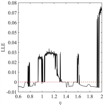
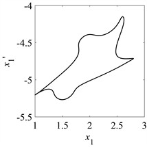
Fig. 7 shows the time history diagram, spectrum diagram, phase diagram and Poincaré map of the vertical vibration response of machinery A when mass ratio 1.002. The time history diagram in Fig. 7(a) depicts the steady-state vibration response, and the vibration amplitude fluctuates periodically within a certain range. The spectrum diagram in 7(b) shows that there are obvious double frequency components in the system. The phase diagram in Fig. 7(c) plots the steady-state vibration response and the velocity numerical solution, and the phase trajectory forms a ring with a certain width. Fig. 7(d) Poincaré map with 2000 intervals . The points of the curve are drawn, and their Poincaré mapping points form a closed curve. Based on the results in Fig. 7, machinery A is in a quasi-periodic motion state at this time.
Fig. 7Machinery A is in a quasi-periodic motion at η= 1.002
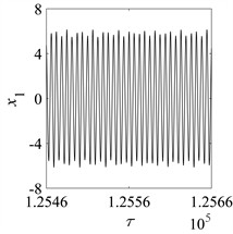
a) Time history
b) Frequency spectrum
c) Phase portrait
d) Poincaré map
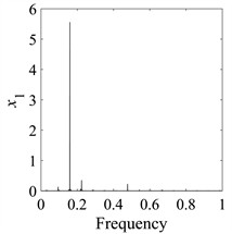
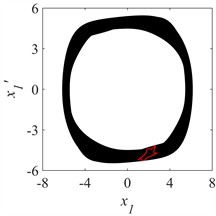
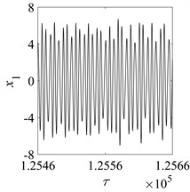
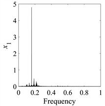
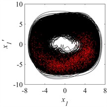
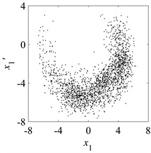
Fig. 8 shows time history diagram, spectrum diagram, phase diagram and Poincaré map of the vertical vibration response of machinery A when the mass ratio 1.050. Fig. 8(a) depicts the steady-state vibration response, and the vibration amplitude fluctuates periodically within a certain range. The spectrum diagram in 8(b) shows that there are complex frequency components in the system and continuous frequency. Fig. 8(c) plots the steady-state vibration response and the velocity numerical solution, and the phase trajectory is messy which indicates unstable state. Fig. 8(d) plots Poincaré map with 2000 intervals . The points scattered in a certain area. Based on the results in Fig. 8, machinery A is currently exhibiting chaotic motion state.
Fig. 8Machinery A is in chaotic motion at η= 1.050
a) Time history
b) Frequency spectrum
c) Phase portrait
d) Poincaré map
5. Conclusions
The nonlinear dynamic behavior of a floating raft isolation system coupled with quasi-zero-stiffness isolators under multiple disturbance sources is carried out. In this study, based on the multi-rigid body dynamic theory, the mathematical model of the 9-degree-of-freedom system is developed. And its nonlinear dynamic characteristics are analyzed by applying the Runge-Kutta method. The dynamic responses are mainly investigated by using time history diagram, spectrum diagram, phase diagram, Poincaré diagram, and the bifurcation diagram. The results of this research significantly extend and enrich the understanding of the behavior of the system. Based on the results of the numerical simulations, the following conclusions can be summarized. First, the floating raft exhibits alternate phenomenon of periodic motion, quasi-periodic motion, and chaotic motion when the center distance and mass ratio vary. The motion state of the floating raft vibration isolation system is more sensitive to the mass ratio than to the center distance. Second, the horizontal and rotational responses of the system become very intense in the chaotic state, with the response amplitudes in the horizontal and vertical directions reaching the same order of magnitude. Above all, the dynamic characteristics can provide theoretic supporting for the dynamics, vibration control, and parametric optimization of the floating raft isolation system coupled with quasi-zero-stiffness isolators. This study is based on the basic assumption that the external excitation phase difference is /2, which cannot fully reflect the real system working scenario. In the future, it is planned to carry out research on different phase differences.
References
-
L. Gu and J. Min, “Review of vibration and noise control technology for submarines,” Ship Science and Technology, Vol. 41, No. 23, pp. 1–5, 2019, https://doi.org/cnki:sun:jckx.0.2019-23-002
-
Z. Yang, C. Shuai, B. Li, and J. Ma, “Low frequency passive vibration isolation technology and its application prospect in ship equipment,” in Second International Conference on Cloud Computing and Mechatronic Engineering (I3CME 2022), p. 75, Sep. 2022, https://doi.org/10.1117/12.2655026
-
Z. Q. Lu and L. Q. Chen, “Some recent progresses in nonlinear passive isolations of vibrations,” Chinese Journal of Theoretical and Applied Mechanics, Vol. 49, No. 3, pp. 550–564, 2017, https://doi.org/10.6052/0459-1879-17-064
-
N. Liu and Y. Z. Guo, “Research on nonlinear dynamic vibration absorber type quasi-zero stiffness vibration isolator,” Mechanical Research and Application, Vol. 33, No. 6, pp. 24–30, 2020, https://doi.org/10.16576/j.cnki.1007-4414.2020.06.008
-
J. C. Niu, W. J. Zhang, Y. J. Shen, and J. Wang, “Subharmonic resonance of quasi-zero Stiffness vibration isolation System with Compound dry friction,” Chinese Journal of Theoretical and Applied Mechanics, Vol. 54, No. 4, pp. 1092–1101, 2022, https://doi.org/10.6052/0459-1879-21-680
-
Z. K. Peng and Z. Q. Lang, “The effects of nonlinearity on the output frequency response of a passive engine mount,” Journal of Sound and Vibration, Vol. 318, No. 1-2, pp. 313–328, Nov. 2008, https://doi.org/10.1016/j.jsv.2008.04.016
-
G. N. Jazar, R. Houim, A. Narimani, and M. F. Golnaraghi, “Frequency response and jump avoidance in a nonlinear passive engine mount,” Journal of Vibration and Control, Vol. 12, No. 11, pp. 1205–1237, Nov. 2006, https://doi.org/10.1177/1077546306068059
-
J. Xu and X. Sun, “A multi-directional vibration isolator based on quasi-zero-stiffness structure and time-delayed active control,” International Journal of Mechanical Sciences, Vol. 100, pp. 126–135, Sep. 2015, https://doi.org/10.1016/j.ijmecsci.2015.06.015
-
R. Kawana, T. Tokoyoda, K. Sato, M. Yoshizawa, and T. Sugiura, “Passage through resonance in a three degree-of-freedom vibration isolation system,” in ASME 2005 International Design Engineering Technical Conferences and Computers and Information in Engineering Conference, pp. 1907–1915, Jan. 2005, https://doi.org/10.1115/detc2005-85171
-
Z.-Q. Lu, D. Wu, H. Ding, and L.-Q. Chen, “Vibration isolation and energy harvesting integrated in a Stewart platform with high static and low dynamic stiffness,” Applied Mathematical Modelling, Vol. 89, pp. 249–267, Jan. 2021, https://doi.org/10.1016/j.apm.2020.07.060
-
J. Tang, Y. Yang, Y. Li, and D. Cao, “A 6-DOF micro-vibration isolation platform based on the quasi-zero-stiffness isolator,” Proceedings of the Institution of Mechanical Engineers, Part C: Journal of Mechanical Engineering Science, Vol. 235, No. 22, pp. 6019–6035, May 2021, https://doi.org/10.1177/09544062211010831
-
P. S. Harvey Jr., R. Wiebe, and H. P. Gavin, “On the chaotic response of a nonlinear rolling isolation system,” Physica D: Nonlinear Phenomena, Vol. 256-257, pp. 36–42, Aug. 2013, https://doi.org/10.1016/j.physd.2013.04.013
-
J.-J. Lou, S.-J. Zhu, L. He, and Q.-W. He, “Experimental chaos in nonlinear vibration isolation system☆,” Chaos, Solitons and Fractals, Vol. 40, No. 3, pp. 1367–1375, May 2009, https://doi.org/10.1016/j.chaos.2007.09.053
-
Y. Li, D. Xu, Y. Fu, and J. Zhou, “Chaotification of a nonlinear vibration isolation system by dual time delayed feedback control,” International Journal of Bifurcation and Chaos, Vol. 23, No. 6, p. 1350096, Jul. 2013, https://doi.org/10.1142/s021812741350096x
-
J. Zhang, D. Xu, J. Zhou, and Y. Li, “Chaotification of vibration isolation floating raft system via nonlinear time-delay feedback control,” Chaos, Solitons and Fractals, Vol. 45, No. 9-10, pp. 1255–1265, Sep. 2012, https://doi.org/10.1016/j.chaos.2012.05.012
-
J. Zhang, D.-L. Xu, Y.-L. Li, and J.-X. Zhou, “Line spectrum chaotification of a double-layer vibration isolation floating raft system under multi-source excitation,” Acta Physica Sinica, Vol. 63, No. 18, p. 180505, Jan. 2014, https://doi.org/10.7498/aps.63.180505
-
K. Chai, J. J. Lou, Q. C. Yang, and X. Yu, “Vibration isolation system based on high-static-low-dynamic-stiffness with dual time-delay feedback control,” Journal of Ship Mechanics, Vol. 23, No. 5, pp. 611–620, 2019, https://doi.org/10.3969/j.issn.1007-7294.2019.05.013
-
Z. L. Zuo, X. Yu, S. Li, K. Chai, and S. Y. Liu, “Line spectrum reduction of a vibration isolation system via chaotic synchronization and migration control,” Journal of Vibration and Shock, Vol. 40, No. 16, pp. 245–252, 2021, https://doi.org/10.13465/j.cnki.jvs.2021.16.031
-
J. Yang, Y. P. Xiong, and J. T. Xing, “Vibration power flow and force transmission behaviour of a nonlinear isolator mounted on a nonlinear base,” International Journal of Mechanical Sciences, Vol. 115-116, No. 3, pp. 238–252, Sep. 2016, https://doi.org/10.1016/j.ijmecsci.2016.06.023
-
D. Shao, Z. Q. Lu, and L. Q. Chen, “Power flow characteristics of a two-stage nonlinear vibration isolation system,” Journal of Vibration Engineering, Vol. 30, No. 5, pp. 764–773, 2017, https://doi.org/10.16385/j.cnki.issn.1004-4523.2017.05.009
-
Y. Liu, W. Ji, E. Deng, X. Wang, and C. Song, “Dynamic characteristics of two degree-of-freedom quasi-zero stiffness vibration isolation system with nonlinear springs,” Mechanics Based Design of Structures and Machines, Vol. 51, No. 6, pp. 3100–3118, Jun. 2023, https://doi.org/10.1080/15397734.2021.1919142
-
W. Wu and B. Tang, “The elliptic harmonic balance method for the performance analysis of a two‐stage vibration isolation system with geometric nonlinearity,” Shock and Vibration, Vol. 2021, Feb. 2021, https://doi.org/10.1155/2021/6690686
-
Z. Lu, M. J. Brennan, T. Yang, X. Li, and Z. Liu, “An investigation of a two-stage nonlinear vibration isolation system,” Journal of Sound and Vibration, Vol. 332, No. 6, pp. 1456–1464, Mar. 2013, https://doi.org/10.1016/j.jsv.2012.11.019
-
Z. Q. Lu, D. Shao, H. Ding, and L. Q. Chen, “Power flow in a two-stage nonlinear vibration isolation system with high-static-low-dynamic stiffness,” Shock and Vibration, 2018, https://doi.org/10.3969/j.issn.1672-6413.2017.01.011
-
Z.-Q. Lu, D. Shao, H. Ding, and L.-Q. Chen, “Power flow in a two‐stage nonlinear vibration isolation system with high‐static‐low‐dynamic stiffness,” Shock and Vibration, Vol. 2018, No. 1, pp. 200–210, May 2018, https://doi.org/10.1155/2018/1697639
-
Z. M. Zhao, K. Wei, J. J. Ren, G. F. Xu, X. G. Du, and P. Wang, “Vibration response analysis of floating slab track supported by nonlinear quasi-zero-stiffness vibration isolators,” Journal of Zhejiang University-SCIENCE A, Vol. 22, No. 1, pp. 37–52, 2021, https://doi.org/10.19636/j.cnki.cjsm42-1250/o3.2020.046
-
S. Z. Zhang and Q. Chen, “The non-resonant response research on flexible floating raft isolation system,” Journal of Vibration Engineering, Vol. 27, No. 3, pp. 326–332, 2014, https://doi.org/10.3969/j.issn.1004-4523.2014.03.003
-
W. Zhao, M. Li, and Y. Liu, “Nonlinear dynamics of marine rotor system coupled with air bag-floating raft subjected to the basement excitations in lateral directions,” Shock and Vibration, Vol. 2020, pp. 1–20, Jan. 2020, https://doi.org/10.1155/2020/8572178
-
Y. Li and D. Xu, “Vibration attenuation of high dimensional quasi-zero stiffness floating raft system,” (in Chinese), International Journal of Mechanical Sciences, Vol. 126, pp. 186–195, Jun. 2017, https://doi.org/10.1016/j.ijmecsci.2017.03.029
-
B.-Y. Li, C.-G. Shuai, and J.-G. Ma, “Mechanical characteristics analysis of high dimensional vibration isolation systems based on high-static-low-dynamic stiffness technology,” Scientific Reports, Vol. 14, No. 1, p. 8195, Apr. 2024, https://doi.org/10.1038/s41598-024-58469-x
-
C. Wei, “H-infinity optimal control based on output feedback for nonlinear two-degree-of-freedom vibration isolator with quasi-zero stiffness,” Acta Mechanica, Vol. 235, No. 10, pp. 6365–6378, Aug. 2024, https://doi.org/10.1007/s00707-024-04042-6
-
K. Sun, J. Tang, Z. Wu, Y. Li, and D. Cao, “Coupled nonlinear vibration characteristics of quasi-zero-stiffness Gough-Stewart isolation platform,” Aerospace Science and Technology, Vol. 152, p. 109352, Sep. 2024, https://doi.org/10.1016/j.ast.2024.109352
-
G. Benettin, L. Galgani, and J.-M. Strelcyn, “Kolmogorov entropy and numerical experiments,” Physical Review A, Vol. 14, No. 6, pp. 2338–2345, Dec. 1976, https://doi.org/10.1103/physreva.14.2338
About this article

This work was supported by the National Natural Science Foundation of China (Grant Nos. 52108450).
The datasets generated during and/or analyzed during the current study are available from the corresponding author on reasonable request.
Ming Fang: conceptualization, data curation, formal analysis, investigation, methodology; resources, writing-original draft, funding acquisition. Zhengong Shi: software, validation. Shuo Xing: supervision, writing-review and editing. Miao Zhang: project administration. Zhipeng Li: project administration, resources.
The authors declare that they have no conflict of interest.
