Abstract
Due to challenges faced during demolition and blasting processes such as conducting prototype monitoring tests on large continuous multi-span structures or carrying out full-area dynamic monitoring of overall structural stress; This paper takes the demolition of the Ruzhou Unicom building as the background, optimizes the design of the demolition and blasting program through theoretical analysis and simulation monitoring, and also studies the form of structural instability movement and the deformation of the key parts of the damage and internal force characteristics, and obtains the following conclusions: the axial force reaches the maximum value when the building is not deflected; when the first-order derivative of the shear force is 0, the maximum shear stress occurs at the position of 2/3 of the height of the building; When the first-order derivative of bending moment is 0, the maximum bending moment occurs at 1/3 of the building height. In Mushroom Pavilion incision formation, the support part of the main structure produces a downward force, exacerbating the disintegration of the main part of the damage; the main structure of the collapse process, the back row of columns are mainly presented as bending shear damage, the upper side beams are mainly presented as tensile damage, the central and lower side beams are mainly presented as compression shear damage. Notably, the bidirectional notch configuration results in a forward displacement of 9.5 meters and a subsequent recoil of 4.6 meters, providing effective shielding for the military fiber-optic cables positioned at the forefront and the adjacent deep excavation pits. Additionally, this configuration facilitates the rapid establishment of a stable collapse pattern between the Mushroom Pavilion structure and its main body, ultimately accelerating the disintegration of the overall building structure during the collapse event.
Highlights
- the axial force reaches the maximum value when the building is not deflected.
- when the first-order derivative of the shear force is 0, the maximum shear stress occurs at the position of 2/3 of the height of the building.
- When the first-order derivative of bending moment is 0, the maximum bending moment occurs at 1/3 of the building height.
- Mushroom Pavilion does not open the incision, the building collapse process is prone to forward phenomenon.
- two-way micro-folding blasting program can effectively avoid the occurrence of forward problem, and make the volume of the explosion pile is smaller, better protection of the front ancillary facilities.
- Mushroom Pavilion incision formation, the support part of the main structure to produce a downward force, exacerbating the disintegration of the main part of the damage.
1. Introduction
With the implementation of the national “urban renewal” strategy, there has been an increasing trend in the demolition and blasting of buildings in complex environments. As a prevalent structural form in high-rise buildings, the design and optimization of demolition and blasting programs, as well as studies on structural instability, have become focal points within engineering and academic circles. In actual continuous multi-span frame shear demolition projects, due to their massive scale and intricate conditions, it is challenging to conduct effective prototype tests for real-time monitoring of structural collapse processes and internal force changes [1]. Consequently, numerical simulation technology offers advantages such as cost-effectiveness, efficiency, repeatability for optimizing schemes and monitoring structural collapse processes along with mechanism research. This approach is increasingly valued by demolition operators. Yan Zhixin [2] conducted a numerical calculation study on the demolition of an 11-story frame structure and found that changes in span would lead to variations in internal forces, resulting in different recoil and forward stroke distances for the structure. Yu Deyun et al. [3] conducted a numerical simulation study on the demolition of a sightseeing tower and found that using a common node separated model can effectively reflect the distinct contributions of steel reinforcement and concrete, allowing for individual consideration of their respective mechanical properties. The calculated results were consistent with actual outcomes. Li Shenglin [4] has developed a calculation model for a 10-story, 5-span reinforced concrete single-bay frame structure using the coupled node method. The structural collapse motion law and the method of calculating the delay interval between notches were determined through numerical simulation of the demolition blasting process for structural implosion under various detonation sequences. The directional collapse of the buildings in a specific area of Chongqing Municipality was reliably ensured by Jia Yongsheng et al. [5] through their optimization of the blasting notch, inclusion of a buffer layer, and rational design of parameters for the blasting holes network and other technological means. This effectively controlled both the extent of building collapse accumulation and the adverse effects caused by blasting. The frame-shear wall structure residential building demolition by blasting project in Qingdao, conducted by Gao Wenle et al. [6], was chosen as the research subject. Through the implementation of simulation technology techniques, the height of the blast pile and recoil distance after demolition were obtained. The numerical simulation analysis conducted by Liu Jianxiu et al. [7] for the demolition blasting of an 18-story frame-tube structure, building revealed that buildings with large spans exhibit faster conversion of gravitational potential energy. By employing a combination of folding blasting combined with cutting beams and breaking columns techniques, the disintegration process can be effectively accelerated while minimizing touchdown impulse and reducing harmful effects such as vibration. Fei Honglu et al. [8] proposed the “three-dimensional gradient detonation” method for a frame-cylinder structure building folding demolition project. The simulations of V-shaped detonation, symmetric detonation, and “three-dimensional gradient detonation” as different blasting programs were analyzed and compared in terms of burst pile shape, the scope of the burst pile, and changes in energy distribution during touchdown. Ultimately, it was determined that the three-dimensional gradient detonation provides a reasonable extension of time. The feasibility of employing LS-DYNA finite element software to simulate and analyze the design scheme for longitudinal span-by-span collapse blasting of buildings was elucidated by Jia Yongsheng et al. [9], through three examples of building demolition by blasting. It is believed that this technology offers several advantages, including a smaller range of explosion pile accumulation, superior crushing and disintegration effects, as well as reduced ground-touching building vibrations. Which is suitable for the demolition of the building with a small height-to-width ratio and large length-to-width ratio by blasting. The prediction model for the demolition stack of high-rise buildings is developed by Jinkui Ruan et al. [10], based on directional and bidirectional disintegrations caused by blasting and demolition of high-rise buildings. Research findings indicate that when a single incision is used for demolition with an angle of 30°, the growth rate of the blasting area approaches 1 initially, followed by a gradual decrease in the growth trend. A longitudinal collapse blasting technology utilizing a block diagonal detonation network was proposed by Luo Fuyou et al. [11] for building demolition blasting. The findings demonstrate that this technology can effectively induce structure collapse through a combination of shear, pulling, and extrusion forces, as well as other joint action forces resulting in efficient aerial disintegration of buildings with explosion pile dispersion over short distances to control blasting vibration and mitigate other harmful effects. Additionally, based on blast demolition simulation calculations performed by Tian Shulong et al. [12] on an eight-story frame building, it is generally believed that the use of rows and layers of segmented detonation to regulate the rebound phenomenon is more suitable.
In the process of building demolition by blasting, the propagation of stress waves within the structure significantly influences the destabilization damage incurred. Pany C. [13] employed the finite element method to depict the propagation of free waves in a two-dimensional periodic plate, obtaining intrinsic frequencies for an infinite flat plate in two directions with distinct propagation constants. Furthermore, a finite element model was established to determine the frequency of a plane wave using these propagation constants from a two-dimensional periodic plate. Pany C. et al. [14] analyzed a two-dimensional periodic curved panel utilizing an orthogonal equally spaced simple linear support array through the finite element method. The optimal periodic curve panel was identified as it revealed the propagation surface, enabling the identification of the lowest frequency at the lower boundary of its first propagation surface. Additionally, Pany C. et al. [15] investigated radial vibration problems associated with a row of cylindrical plates measuring 2 micrometers long by employing the concept of periodic structural wave propagation. Dispersion curves were plotted depicting variation in propagation constant against intrinsic frequency corresponding to circumferential wave propagation.
The structural instability and collapse in actual projects are influenced by numerous factors, making monitoring a challenging task. This paper is based on the principles of theoretical mechanics and focuses on researching the mechanical characteristics of building collapse instability analysis. It utilizes simulation and calculation monitoring technology to optimize blasting programs, further investigating the deformation and damage characteristics of key components during structural collapse, as well as changes in internal forces.
2. Overview of the project
The Unicom building (Fig. 1) is located in Ruzhou City, Henan Province, at the southwest corner of the intersection of Guangcheng Road and Guangyu Road. According to urban planning requirements, it needs to be demolished by blasting. The distance from the northeast for Ruzhou city standard is 60 meters; on the east side, it is 58 meters from Guangyu Road and 100 meters from Ruzhou Agricultural and Commercial Bank; on the south side, it is 10 meters from the Wangsong Cultural Plaza pit, 28 meters from underground shopping malls, and 83 meters from high-rise residential buildings; on the west side, it is 10 meters from the building that will be demolished and 20 meters from underground pits; on the north side, it is 15 meters from Guangcheng Road and 90 meters from the commercial building. The building is in an urban neighborhood with heavy traffic on Guangcheng Road and Guangyu Road. As shown in Fig. 2, the environment is complex.
Fig. 1Unicom building to be demolished
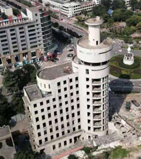
Fig. 2Surrounding environment
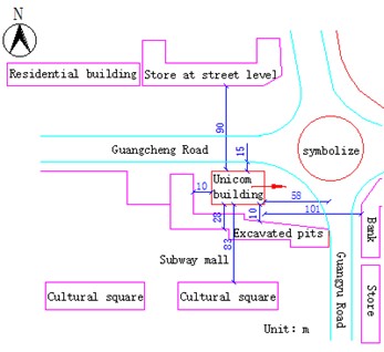
Fig. 3Front view of the union building
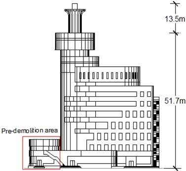
Fig. 4Side view of the union building
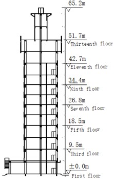
Fig. 5Floor plan of the union building
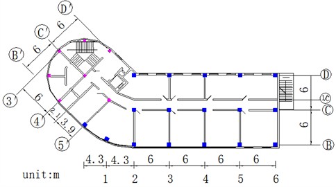
As depicted in Figs. 3-5, the building is a thirteen-story continuous multi-span frame-shear structure with dimensions of 38.5 meters in east-west length and 12 meters in north-south breadth. The main body stands at a height of 51.7 meters, while the mushroom pavilion reaches a height of 13.5 meters. The load-bearing columns have a cross-section size of 0.7 m×0.7 m and are arranged in three rows in the north-south direction and eight rows in the east-west direction. Additionally, the stairwell features a shear wall structure with a thickness of 0.2 meters. The mushroom pavilion, although nearly independent from the collapse site caused by blasting, is susceptible to forward phenomena during the collapse process, posing risks to facilities ahead of its collapse. Therefore, it is crucial to conduct research on safe and effective explosion demolition techniques to ensure safety measures are implemented effectively.
3. Mechanical characterization of building collapse instability
When the building is demolished by blasting, each cross section undergoes bending moment, shear force, and axial force that vary with the angle of rotation during the tipping process. Furthermore, even for identical cross-sections, the stresses on different parts are not uniform. Take any dumped body unit for analysis, as shown in Fig. 6.
Fig. 6Force analysis diagram of cross-section unit
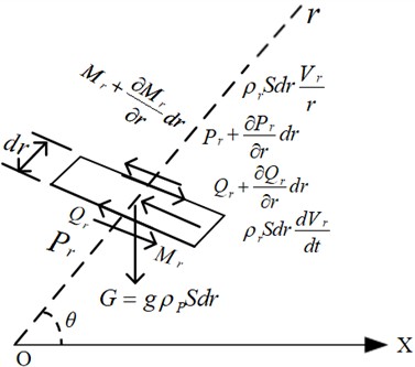
In Fig. 6, air forces are neglected, and Eq. (1-3) can be obtained from the equilibrium conditions:
where, θ is the angle of rotation of the dumped body at a certain moment; r is the distance from the center of gravity of the unit body to the pivot point of rotation; g is the acceleration of gravity; S is the cross-sectional area of the unit; Vr is the velocity of the unit.
Combining Eqs. (1-3) yields that the axial force, tangential force and bending moment applied at any position (r,θ) can be expressed as respectively:
where, L represents the total height of the tipping body, W represents the total weight of the tipping body, pr, Qr, and Mr represent the axial force, tangential force, and moment exerted on the cross-section, respectively.
By analyzing Eq. (4), it can be deduced that when θ=0 and r=0, the axial force is oriented vertically at this particular moment. By examining Eq. (5), it can be inferred that when ∂Qr/∂r=0, the maximum shear stress occurs at r=2L/3, while the maximum shear stress τmax=Q2L/3/S. Through analysis of Eq. (6), it can be concluded that when ∂Mr/∂r=0, the maximum moment arises at r=L/3. Additionally, the maximum tensile stress τmax=(ML/3-PL/3)/J, in this scenario, J represents the sectional moment of resistance.
4. Optimization of the blasting and demolition program
4.1. Program design
Different notch forms yield varying blasting effects, making it imperative to optimize the notch. Conduct a detailed analysis of the structural characteristics and aspect ratios of both the main structure and the mushroom pavilion, and determine the corresponding appropriate incision forms. By incorporating the surrounding environment of the actual project, utilize simulation calculation and monitoring techniques to finalize the incision form. The schematic diagram of the optimization algorithm process is illustrated in Fig. 7.
Fig. 7Schematic flow of the incision optimization algorithm
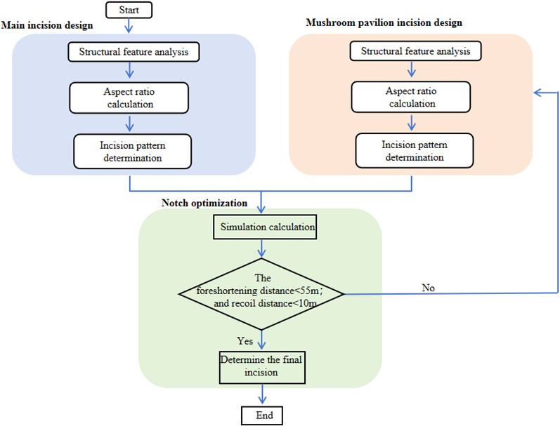
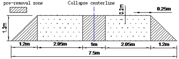
In this paper, the mushroom pavilion is a reinforced concrete cylindrical structure with a high height-to-width ratio. A trapezoidal notch is typically employed to ensure precise orientation. The lower main building, on the other hand, features a cuboidal structure with smaller dimensions and utilizes a triangular notch to achieve accurate orientation while facilitating blasting operations. Single-notch and double-notch blasting demolition forms were developed to investigate the effective stress change and collapse damage pattern of the building under each type of notch, respectively. As shown in Table 1, Scheme 1 aims to create a trapezoidal notch in the upper part of the mushroom pavilion and a triangular blasting notch in the lower part of the main building (Fig. 8). Fig. 9 illustrates the configurations for the positive trapezoidal notch hole for the Mushroom Pavilion. Scheme 2 aims to open a triangular blasting notch in the lower part of the main building while leaving the upper part of the mushroom pavilion without any notches.
Table 1Experimental design scheme
Form of notch | Mushroom pavilion upper notch | Lower main floor notch | |
Scheme 1 | double notch | trapezoidal | triangles |
Scheme 2 | single notch | no notch | triangles |
Fig. 8Schematic diagram of the building notch
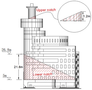
Fig. 9Trapezoidal notch unfolding of mushroom pavilion
4.2. Model parameters
The load-bearing members of this continuous multi-span building structure consist of beams, columns, and shear walls. The non-load-bearing members such as infill walls and floor slabs are equated with the load-bearing members to establish a monolithic model. In order to ensure accurate calculations and convergence, the SOLID164 ortho-hexahedral element is selected with increased mesh density (a total of 31,372,527 nodes and 2,234,742 elements in this model). The author has performed a finite element simulation calculation using MAT124 (the tensile-compression elastic-plastic material model) and found that the model can simulate the mechanical properties of concrete materials under a variety of circumferential pressure conditions, including uniaxial tension, uniaxial compression, triaxial compression, and different circumferential pressure conditions. It also has the advantage of being independent of the unit size effect, which can make it better applied to the numerical calculation of demolition of concrete-like building structures [16]. Therefore, the beams and columns adopt MAT124 to accurately determine the model parameters under hoop constraints [17].
In this model, the density of the columns is 2400 kg/m3, with a Young’s modulus of elasticity of 30.98 GPa, a Poisson’s ratio of 0.20, and a failure strain of 0.01. Similarly, the beams possess a density of 2400 kg/m3, a Young’s modulus of elasticity of 30.91 GPa, a Poisson’s ratio of 0.20, and a failure strain of 0.01. To accurately capture the mechanical properties of the materials, MAT124 necessitates the definition of separate uniaxial complete stress-strain curves for each material. The uniaxial complete stress-strain curves for the columns and beams are illustrated in Figs. 10-11, respectively. The shear walls are modeled using MAT3 (*MAT_PLASTIC_KINEMATIC) with parameter values shown in Table 2.
Fig. 10The complete stress-strain curve of column under uniaxial action
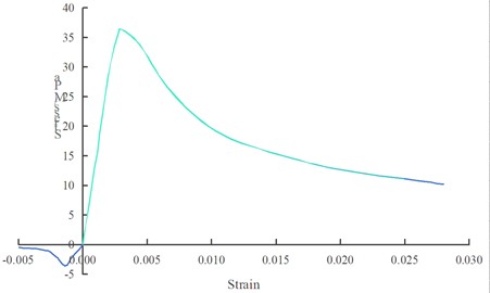
Fig. 11The complete stress-strain curve of beam under uniaxial action
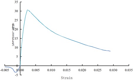
Table 2Shear wall parameters (*MAT_PLASTIC_KINEMATIC)
Densities | Young’s modulus of elasticity | Poisson’s ratio | Yield stress |
2500 Kg/m3 | 30GPa | 0.2 | 30MPa |
4.3. Blasting partitioning
In Scheme 1, MS2 detonators were utilized to fill the mushroom pavilion hole, and the upper notch exploded 1975 ms ahead of the lower notch (with a 25 ms extension delay). As depicted in Figs. 12-13, the lower notch is segmented into four zones of detonation: the first zone, which has a half-second extension of five paragraphs; the second zone, which has a half-second extension of six paragraphs; the third zone, which has a half-second extension of seven paragraphs; the fourth zone, which has an eight paragraph extension; and the fifth zone, which has a half-second extension of nine paragraphs. In Scheme 2, no detonation occurred in the upper notch while zoning was applied to the lower notch with time difference settings consistent with those in Scheme 1. The specific time difference settings are detailed in Table 3.
Fig. 12Plan view of the notch partition in Scheme 1
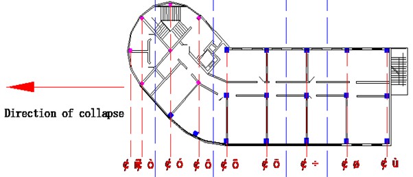
Fig. 13Elevation of the notch partition in Scheme 1
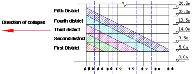
Table 3Statistics on time difference settings
Scheme 1 | Scheme 2 | ||
Upper notch | Partition-less | MS2 | / |
Lower notch | The first zone | HS5 | HS5 |
The second zone | HS6 | HS6 | |
The third zone | HS7 | HS7 | |
The fourth zone | HS8 | HS8 | |
The fifth zone | HS9 | HS9 | |
Note: MS denotes a millisecond delay; HS denotes a half-second delay | |||
4.4. Model building
In this paper, zonal segmentation of the explosion is achieved by utilizing * MAT_ADD_ERISION and * CONTACT_ERODING_SINGLE_SURFACE to define the contact relationship between the building and the ground, as well as * LOAD_BODY_Y to achieve gravity loading. Fig. 14 illustrates the final numerical calculation simulation model of the building. During the modeling process, the enclosure structure between the main body and the mushroom pavilion is correspondingly simplified.
4.5. Comparison of calculations
4.5.1. Change in vertical displacement
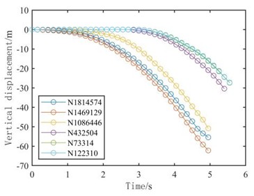
Measurements were taken at various nodes in two different schemes to investigate the vertical displacement of the building during its collapse. Nodes N1814547 and N1469129 were selected on the left and right sides of the top of the mushroom pavilion, node N1086446 was chosen on the left side of the supporting part at the bottom of the mushroom pavilion, node N432504 was identified on the right side of the top of the semicircular frame of the main body part, and nodes N73314 and N122310 were located on the right side of the top of the main body frame, as depicted in Fig. 15(a).
Fig. 14Numerical model of the Union Building
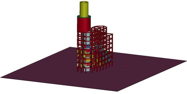
Fig. 15Schematic diagram of vertical displacement of measurement points
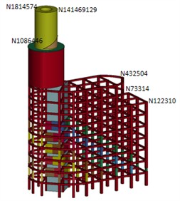
a) Measurement point arrangement
b) Scheme 1
c) Scheme 2
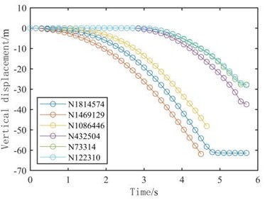
As illustrated in Fig. 15(b), Scheme 1 exhibits a stable tendency to collapse after approximately 1 second. This is evidenced by the gradual acceleration of vertical displacement in the mushroom pavilion notch following its formation. The acceleration of vertical displacement steadily increased after 3 seconds, leading to the establishment of a stable collapse trend once all notches at the bottom of the main section had formed.
As depicted in Fig. 15 (c), Scheme 2 displayed a stable collapse trend emerging after around 1.5 seconds, with a progressive increase in vertical displacement acceleration of the mushroom pavilion following the development of the bottom notch. A stable collapse tendency was observed after 3.5 seconds, as vertical displacement acceleration progressively increased upon the creation of all bottom notches in the main section.
Comparative analysis indicates that the bidirectional notch shape portrayed in Scheme 1 can expedite the formation of a stable collapse trend between the mushroom pavilion and the main body, thereby enhancing building disintegration during the collapse.
The horizontal displacement time-range curves of nodes N122310 and N1814547 were extracted to further investigate the forward and recoil phenomena during the building collapse under the two scenarios, as depicted in Fig. 16.
Fig. 16The horizontal displacement time-range curves of nodes N122310 and N1814547
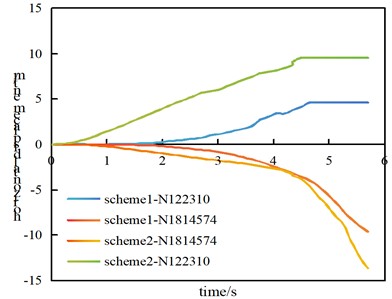
The foreshortening and recoil distances generated by the key nodes in Fig. 16 are extracted, as presented in Table 4.
The results from Fig. 16 and Table 4 demonstrate that in Scheme 1, the forward distance during the building collapse is measured at 9.5 m with a recoil distance of 4.6 m. In Scheme 2, the forward distance reaches 13.2 m while the recoil distance extends to 9.8 m. Upon comparison, it can be observed that both the forward and recoil distances achieved by Option 1’s double-cut approach can achieve the requirements of the project site, resulting in an improved blasting effect.
Table 4Comparison of blasting effects of two schemes
The forward distance / m | The recoil distance / m | Effects of blasting | |
Scheme 1 | 9.5 | 4.6 | Preferably |
Scheme 2 | 13.2 | 9.8 | The military fiber optic cable is susceptible to easy disruption, and the explosive pile can easily disperse into the pit |
4.5.2. Change in stress distribution
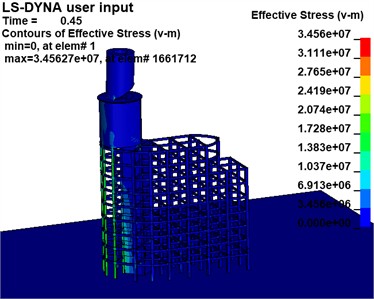
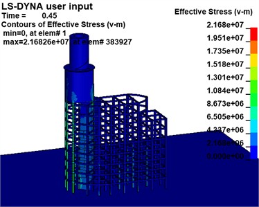
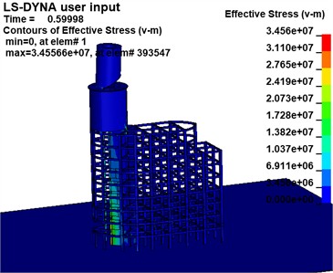
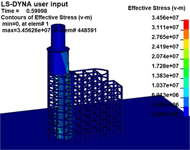
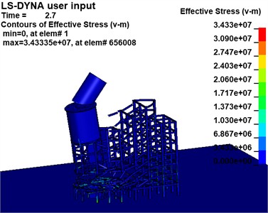
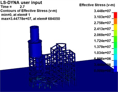
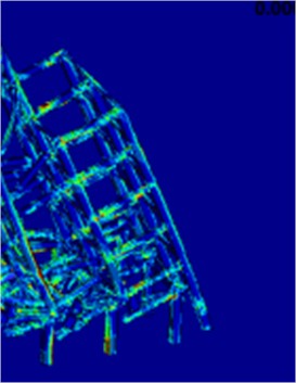
The effective stress variations of the building at the critical moment in the two Schemes are extracted, as illustrated in Fig. 17, to examine the motion pattern of the destabilized collapse of the building following the development of the notch.
Scheme 1 demonstrates that the support reaction force of the mushroom pavilion is transferred to the left column of the main section when a higher notch is created due to gravity. The column adjacent to the root of the notch suffers severe injury and deformation after the formation of the lower 1-zone notch. As subsequent sections of the notch form, the column at the root gradually shifts from left to right and sustains increasing damage.
Fig. 17Effective stress cloud map
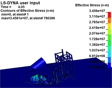
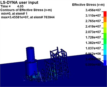
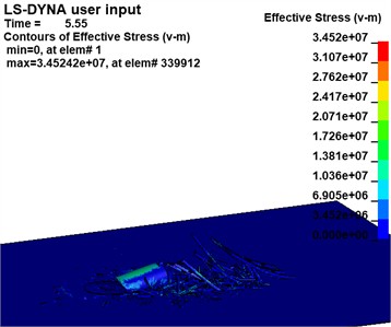
a) Scheme 1 (unit: Pa)
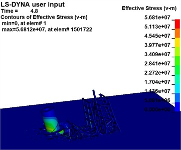
b) Scheme 2 (unit:Pa)
Simultaneously, noticeable bending and deformation occur in the upper portion of the rear row of beams and columns. The rear row experiences demolition in a top-to-bottom manner as the structure collapses. Scheme 2, demonstrates a similar process of deformation and destruction when compared to Scenario 1, but with more obvious bending deformation in the lower beams of the rear row. Furthermore, as collapse progresses, damage to beams and columns gradually shifts backward; lower beams and columns sustain initial damage with less overall bending deformation.
4.6. Determination of the blasting scheme
Based on the aforementioned comparative analysis, Scheme 1 can expedite the formation of a stable collapse trend between the mushroom pavilion and the main body, regulate the landing position of the mushroom pavilion, and facilitate the degree of disintegration upon collision with the building, resulting in an effective blasting effect. The actual blasting construction is represented by a bidirectional notch scheme. Tables 5-6 present the notch blasting parameters for the main body and mushroom pavilion, respectively.
Table 5Summary of blasting parameters for load-bearing components of the main building
Borehole site | Borehole spacing/mm | Row spacing/mm | Depth of hole/mm | Unit consumption of explosives / (g∙m-3) | Charge of single hole/g | Charging structure |
Column 550×550 | 300 | / | 380 | 1800 | 166 | Individual packets |
Column 750×750 | 300 | 300 | 500 (single) | 1800 | 300 (single) | 1 (single) |
550 (double) | 150 (double) | 2 (double) | ||||
Column 650×700 | 300 | 250 | 480 (single) | 180 | 250 (single) | 1 (single) |
530 (double) | 125 (double) | 2 (double) | ||||
Shear wall (200) | 200 | 200 | 150 | 3750 | 30 | 1 |
Table 6Statistics of blasting parameters of mushroom pavilion
Forms of hole arrangement | Drilling diameter / mm | Depth of hole / cm | Borehole spacing / mm | Row spacing / mm | Unit consumption of explosives (g∙m-3) | Charge of single hole / g |
Plum blossom type | 36 | 16 | 250 | 200 | 2400 | 40 |
5. Structural collapse instability motion and internal force analysis
5.1. The actual collapse of the building
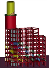
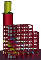
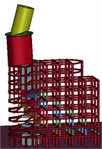
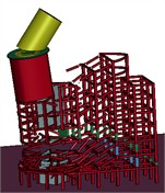
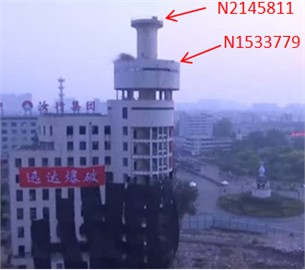
The actual blasting and demolition of the Unicom building, as well as the numerical computation of the collapse process, are illustrated in Fig. 18 through Scheme 1. To further validate the accuracy of the simulation calculation model, the vertical coordinates (Table 7) corresponding to nodes N2145811 and N1533779 (Fig. 19) from both the simulation calculation model and the actual collapse process of the building were extracted at t=0.3 s, t= 1.9 s, and t= 2.8 s respectively.
Fig. 18Actual collapse process and numerical calculation of collapse process of demolition of Unicom building

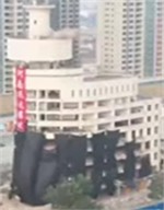
a)t=0 s
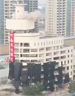
b)t=0.15 s
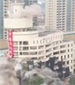
c)t=2.5 s
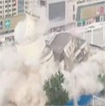
d)t=4.0 s

e)t=4.5 s
As depicted in Fig. 18, at t=0 s, the mushroom pavilion blasting notch forms, and the material in the notch zone is removed from the model. The mushroom pavilion superstructure then directly acts on the area of retained support. By t=0.15 s, a consistent propensity for collapse has developed within the mushroom pavilion. This trend stabilizes by t=2.5 s, with a stable collapse established in the main part of the building. At t= 4.0 s, sufficient deformation disintegration occurs in the main part of the building, followed by further collapses and deformations at t=4.5 s. The accuracy of the calculation model is validated by its strong consistency with the actual collapse process of the building throughout the numerical calculations.
Table 7Vertical coordinates of key nodes at different moments
Simulation vertical coordinate / m | Measured vertical coordinates / m | Error | ||
N2145811 | t= 0.3 s | 65.20 | 64.95 | –0.38 % |
t=1.9 s | 59.15 | 58.96 | –0.32 % | |
t=2.8 s | 47.91 | 48.71 | 1.7 % | |
N1533779 | t= 0.3 s | 51.88 | 51.70 | –0.35 % |
t=1.9 s | 46.25 | 46.71 | 1 % | |
t=2.8 s | 33.82 | 34.70 | 2.6 % | |
As depicted in Table 7, The error between the simulation calculation and the measured vertical coordinates of node N2145811 during the building collapse process is –0.38 % at t=0.3 s, –0.32 % at t=1.9 s, and 1.7 % at t=2.8 s; for node N1533779, it is –0.35 % at t=0.3 s, 1 % at t=1.9 s, and 2.6 % at t=2.8 s respectively. The numerical calculation process demonstrates strong consistency with the actual collapse process of the building, thereby verifying the correctness and accuracy of the calculation model.
Fig. 19Schematic diagram of the location of key measurement points
5.2. Blasting effect
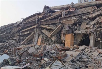
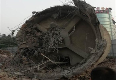
The demolition of this project utilizes the notch form depicted in Scheme 1 for blasting purposes. Following detonation, the Mushroom Pavilion collapsed towards the west initially, and after a delay of 0.5 seconds, the main building sequentially collapsed towards the east. Post-collapse, the maximum height of the debris pile reached 3 meters, while it remained at a distance of 15 meters from the military fiber-optic cable. Notably, there was no rolling down of the mushroom pavilion towards the south side of the deep foundation pit; moreover, effective control measures ensured that flying rocks were contained within manageable boundaries during the building collapse. The configuration of the debris pile is illustrated in Fig. 20.
Fig. 20The pattern of bursting
a) The prevailing bursting pattern
b) The mushroom pavilionbursting bursting pattern
5.3. Variation of internal forces in beams and columns
5.3.1. Program design
The following principles govern the numbering of beams and columns in the structure to facilitate the analysis of deformation damage and changes in internal forces of beams and columns in various parts of the building during the collapse process:
Beam: The beam is numbered according to the floor (construction type), column axis, column interval, beam end location, and symbol for internal force. For example, 1L-6-BC-B-M indicates the bending moment at the end of the BC beam on the 6th longitudinal axis near end B on the 1st floor.
Column: The column can be identified using both transverse axis and longitudinal axis numbers. For example, “The 6th B-axis column” refers to a column where the sixth vertical axis intersects with the sixth horizontal axis.
5.3.2. Determination of damage location
The motion pattern of the building collapse suggests that, during the structural collapse, there was a top-to-bottom damage phenomenon experienced by the back row of beams and columns. The rear row of columns (3L-6-B, 5L-6-B, 7L-6-B, 3L-6-C, 5L-6-C, 7L-6-C), the rear row of beams, and the lateral side beams (3L-6-BC, 5L-6 BC, 7L-6-BC, 3L-B-56, 5L-B-56, and 7LB-56) were examined to further study the changes in internal forces. This is illustrated in Fig. 21.
Fig. 21Schematic diagram of damage location
5.3.3. Changes in internal forces of beams and columns in key parts
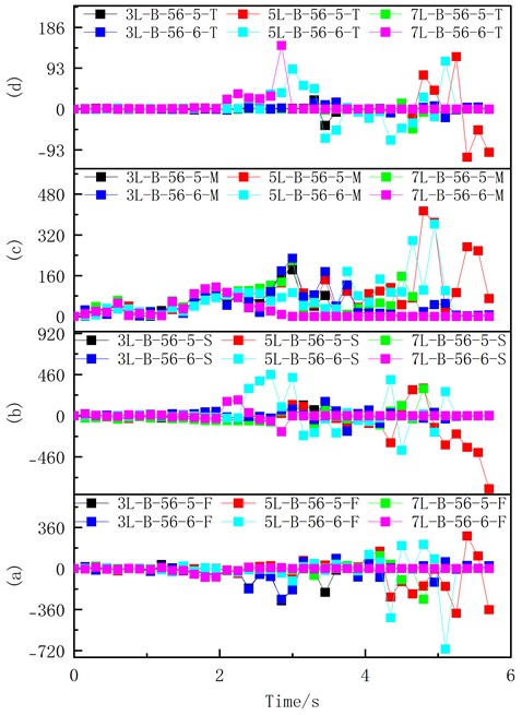
As illustrated in Figs. 22-23, the axial force, shear force, bending moment, and torque were determined at the ends and midpoints of both sides of the damaged beams and columns in the main component. (Axial force is designated as positive for tension and negative for compression. For shear force, a positive value is assigned when it causes the left portion of the cross-section to rise and the right portion to descend, with the opposite direction indicating a negative shear force. Regarding bending moments, a positive sign is given when the lower part of the cross-section experiences tension, and conversely, a negative sign is applied when the upper part is in tension. Applying the right-hand helix rule, if the thumb points towards the outer normal of the cross-section and the torque rotates in the same direction as the grip formed by the four fingers, the torque is considered positive; otherwise, it is negative).
The rear row of columns experienced four periodic adjustments in axial force following the formation of the upper notch, as depicted in Fig. 22. The overall axial force reached its peak at t=3 s after the formation of the lower notch, showing a gradual decrease from low to high. Throughout the building collapse process, the shear pressures on the back upper and lower columns were stronger than those on the center columns and acted in opposite directions. Furthermore, the bending moment exhibited distinct characteristics with the lowest bending moment occurring in the middle part, followed by the upper section, and then by the highest value in the lower section; however, there were no significant variations in torque overall. This indicates severe damage to both upper and lower columns, with evidence of bending and shear damage throughout all rear columns.
Fig. 22Variation of internal force in the column of main body damage: a) depicts axial force (kN); b) represents shear force (kN); c) displays bending moment (kN·m); d) portrays bending moment (kN·m)
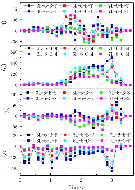
Fig. 23 illustrates the increased axial pressure experienced by the middle and lower beams, as well as the greater axial tension experienced by the upper beams following the development of the notch. The center beam exhibits the largest C-axis cross-section shear force, while the lower rear beam experiences the greatest bending moment. Additionally, it is observed that the rear center beam has the biggest C-axis cross-section torque. These findings suggest that there was some twisting distortion that occurred when the structure collapsed, with the middle and lower beams suffering from significant compressive shear damage and the top beams experiencing substantial tensile damage.
The comprehensive analysis of the aforementioned can be found in Scheme I, which demonstrates a bidirectional incision form. During the process of building collapse, the rear row of columns exhibited collective bending shear damage, while severe damage was observed in both upper and lower columns. Tensile damage primarily occurred in the upper beam, whereas pressure shear damage mainly affected the middle and lower beams. Additionally, a certain degree of distortion and deformation was also observed throughout the structure. By implementing a bidirectional incision control of the landing position of the mushroom pavilion, it effectively reduced explosive pile length and provided effective protection for military fiber-optic cables located at its front to achieve precise blast control. Furthermore, due to challenges faced during demolition and blasting processes such as conducting prototype monitoring tests on large continuous multi-span structures or carrying out full-area dynamic monitoring of overall structural stress; this study utilizes simulation calculations to conduct real-time monitoring of structural collapse processes and mechanical changes. This approach enables further investigation into dynamic internal force variations within critical parts during collapse processes relative to instability and collapse phenomena documented in Literature 1 to Literature 3.
Fig. 23Variation of the internal force of the main broken beam: a) depicts axial force (kN); b) represents shear force (kN); c) displays bending moment (kN·m); d) portrays bending moment (kN·m)
6. Conclusions
In conjunction with theoretical analysis and numerical simulation monitoring, the following conclusions are drawn based on the practical experience of the blasting and demolition project of Ruzhou Unicom Building:
1) The maximum axial force occurs when the building is not deflected; the maximum shear stress appears at 2/3 of the building height where the first-order derivative of the shear force is zero; and the maximum bending moment occurs at 1/3 of the building height where the first-order derivative of the bending moment is zero. When there is no notch in the mushroom pavilion, the forward impulse phenomenon tends to occur during collapse. However, implementing a bidirectional notch design effectively prevents forward impulse problems and reduces explosion pile volume, thereby providing better protection for front appurtenant facilities.
2) During the collapse process of the main building, bending shear damage primarily occurs in the back row of columns, with particularly severe damage observed in both the upper and lower parts of these columns. Tensile damage mainly affects the upper beams, while compression shear damage predominantly affects the central and lower beams. Additionally, some distortion and deformation are also evident throughout.
3) The bidirectional notch configuration results in a forward distance of 9.5 meters and a recoil distance of 4.6 meters, providing adequate protection for the military fiber-optic cables in the front and the deep excavation pits on the sides. Furthermore, it also facilitates the rapid establishment of a stable collapse pattern between the mushroom-shaped structure and the main body, ultimately intensifying the disintegration of the building during the collapse process.
4) With the implementation of the national “urban renewal” strategy, simulation computing technology can optimize the design scheme to achieve more efficient resource utilization. High-precision simulation technology will be employed in building demolition for controlled blasting and expanded demolition range.
References
-
X. Yao et al., “Directional blasting demolition of a high rise buiding with a frame-shear structure,” Explosive Materials, Vol. 48, No. 3, pp. 49–57, 2019.
-
Z. X. Yan, P. L. Liu, and Z. H. Ye, “Directional blast collapse process of frame shear wall structure,” Explosion and Shock Waves, Vol. 31, No. 6, pp. 647–652, 2011.
-
D. Y. Yu et al., “Reinforced concrete structure based on separated co-junction model numerical simulation of demolition by blasting,” Explosion and Shock Waves, Vol. 31, No. 4, pp. 349–344, 2011.
-
S. L. Li et al., “Numerical simulation of single concrete framework implosion demolition,” Transactions of Beijing institute of technology, Vol. 32, No. 4, pp. 354–358, 2012.
-
Y.-S. Jia et al., “Efficient blasting demolition of frame-shear structure buildings in Mountain City,” Blasting, Vol. 41, No. 1, pp. 98–105, 2024.
-
W.-L. Gao et al., “Study on blasting demolition effect of frame-shear wal1 structure under influence of incision height and delay time,” Blasting, Vol. 41, No. 2, pp. 130–138, 2024.
-
J.-X. Llu, P. F. Gao, and G. Ma, “Demolition blasting and numerical simulation analysis of 18 storeyframe barrel structure building,” Engineering Blasting, Vol. 30, No. 3, pp. 74–81, 2024.
-
H.-L. Fei et al., “Numerical simulation study on folding blasting demolition of frame-tube building,” Blasting, Vol. 40, No. 3, pp. 134–142, 2023.
-
Y. S. Jla et al., “Discussion on key technology of demolishing buildings by longitudinal span – by – span collapse,” Blasting, Vol. 39, No. 4, pp. 10–16, 2022.
-
J. Ruan and D. Sheng, “Prediction model of demolition stack for high-rise buildings under extremely close protection conditions,” Iranian Journal of Science and Technology, Transactions of Civil Engineering, Vol. 47, No. 5, pp. 2639–2647, Mar. 2023, https://doi.org/10.1007/s40996-023-01084-z
-
F. Y. Luo, J. J. Yan, and C. M. Liu, “Vibration reduction and disintegration optimization of building blasting demolition,” Engineering Blasting, Vol. 28, No. 4, pp. 56–61, 2022, https://doi.org/1006-7051(2022)04-0056-06
-
S. L. Tian et al., “Numerical simulation of backward collapse in blasting demolition of 8-storey frame building,” Engineering Blasting, Vol. 25, No. 1, pp. 13–18, 2019.
-
C. Pany, “An insight on the estimation of wave propagation constants in an orthogonal grid of a simple line-supported periodic plate using a finite element mathematical model,” Frontiers in Mechanical Engineering, Vol. 8, Jul. 2022, https://doi.org/10.3389/fmech.2022.926559
-
C. Pany, S. Parthan, and M. Mukhopadhyay, “Wave propagation in orthogonally supported periodic curved panels,” Journal of Engineering Mechanics, Vol. 129, No. 3, pp. 342–349, Mar. 2003, https://doi.org/10.1061/(asce)0733-9399(2003)129:3(342)
-
C. Pany, S. Parthan, and S. Mukherjee, “Vibration analysis of multi-supported curved panel using the periodic structure approach,” International Journal of Mechanical Sciences, Vol. 44, No. 2, pp. 269–285, Feb. 2002, https://doi.org/10.1016/s0020-7403(01)00099-6
-
H. Jia and Q. Song, “The analysis of the destabilizing motion of a hyperbolic cooling tower during demolition blasting,” Journal of Measurements in Engineering, Vol. 11, No. 4, pp. 482–495, Dec. 2023, https://doi.org/10.21595/jme.2023.23470
-
H. Jia and S. Tian, “research and application of a reinforced concrete simplified model,” Advances in Civil Engineering, Vol. 2021, p. 8861831, Feb. 2021, https://doi.org/10.1155/2021/8861831
About this article
This work was supported by the Henan Province science and technology research project (242102320010), and the Henan Province housing and urban and rural construction science and technology plan project (HNJS-2022-K3).
The datasets generated during and/or analyzed during the current study are available from the corresponding author on reasonable request.
Haipeng Jia: conceptualization, data curation, formal analysis, investigation, methodology, project administration, supervision, validation, visualization, writing-original draft preparation, writing-review and editing. Yuxia Zhao: data curation, formal analysis, methodology, supervision. Tong Shen: project administration, visualization. Qianqian Song: Validation, writing-original draft preparation, writing-review and editing.
The authors declare that they have no conflict of interest.

