Abstract
With the rapid and large-scale development of urban rail transit in China, the operational safety of urban rail vehicles is highly concerned. The axle-box bearing, as the core component of vehicle bogies, directly determines the operational safety and quality of vehicles. To ensure the service performance of axle-box bearings, their fault characteristics should be monitored and diagnosed in time. A more realistic and in-depth understanding of fault characteristics is a prerequisite for fault diagnosis. Thus, a double-rows tapered roller bearing (DTRB)-vehicle-track coupled dynamic model was built via the co-simulation in this paper, which comprehensively considers a DTRB model with the localised outer ring raceway fault, as well as the flexibilities of the wheelset, axle-box, and bogie frame. Its correctness and rationality were verified by the theoretical comparison and the field test. The results indicate that the distribution of contact load is consistent with the theoretical value, the fault features of the outer ring raceway can be found in the periodic impulse of the roller-raceway contact load. The slip rates of rolling elements are less than 4.3 %. Compared with the field test, the fault order harmonics in the order spectrum of the simulation are closer to the theoretical fault characteristic order under variable and constant speed conditions, and the maximum error is only 0.37 %. Therefore, the proposed coupled dynamic is correct and can be employed to investigate the fault characteristics of axle-box bearings in urban rail vehicles.
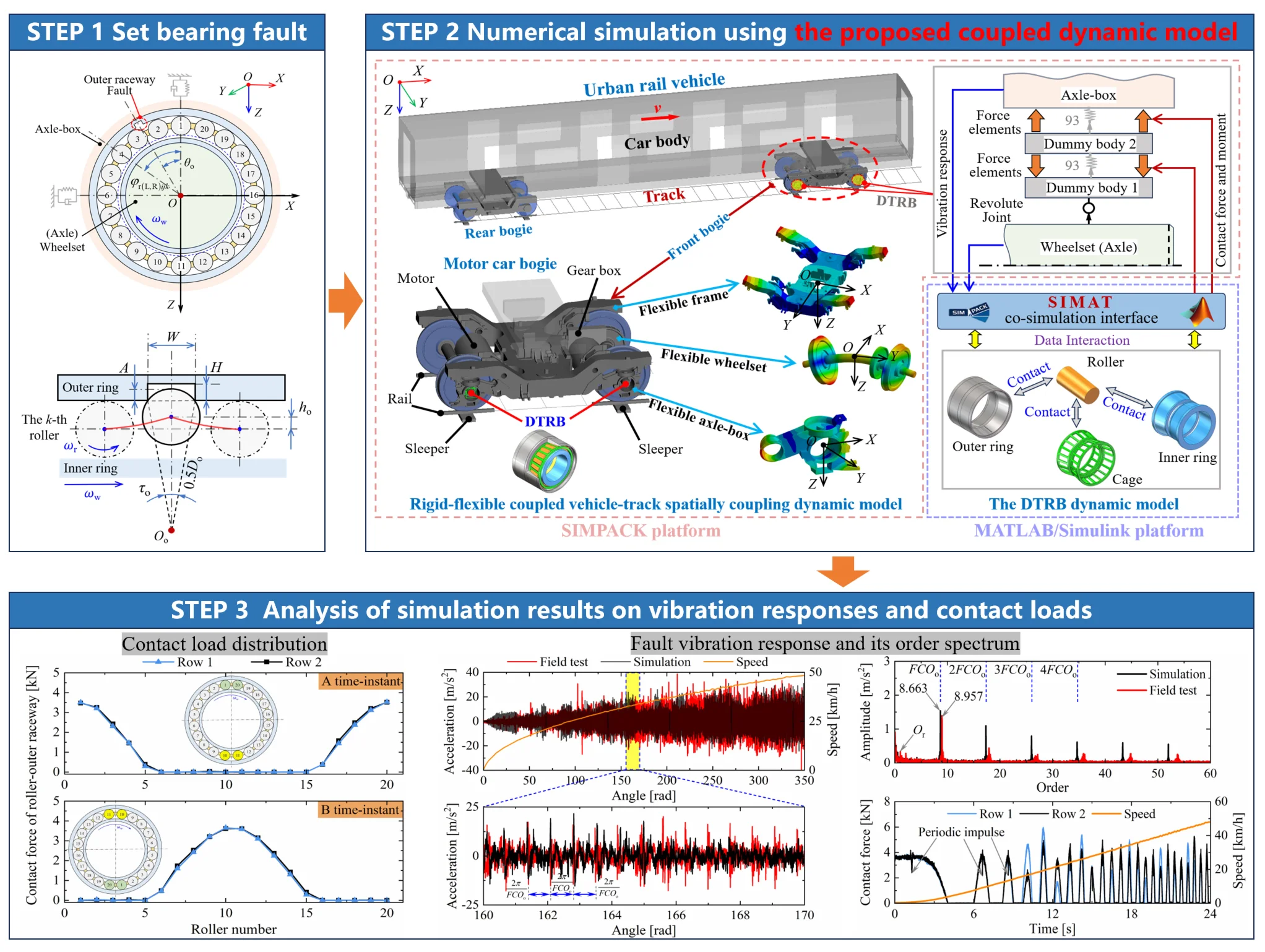
Highlights
- Comprehensive simulation model: this study successfully developed a double-rows tapered roller bearing (DTRB)-vehicle-track coupled dynamic model via the co-simulation for studying the outer ring fault characteristics and mechanisms of axle-box bearings.
- Accurate simulation results: the fault order harmonics in the order spectrum of the simulation closely match the theoretical fault characteristic order under variable and constant speed conditions, and the maximum error is only 0.37%.
- Wide application prospects: The proposed coupled model can be used to analyze and reveal the fault characteristics of axle-box bearings in urban rail vehicles. Additionally, it can provide a feasible theoretical basis for the research of fault diagnosis algorithms and life assessment.
1. Introduction
In recent years, urban rail transit has experienced rapid development and grown in large-scale to meet the demand of urbanization in China [1]. The urban rail transit train, as the transport tool, is one of the core components of the urban rail transit system. The axle-box bearing is the critical subcomponent of the vehicle bogie in urban rail transit trains. It is installed inside the axle-box housing, and plays a pivotal role in motion transformation and load transmission during vehicle operation [2]. Its performance directly determines the operational safety and quality of urban rail transit trains. However, urban rail transit trains need to start and stop frequently to deliver passengers in short station intervals. Long-term variable speed operating result in the cyclic alternating load conditions. These load conditions are prone to hasten and cause fatigue failure of axle-box bearings, so as to endanger the operational safety of urban rail transit trains. To ensure the service performance of the axle-box bearing, it is necessary to deeply understand the fault characteristics and mechanisms, as well as contact load characteristics to provide a reliable theoretical basis for its fault diagnosis based on vibration signals, and remaining life assessment based on contact features [3]-[5]. Therefore, a corresponding coupled dynamic model involving axle-box bearings and considering the real operating conditions of urban rail vehicles is urgently needed.
The double-rows tapered roller bearing (DTRB) is widely adopted in the axle-box bearings of urban rail transit trains due to its excellent radial and axial loading capacity. Therefore, to establish this coupled dynamic model more realistically, on the one hand, the DTRB dynamic model considering variable speed conditions and localised surface fault should be employed, rather than lumped-parameter models, quasistatic models, quasi-dynamic models, and finite element models [6]. The reason is that the later models either cannot reveal the motion process and internal dynamic interaction relationships between bearing rolling elements, or need high computational costs and making it difficult to implement coupling analysis [7]. On the other hand, the coupling effects among axle-box bearings, the vehicle, and the track must be considered, because the track irregularity and wheelset faults of the vehicle have a significant influence on the load distribution of axle-box bearings [8]. Moreover, the high-frequency flexible deformation and vibration of vehicle components induced by wheel-rail excitation and axle-box bearing faults should be considered. Based on the above-mentioned prerequisites, several DTRB-vehicle-track coupled dynamic models of high-speed trains considering track irregularity, wheelset faults, bearing faults, and the flexibility of wheelsets, axle-boxes, and gearboxes had been successively established [9]-[13]. The vibration response of the axle-box and the internal contact load characteristics of axle-box bearings under multisource fault conditions were obtained and analysed by these models. However, these models are modelled for high-speed trains, they only consider constant speed operating conditions, and the bogie frame was modelled as a rigid body. In practice, vehicle components are not strictly rigid bodies, they inevitably undergo elastic deformation and vibration under external random excitations. This deformation and vibration further influence the internal contact characteristics of axle-box bearings [14]. Naturally, the coupling effect of flexible vibration for the bogie frame in the vehicle dynamic model should also be considered. Furthermore, urban rail vehicles often need to change running speed frequently, so the vibration response and dynamic contact behaviours of the axle-box bearing under variable speed conditions need to be paid more attention.
Consequently, this paper aims to develop a comprehensive coupled dynamic model of urban rail vehicles to study the vibration and contact load characteristics of faulty axle-box bearings under variable speed conditions. This model integrates an urban rail vehicle-track coupling dynamics model and the DTRB dynamic model. Thereinto, the wheelset, axle-box, and bogie frame of vehicle dynamics model are modelled as flexible components. In the DTRB model, the outer ring raceway fault is set to simulate the axle-box bearing fault. By the established coupled model, the contact load and vibration response of the axle-box bearings using the DTRB can be obtained. The theoretical contact load is compared with the simulation results to verify the correctness of the DTRB model. The motion process, load distribution, and slip rate are analysed to demonstrate rationality. The field tests under variable and constant speed conditions are carried out, and the vibration acceleration of the axle-box is compared and analysed to validate the correctness and feasibility of the proposed coupled model.
This paper is organized as follows: Section 2 elaborates on the theoretical derivation and implementation of dynamic modelling for the rigid-flexible coupled DTRB-vehicle-track spatial coupling system considering the outer ring raceway localised fault. Then, the theoretical comparison and the field tests are conducted to validate the correctness and the rationality of the proposed model in Section 3. Finally, conclusions are drawn in Section 4.
2. Dynamic modelling of the DTRB-vehicle-track coupling system considering the outer ring fault
As shown in Fig. 1, the proposed DTRB-vehicle-track spatially coupling dynamic model in this paper comprises four subsystems [13], [15]: the vehicle, the DTRB, the wheel-rail contact, and the track. The interaction of the vehicle and the track is characterised by the wheel-rail in rolling contact. The DTRB is located in the axle-box housing of the vehicle, and its outer ring and inner ring are installed in the axle-box and axle end of the wheelset by the interference-fit connection method, respectively. In the vehicle model, a car body, two bogie frames, four wheelsets, four gearboxes, and eight axle-boxes are considered. The car body is supported and connected on two bogie frames through secondary suspensions. The bogie frame and the wheelset are connected by the primary suspensions. The primary suspensions and the secondary suspensions are represented using 3D spring-damper elements. In the track model, the interaction from rails to sleepers and the interaction from sleepers to ballasts are equivalent to the interaction from rails and ballasts. Each rail is supported and connected with ballasts by the distributed stiffness and damping, and each ballast is connected with the roadbed (i.e., the ground) via the same force element. Dynamic modelling of DTRB with the outer ring raceway fault in the proposed model is described in subsection 2.1. Thereafter, the DTRB-vehicle-track coupling dynamic model considering the flexibility of vehicle component is given in subsection 2.2. The degrees of freedom (DOFs) considered in our DTRB-vehicle-track coupling dynamic model are listed in Table 1. The modelling details are as follows.
Fig. 1Schematics of the dynamic model of DTRB-vehicle-track spatial coupling system
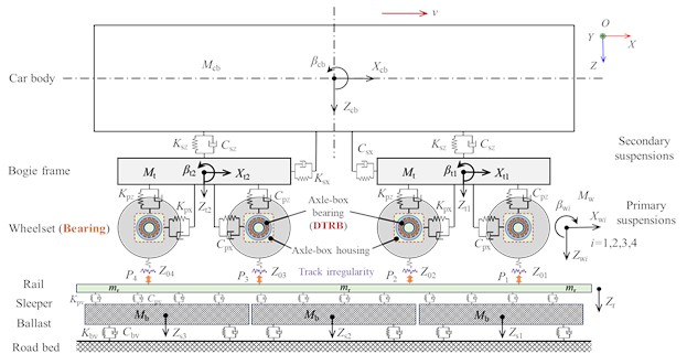
a) Side view
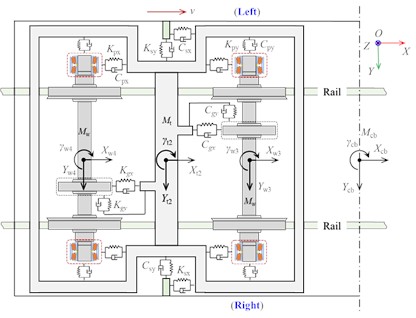
b) Top view
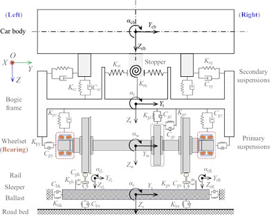
c) End view
2.1. Dynamic modelling of DTRB with the outer ring raceway fault
A DTRB using a back-to-back arrangement is adopted for axle-box bearing, as shown in Fig. 2(a) and (b). It consists of two inner rings, an outer ring, multiple rollers, two cages, and a spacer. In this paper, we assume that its outer ring and inner ring are fixed in the axle-box housing and axle end of the wheelset respectively. During operation, it undertakes the longitudinal load, the lateral load, and the vertical load generated by the secondary mass (including the bogie frame and car body), the traction (braking) action, and wheel-rail contact. Its loading process and contact force analysis are depicted in Fig. 2(c) and (d).
Table 1DOFs of the DTRB-vehicle-track coupling dynamic model
Component | Longitudinal | Lateral | Vertical | Roll | Pitch | Yaw | |
Vehicle | Car body | ||||||
Bogie frame (1-2) | |||||||
Wheelset (1-4) | |||||||
Gearbox (1-4) | – | – | |||||
Axle-box (1-4) | |||||||
DTRB | Roller (1-4, 1-2, 1-) | ||||||
Cage (1-4, 1-2) | |||||||
Track | Rail | – | – | – | |||
Ballast (Sleeper) | – | – | – | ||||
Note: The subscript represents the number of the bogie frame. The subscript represents the number of the wheelset. The subscript represents the number of DTRB rows. The subscript represents the number of each roller. is the count of single-row rollers. The subscripts “” and “” represent the left and right sides of the vehicle along the running direction respectively (seen in Fig. 1(b) and (c)) | |||||||
The force analysis of DTRB and the detailed derivation of motion equations have been provided in [16], [17]. Based on these developed DTRB models, we need to couple it with the urban rail vehicle dynamic model. Namely, the dynamic response of the wheelset and axle-box, as the external excitations, should be considered in the DTRB model. As seen in Fig. 2(c), under the vertical load from the axle-box, the relative displacement will occur between the outer ring and the inner ring, the roller is squeezed by the raceway to generate the internal contact load to balance the external load of the axle-box. The contact loads are related to elastic deformations induced by relative displacements between rollers and raceways. Therefore, to calculate the contact load, it is necessary to first analyse the relative displacement. In Fig. 2(c), the relative radial displacement of the -th roller at the azimuth angle , between the rollers and outer ring raceways, as well as between the rollers and inner ring raceways can be determined by Eq. (1) [18]:
where and represent the radial relative displacement between the roller and outer ring, as well as between the roller and inner ring respectively. , , and are the longitudinal displacements of the axle-box, the roller, and the wheelset respectively. , , and are the vertical displacements of the axle-box, the roller, and the wheelset respectively. and are the roll and yaw angles of the wheelset. is the lateral semi-span of primary suspensions. is the initial clearance [19], . is the bearing radial clearance.
Fig. 2Structural composition and schematics of the dynamic model for DTRB
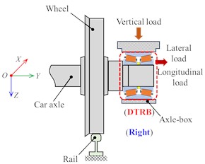
a) Schematics of axle-box bearing
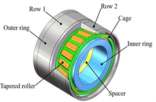
b) Structural composition of the DTRB.
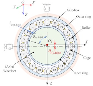
c) Schematic of loading process for DTRB
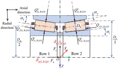
d) Contact force analysis of DTRB
Likewise, the relative axial displacement of the -th roller, between the rollers and outer rings and between the rollers and inner rings can be expressed as Eq. (2):
where and represent the axial relative displacement between the roller and outer ring, as well as between the roller and inner ring respectively. , , and are the lateral displacements of the axle-box, the roller, and the wheelset respectively. is the bearing axial clearance.
Combining Eq. (1) and Eq. (2), the elastic deformations between the roller and the outer ring raceways, as well as between the roller and the inner ring raceways can be obtained by Eq. (3):
where and represent the contact angles between the roller and the outer ring raceway, as well as the roller and the inner ring raceway respectively, as seen in Fig. 2(d).
Likewise, the elastic deformation generated by the contact between the roller and the guiding flange of the inner ring can be expressed as Eq. (4):
where represents the contact angle between the roller and the guiding flange.
Consequently, the contact load between the roller and raceways, as well as between the roller and the guiding flange in Fig. 2(d) can be obtained according to the load-deformation relationship based on the Hertzian line contact theory and the Hertzian point contact theory, they are given in Eq. (5):
where represent the contact load between the roller and raceways. represents the contact load between the roller and the guiding flange. and are the contact equivalent stiffness coefficient of the roller-raceways and the roller-guiding flange respectively, they can be calculated by [19], [20].
Furthermore, the corresponding frictional forces and additional moments caused by the above contact loads are calculated according to [16]. Simultaneously, the motion differential equations of DTRB in the proposed coupling model can be obtained, they are given in [16]. Then, the forces and moments acting on the inner ring (i.e., the wheelset) and outer ring (i.e., the axle-box) can be continuously solved at each time instant.
Fig. 3Mathematical characterisation diagram of outer ring fault for DTRB
a) Fault on the outer ring raceway
b) Local expansion of outer ring fault
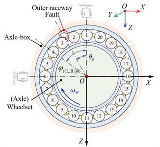
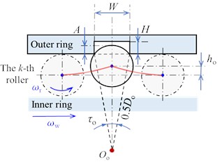
In order to study the outer ring fault characteristics and mechanisms of axle-box bearing, the localised surface fault needs to be set in the outer ring raceway of above DTRB dynamic model to simulate the bearing fault. Typically, the localised faults are characterised as additional deformations in the contact pair of bearing elements [21],[22]. As shown in Fig. 3, when the -th roller at the azimuth angle passes through the fault of length , width , and depth , the additional clearance caused by the fault can be expressed as [22]:
where is the maximum value of clearance variation, . is the radius of the roller, . is the initial offset angle between the outer ring raceway fault and the first roller, it is set to 0 in this paper. is the angle corresponding to the outer ring raceway fault, . is the diameter of the outer ring raceway (seen in Fig. 2(d)). The contact azimuth angle of the -th roller can be obtained by Eq. (7):
where is the rotation angular velocity of the cage, . is the rotation angular velocity of the wheelset. is the pitch diameter, as seen in Fig. 2(d).
Thus, in the faulty DTRB dynamic model, the elastic deformations between the roller and the outer ring raceways in Eq. (3) is redefined as follows:
Based on Eq. (8), the contact deformation and contact load between the roller and raceway will be calculated in the DTRB model with outer ring fault. And the vibration response of the faulty DTRB model can be solved.
2.2. DTRB-vehicle-track coupling dynamic model considering the flexibility of vehicle components
Based on the above theoretical foundations and vehicle-track coupled dynamics theory [23], a comprehensive simulation model of the DTRB-vehicle-track coupling dynamic model is formulated, as illustrated in Fig. 4. The simulation model integrates an urban rail vehicle-track coupling dynamic model and the faulty DTRB dynamic model. The interactions between the vehicle and the DTRB are described through the dynamic contact forces and moments of the DTRB acting on the axle-box and wheelset. Thereinto, the vehicle-track model considering the flexibilities of the bogie frame, the axle-box, and the wheelset is modelled in the SIMPACK platform. The flexibilities of these three components of the front bogie are considered only to improve computational efficiency. Their dynamic responses are obtained by modal superposition.
Fig. 4Proposed DTRB-vehicle-track coupling dynamic model considering the flexibility of vehicle components and bearing outer ring fault
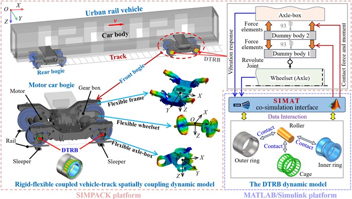
They are coupled in the dynamic model by the Guyan substructure modal reduction method [24]. The FE models of the wheelset and axle-box in the modal analysis are discretised using the Solid 185 element, and the bogie frame is mainly discretised using the Shell 181 element. Vibration modes of approximately 300 Hz, 1000 Hz, and 3000 Hz for the bogie frame, wheelset, and axle-box are considered. The profiles of the wheel tread and rail are the LM and the CHN 60. The FASTSIM algorithm is used to solve wheel-rail contact relationships. The typical America 5-class track spectrum is employed to express the characteristics of track random irregularity excitation. The wheelset and axle-box are connected through the DTRB model, which is modelled as two dummy bodies, two time-excitation force elements (i.e., No. 93 force element in SIMPACK), and a revolute joint. Dummy body 2, as an intermediate component, is used to transmit the contact forces and moments from the SIMAT co-simulation interface to the axle-box and the wheelset via the No. 93 force element. Dummy body 1 is employed to convert motion forms through the rotation joint. Correspondingly, the dynamic model of the DTRB is established and integrated into the MATLAB/Simulink platform. The dynamic responses of the DTRB elements, and the force and moment acting on the wheelset and axle-box are calculated and solved according to the preliminaries in Subsection 2.1 and the developed DTRB dynamic model in [16], respectively. The solution results are subsequently applied to the axle-box and the wheelset of the vehicle dynamic model via the SIMAT co-simulation interface to investigate the dynamic responses of the proposed coupling dynamic system. Simultaneously, the vibration responses of the axle-box and wheelset are fed back to the DTRB model through the co-simulation interface. This process is iterated at the next time step until the simulation is complete.
3. Verification and discussion of the proposed coupled dynamics model
To verify the correctness of the DTRB model in the proposed model, the contact load of the normal DTRB model is compared with the theoretical load distribution. The periodicity of contact load for the faulty DTRB model is analysed to demonstrate the feasibility of studying fault characteristics. The rationality of the instantaneous contact load movement process and the slip rate are discussed and analysed. To verify the correctness and effectiveness of the proposed coupling model, the vertical acceleration of the axle-box bearing with outer ring fault is measured in the field test and is compared with the simulation result of the proposed model. Because urban rail vehicles usually operate at variable speeds between two stations, the traditional envelope analysis method will be no longer applicable due to frequency distortion occurring under variable speed conditions [18]. Hence, the order tracking method is adopted to describe the fault characteristics of bearings [25]. The fault characteristic order (FCO) of the outer ring fault for DTRB is calculated by the formula in [26]. The main parameters of the DTRB model used in this paper are listed in Table 2.
Table 2Main parameters of the DTRB used in simulation and field test
Parameter and notation | Value |
Number of roller rows () | 2 |
Number of single-row rollers ) | 20 |
Roller diameter () | 23.78 mm |
Pitch diameter () | 179.27 mm |
Contact angle (//) | 10°/7.66°/8.83° |
Outer raceway diameter () | 203.42 mm |
Radial and axial clearances (/) | 0.01 mm/0.1 mm |
Outer ring fault order (FCOo) | 8.694 |
Wheelset radius | 420 mm |
The size of the outer ring fault (××) | 50.4 mm×2 mm×2 mm |
3.1. Theoretical verification of the proposed model
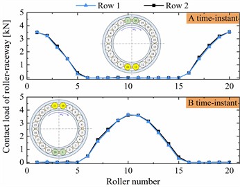
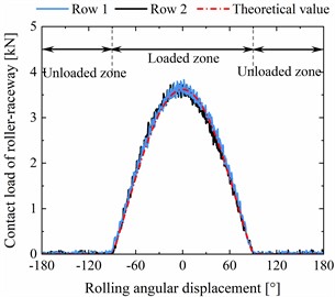
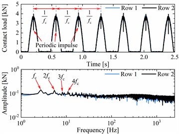
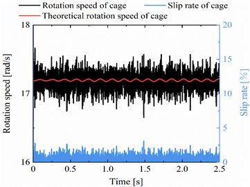
The axle-box bearings at wheelset 2 on the right side of the front bogie are selected (as seen in Fig. 1 and Fig. 4). The analysis of contact loads under normal and faulty conditions, as well as the slip characteristics under normal conditions, are depicted in Fig. 5. A localised fault, with the size of length 50.4 mm, width 2 mm and depth 2 mm, is set on the outer ring raceway of row 2 in DTRB. The vehicle running speed is set to 60 km/h, and without considering the track irregularity.
Fig. 5Theoretical verification and analysis of the correctness and rationality for the proposed model
a) Contact load history of the normal DTRB
b) Instantaneous contact load of two time-instants
c) Theoretical verification of contact load
d) Contact load history with fault and its spectrum
e) Slip analysis of the cage
f) Slip analysis of the roller
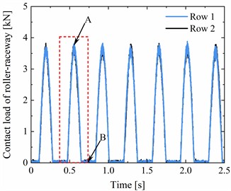
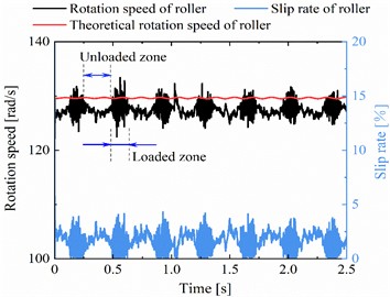
As shown in Fig. 5(a), the contact load time-history curve of the roller-outer ring raceway for the normal DTRB appears a periodic fluctuation feature with constant amplitude, and the amplitudes of the two rows are consistent. Then, we choose the contact load time-history curve of single contact cycles. On the one hand, the contact load distribution of all rollers at two time-instant from the loaded zone to the unloaded zone is analysed, as seen in Fig. 5(b). On the other hand, the contact load at single contact cycles is compared with the theoretical value, as seen in Fig. 5(c). From Fig. 5(b) and (c), we can see that the contact load curves are basically consistent with the theoretical values, and the instantaneous contact loads from A time-instant to B time-instant are reasonable in accordance with [8]. Thereafter, the contact load history and its load spectrum of faulty DTRB are discussed in Fig. 5(d). There are significant periodic impulses on the contact load history. The reciprocal of the period is just equal to the rotation frequency of cage (= 2.745 Hz), which corresponds to the fault characteristics of the outer ring. Therefore, it is feasible to use the faulty DTRB model established in this paper to study the fault characteristics of the outer ring of the axle-box bearing. Finally, the slip rate of the roller and cage are analysed to further demonstrate the rationality of the proposed model. As shown in Fig. 5(e) and (f), the actual rotation speed of the cage is consistent with its theoretical rotation speed, but the consistency between the actual rotation speed of the roller and its theoretical rotation speed is better in the loaded zone than in the unloaded zone. This is because the cage drives the roller movement in the unloaded zone, while the roller drives the cage movement in the load zone. The former is more likely to cause the roller slippage. The maximum slip rates of the cage and roller are 3.1 % and 4.3 % respectively. In summary, the coupled dynamic model proposed in this paper is reasonable and feasible.
3.2. Field test verification of the proposed model
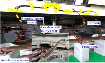
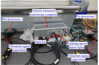
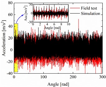
As shown in Fig. 6, the real urban rail train test is conducted to verify the correctness of the proposed model. In Fig. 6(a), the vibration response of the axle-box bearing with outer ring fault is measured through the acceleration sensor fixed in the axle-box housing. The rotational speed of the wheelset is measured through a rotating-speed sensor installed at the axle-end. In Fig. 6(b), the data acquisition system is depicted, it includes the vehicle-mounted monitoring computer and two pre-processors. Based on the rotating-speed input signal from the rotating-speed sensor in Fig. 6(a), the vehicle-mounted monitoring computer controls the pre-processor to complete the even-angle resampling of axle-box vibration signals, i.e., the order tracking. The resampled angular domain vibration signal is transmitted to the vehicle-mounted monitoring computer for storage via the data bus. As shown in Fig. 6(c), we choose the acceleration process and constant speed process between two stations to validate the proposed model. In the proposed simulation model, the size of the outer ring fault and the position of the tested axle-box are the same as those in section 3.1. The typical America 5-class track spectrum is employed. The simulation results of the proposed model are compared with on-site test data. Their vibration amplitude in angle domain and order spectrum under variable and constant speed conditions are given in Fig. 7, and the contact load characteristics from the simulation model are also shown and discussed.
Fig. 6Field tests and verification of the proposed model with outer ring raceway fault on the axle-box bearing
a) Selection of measurement positions
b) Data acquisition

c) Speed-distance curve of testing vehicle between two stations
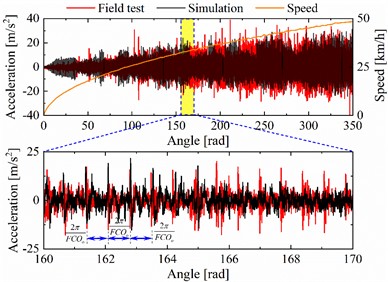
In Fig. 7(a) and (c), the resampled vibration signal in the angle domain exhibits periodic characteristics with the same intervals. And the periodic interval of the simulation and the field test is generally consistent. At the variable speed stage, the amplitude variation tendencies of the simulation and the field test are also consistent, both increasing with the increase of speed. However, owing to the difference between track irregularities in the field tests and simulations, linear representation of the rail support, and consideration of the limited number of vibration modes of the flexible body in subsection 2.2, the axle-box acceleration calculated by the proposed model is smaller than that of the test measurement in the angle domain. In Fig. 7(b) and (d), significant FCOs of the outer ring listed in Table 2 and their harmonics can be found. Under variable and constant speed conditions, the first-order FCOs of simulation and field test are 8.663, 8.662, 8.957, and 8.939 respectively. The corresponding errors with theoretical FCO are 0.36 %, 0.37 %, 3.03 % and 2.82 %. The FCO deviation of the field test is greater than that of the simulation. The reason is that the rolling elements of the axle-box bearing are slipping more severely in the field test, and the packet loss of data transmission may also cause deviation in the FCO. Furthermore, the periodic impulse can be seen in the roller-raceway contact force curve. The interval period gradually decreases as the speed increases under variable speed operating conditions. Compared to not setting up the track irregularity in Fig. 5(a) and (d), the amplitudes of the contact load will fluctuate and are not equal between two rows in actual operation simulation. It is also sufficient to demonstrate the necessity of considering vehicle-track coupling factors.
Fig. 7Verification and comparison with field test for the proposed model with the faulty DTRB
a) Comparisons of vibration signals in angle domain
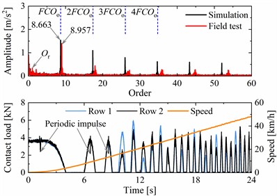
b) Comparisons of order spectrum, and contact loads
c) Comparisons of vibration signals in angle domain
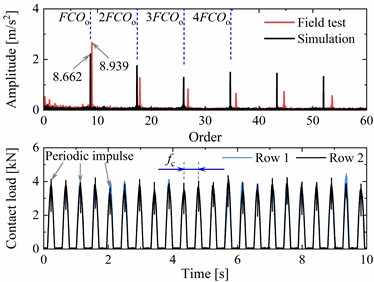
d) Comparisons of order spectrum, and contact loads
In summary, the characteristics and mechanism of the outer ring fault of the axle-box bearing are correct. By modifying various fault sizes and the vehicle operating conditions, the outer ring fault characteristics of the axle-box bearing in real scenarios can be simulated and obtained. Based on these fault features, fault diagnosis algorithms can be improved for the condition monitoring of axle-box bearings. Furthermore, the remaining life and instantaneous wear features of the faulty axle-box bearing can be evaluated though the contact loads and rolling-sliding results output by the DTRB dynamic model [14]. Therefore, the proposed coupled model can be used to analyse and reveal the fault characteristics of axle-box bearings in urban rail vehicles. It can provide a feasible theoretical basis for the research of fault diagnosis algorithms and life assessment.
4. Conclusions
In this paper, a coupled dynamics model for studying the outer ring fault characteristics and mechanisms of axle-box bearings in urban rail vehicles is established by the co-simulation method. Thereinto, the DTRB is adopted in axle-box bearing, and the outer ring raceway fault is set. The flexibilities of the wheelset, the axle-box, and the bogie frame are considered in the vehicle-track coupled dynamic model. The established coupled dynamic model is verified by the theoretical comparison and the field test respectively. The verification results are summarized as follows:
1) The distribution of contact load is consistent with the theoretical value, and the motion process of instantaneous contact load for all rollers in the DTRB is reasonable compared with the reported research. The periodic characteristics depicted by the contact load and its power spectrum of the faulty DTRB obey the fault characteristics of the outer ring raceway of the axle-box bearing. The slip rate of the roller is greater than that of the cage, but both are less than 4.3 %.
2) By the comparison on the vibration response of the axle-box in the simulation and the field test, the periodic impact characteristics caused by the outer ring raceway fault are basically consistent in angle domain. The variation tendency of the amplitude with speed is consistent under variable speed conditions. The fault order harmonics in the order spectrum of the simulation model are closer to the theoretical FCO, the maximum error is only 0.37 %. The contact load curve exhibits significant periodic impacts related to the fault characteristics of the outer ring raceway. The track irregularity can affect the load distribution of axle-box bearings.
To sum up, the coupling between the DTRB model and the vehicle-track coupling model is extremely necessary. The coupled dynamic model developed in this paper is correct and feasible. In future works, the generation mechanism of the FCO deviation between the simulation and the field test still needs to be investigated, and the faulty models of other elements of the axle-box bearing need to be developed.
References
-
D. Lin, J. D. Nelson, M. Beecroft, and J. Cui, “An overview of recent developments in China’s metro systems,” Tunnelling and Underground Space Technology, Vol. 111, p. 103783, May 2021, https://doi.org/10.1016/j.tust.2020.103783
-
J. Ding, J. Zhou, and Y. Yin, “Fault detection and diagnosis of a wheelset-bearing system using a multi-Q-factor and multi-level tunable Q-factor wavelet transform,” Measurement, Vol. 143, pp. 112–124, Sep. 2019, https://doi.org/10.1016/j.measurement.2019.05.006
-
S.-W. Hong and V.-C. Tong, “Rolling-element bearing modeling: A review,” International Journal of Precision Engineering and Manufacturing, Vol. 17, No. 12, pp. 1729–1749, Dec. 2016, https://doi.org/10.1007/s12541-016-0200-z
-
D. S. Shah and V. N. Patel, “A review of dynamic modeling and fault identifications methods for rolling element bearing,” Procedia Technology, Vol. 14, pp. 447–456, Jan. 2014, https://doi.org/10.1016/j.protcy.2014.08.057
-
R. Zhang, L. Guo, Z. Zong, H. Gao, M. Qian, and Z. Chen, “Dynamic modeling and analysis of rolling bearings with rolling element defect considering time-varying impact force,” Journal of Sound and Vibration, Vol. 562, p. 117820, Oct. 2023, https://doi.org/10.1016/j.jsv.2023.117820
-
H. Cao, L. Niu, S. Xi, and X. Chen, “Mechanical model development of rolling bearing-rotor systems: A review,” Mechanical Systems and Signal Processing, Vol. 102, pp. 37–58, Mar. 2018, https://doi.org/10.1016/j.ymssp.2017.09.023
-
Y. Wang, G. Zhang, C. Ma, K. Yang, Z. Zhang, and Z. Ren, “Explicit dynamics simulation of high-speed railway bearing based on ANSYS/LS-DYNA,” in IOP Conference Series: Materials Science and Engineering, Vol. 612, No. 3, p. 032011, Oct. 2019, https://doi.org/10.1088/1757-899x/612/3/032011
-
X. Liao, C. Yi, F. Ou, Y. Zhang, Z. Chen, and J. Lin, “Research on load characteristics of axle‐box bearing raceway under wheel‐rail excitation,” Shock and Vibration, Vol. 2021, No. 1, pp. 1–13, Nov. 2021, https://doi.org/10.1155/2021/5871667
-
J. Huo, H. Wu, D. Zhu, W. Sun, L. Wang, and J. Dong, “The rigid-flexible coupling dynamic model and response analysis of bearing-wheel-rail system under track irregularity,” Proceedings of the Institution of Mechanical Engineers, Part C: Journal of Mechanical Engineering Science, Vol. 232, No. 21, pp. 3859–3880, Dec. 2017, https://doi.org/10.1177/0954406217745336
-
X. Liao, C. Yi, Y. Zhang, Z. Chen, F. Ou, and J. Lin, “A simulation investigation on the effect of wheel-polygonal wear on dynamic vibration characteristics of the axle-box system,” Engineering Failure Analysis, Vol. 139, p. 106513, Sep. 2022, https://doi.org/10.1016/j.engfailanal.2022.106513
-
Y. Luo, F. Zhang, Z. Wang, W. Zhang, Y. Wang, and L. Liu, “Dynamic response of the axle-box bearing of a high-speed train excited by wheel flat,” Vehicle System Dynamics, Vol. 62, No. 9, pp. 2260–2282, Nov. 2023, https://doi.org/10.1080/00423114.2023.2280721
-
T. Guan, X. Deng, and J. Wang, “Dynamic response of axle box bearing for high-speed train considering wheelset flexibility and polygonal wear,” Scientific Reports, Vol. 13, No. 1, p. 22680, Dec. 2023, https://doi.org/10.1038/s41598-023-50177-2
-
X. Liao, L. He, C. Yi, W. Zhao, F. Ou, and J. Lin, “A Simulation investigation on the influence of bearing outer ring defect on dynamic vibration characteristics of the axle‐box system,” Advanced Theory and Simulations, Vol. 7, No. 1, p. 23006, Oct. 2023, https://doi.org/10.1002/adts.202300650
-
C. Yang, M. Chi, X. Wu, W. Cai, Y. Zhou, and S. Liang, “Analysis of load and life of EMU axle box bearing considering wheel polygonization evolution,” (in Chinese), Journal of Vibration Engineering, Vol. 36, No. 4, pp. 1146–1155, 2023.
-
W. Zhao, J. Ding, Q. Zhang, and W. Liu, “Investigation into the braking performance of high-speed trains in the complex braking environment of the Sichuan-Tibet Railway,” Proceedings of the Institution of Mechanical Engineers, Part F: Journal of Rail and Rapid Transit, Vol. 236, No. 7, pp. 766–782, 2022.
-
W. Tang, W. He, L. Han, and S. Xu, “Research on dynamic monitoring system of high-speed train bearing,” (in Chinese), Science Press, Beijing, China, 2022.
-
L. Yang, T. Xu, H. Xu, and Y. Wu, “Mechanical behavior of double-row tapered roller bearing under combined external loads and angular misalignment,” International Journal of Mechanical Sciences, Vol. 142-143, pp. 561–574, Jul. 2018, https://doi.org/10.1016/j.ijmecsci.2018.04.056
-
L. Guo, Y. Yu, Z. Chen, Y. Liu, and H. Gao, “Study on dynamic characteristics of urban rail transit vehicle considering faulty axle-box bearings under variable speeds,” Mechanical Systems and Signal Processing, Vol. 206, p. 110849, Jan. 2024, https://doi.org/10.1016/j.ymssp.2023.110849
-
J. Luo and T. Luo, Rolling Element Bearing Analysis, Calculate and Application. (in Chinese), Beijing, China: China Machine Press, 2009.
-
T. A. Harris and M. N. Kotzalas, Rolling Bearing Analysis – 2 Volume Set. CRC Press, 2006, https://doi.org/10.1201/9781482275148
-
F. Li, X. Li, X. Qu, H. Ma, and B. Wen, “Nonlinear characteristic analysis of shaft-bearing-pedestal system considering damage of cylindrical roller bearing,” International Journal of Non-Linear Mechanics, Vol. 150, p. 104337, Apr. 2023, https://doi.org/10.1016/j.ijnonlinmec.2022.104337
-
G. Liu, J. Zeng, R. Luo, and H. Gao, “Vibration performance of high-speed vehicles with axle box bearing defects,” Journal of Vibration and Shock, Vol. 35, No. 9, pp. 37–42, 2016, https://doi.org/10.13465/j.cnki.jvs.2016.09.007
-
W. Zhai, Vehicle-Track Coupled Dynamics. Singapore: Springer Singapore, 2020, https://doi.org/10.1007/978-981-32-9283-3
-
R. J. Guyan, “Reduction of stiffness and mass matrices,” AIAA Journal, Vol. 3, No. 2, pp. 380–380, Feb. 1965, https://doi.org/10.2514/3.2874
-
T. Li, Z. Peng, H. Xu, and Q. He, “Parameterized domain mapping for order tracking of rotating machinery,” IEEE Transactions on Industrial Electronics, Vol. 70, No. 7, pp. 7406–7416, Jul. 2023, https://doi.org/10.1109/tie.2022.3201311
-
T. Wang, M. Liang, J. Li, and W. Cheng, “Rolling element bearing fault diagnosis via fault characteristic order (FCO) analysis,” Mechanical Systems and Signal Processing, Vol. 45, No. 1, pp. 139–153, Mar. 2014, https://doi.org/10.1016/j.ymssp.2013.11.011
About this article
This work was supported by the Natural Science Foundation of Sichuan Province (grant number 2024NSFSC0019), the National Natural Science Foundation of China (Grant numbers 51875481 and 52388102) and China Postdoctoral Science Foundation (Grant number 2020M682506).
The datasets generated during and/or analyzed during the current study are available from the corresponding author on reasonable request.
Wentao Zhao: conceptualization, data curation, formal analysis, investigation, methodology, software, validation, writing-original draft preparation. Jianming Ding: conceptualization, funding acquisition, supervision, writing-review and editing. Xiaokang Liao: conceptualization, methodology, software, validation, project administration, resources, supervision. Qingsong Zhang: formal analysis, investigation, validation. Xia He: investigation, methodology, writing-review and editing. Weiwei Liu: conceptualization, funding acquisition, software, writing-review and editing.
The authors declare that they have no conflict of interest.
