Abstract
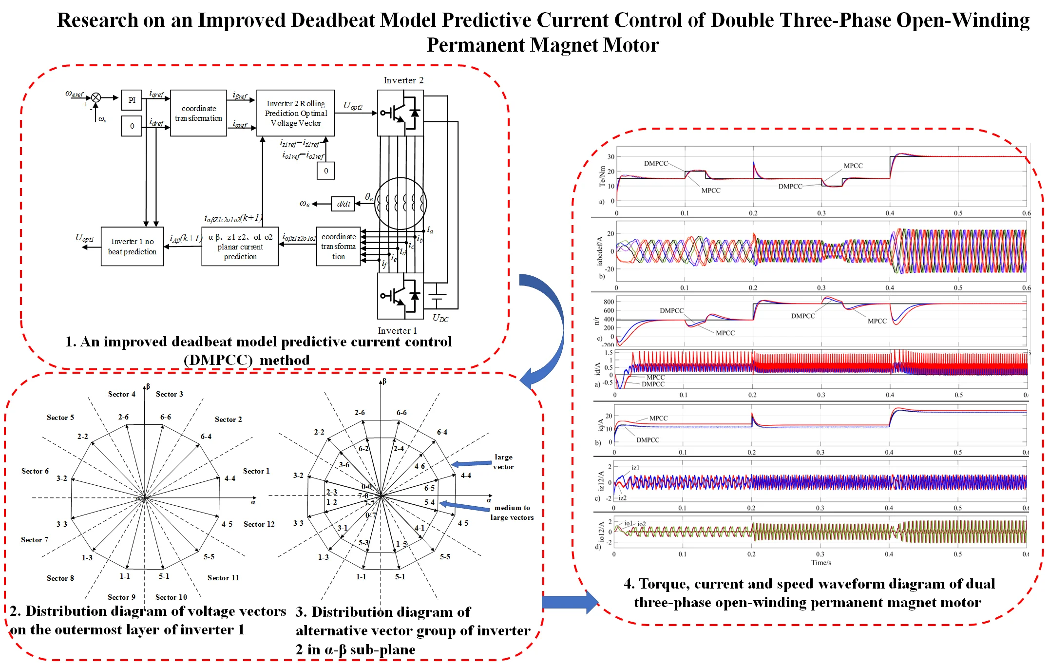
Model predictive current control has high control accuracy and good control performance, and has been widely applied in the control strategy of dual three-phase permanent magnet synchronous motors. This article proposes an improved deadbeat model predictive current control (DMPCC) method by analyzing the mathematical model of a dual three-phase open-winding permanent magnet synchronous motor. One inverter predicts and calculates the optimal voltage vector through the deadbeat model, while the other inverter calculates the optimal voltage vector through the value function rolling optimization. This method reduces the computational workload of the controller, avoids the delay problem of the traditional model predictive current control (MPCC) method, improves the system's response speed, effectively suppresses the current in the harmonic sub-plane, and reduces torque ripple. The simulation results have verified the accuracy and speed of the above control method.
Highlights
- Combines deadbeat model prediction with value function rolling optimization prediction.
- Reducing the complexity of the prediction algorithm.
- The DMPCC method is more sensitive to current control.
- The motor has better dynamic performance and anti-interference capabilities.
- Effectively suppressing the low-order harmonics of the stator current.
- Reducing electromagnetic torque ripple, and improving the efficiency of the motor system.
1. Introduction
In recent years, new energy technologies mainly based on electricity have developed rapidly, and motor drives, as the main body of electricity consumption, have received widespread attention[1-3]. The open-winding multiphase motor drive system has the advantages of high output power, high torque density, strong fault tolerance, and low single-phase rated power [4-6], which can ensure the increase of system capacity while supplying power to the low-voltage DC bus. However, due to the increase in the number of inverter phases, the control algorithm becomes more complex. The harmonic impedance of multiphase motors is small, there are multiple harmonic sub-planes, and the more phases there are, the more difficult it is to suppress harmonic currents, which increases stator losses and torque ripple. The phase angle of an asymmetric dual three-phase motor is 30°, and its spatial magnetic potential distribution is consistent with that of a symmetric twelve phase motor. It can effectively eliminate 5th and 7th harmonic magnetic potential and 6th torque ripple, resulting in smoother torque output and lower torque ripple. Therefore, this paper focuses on the research of an open-winding asymmetric dual three-phase motor.
At present, research on open-winding multiphase motor drive technology mainly focuses on model predictive current control, direct torque control, fault-tolerant control, and other aspects [7]. Reference [8] proposed an efficient direct torque control strategy based on space vector modulation for dual three-phase permanent magnet synchronous motor. This strategy adopts the space vector modulation technique to compensate for the stator flux error, and then the continuous smooth response of the vector control and the rapid response of direct torque control are both achieved. However, this method fails to effectively reduce the harmonic current in the - sub-plane, and the torque ripple suppression effect is limited. Reference [9] combines model predictive torque control with the principle of deadbeat control, selecting the target voltage vector from adjacent vectors of the expected voltage vector, avoiding the complex operation of rolling optimization of the value function, and improving the system response speed. However, this control method has limited effectiveness in suppressing fifth and seventh current harmonics, and fails to effectively reduce harmonic content, resulting in ripple in the output torque. To reduce torque ripple, reference [10] proposes a dual virtual vector model predictive current control strategy. The zero vector and adjacent virtual vectors are combined to construct the expected voltage vector. Reference [11] proposes a three-vector predictive current control method for permanent magnet synchronous motors based on an improved sliding mode perturbation observer without a finite set model. However, these methods involve a large amount of computation, which reduces the dynamic response speed of the motor. Reference [12] proposes a model predictive current control strategy based on a six-phase stationary coordinate system. The control algorithm is simple and improves the response speed of the motor, but the electromagnetic torque ripple of the motor cannot be completely eliminated. Reference [13,14] both propose an improved model predictive current control strategy that can reduce the harmonic content of the stator winding and reduce torque ripple. However, the motor has a large dependence on system parameters, and there are current prediction errors in systems with varying parameters. Therefore, reference [15] proposes a finite set predictive current control based on sampling error. The open-wound motor parameters are not used in the prediction algorithm, but the method cannot effectively reduce the harmonic components in the stator winding, and the output torque contains ripples. Reference [16] proposes an adaptive model predictive current control strategy for an isolated bus open-winding five phase permanent magnet motor. By optimizing the selection of the output voltage vector of the dual five phase inverter, switch device losses and stator current harmonics can be reduced. However, this control strategy cannot be used in a common bus topology. Reference [17] proposes a model predictive current control strategy for open-winding nine phase permanent magnet motors. By synthesizing virtual voltage vectors online in the harmonic subspace, the stator current harmonic content is reduced, and the torque ripple of the motor is reduced. However, this method requires online synthesis of virtual voltage vectors, which requires a large amount of computation and complex control.
This article proposes an improved deadbeat model predictive current control method for dual three-phase open-winding permanent magnet synchronous motors, which divides the inverter into two single six-phase inverters for driving control. Among them, a six-phase inverter calculates the optimal voltage vector by using the fundamental wave plane deadbeat model to predict the current control method, thereby avoiding the huge computational workload caused by rolling optimization of the value function. Another six-phase inverter calculates the optimal voltage vector through the prediction current control method based on the fundamental and harmonic plane models, effectively suppressing the third, fifth, and seventh harmonics. A dual three-phase open-winding permanent magnet motor drive system based on a combination of deadbeat model prediction and value function rolling optimization prediction reduces the number of value function evaluations, reduces the complexity of prediction algorithms, suppresses low order harmonics of stator current, reduces electromagnetic torque ripple, and improves motor system efficiency.
2. Drive topology and mathematical model of dual three-phase open-winding permanent magnet synchronous motor
2.1. A Drive topology of dual three-phase open-winding permanent magnet synchronous motor
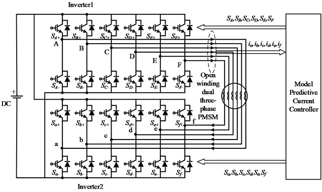
The dual three-phase permanent magnet synchronous motor with an open-winding structure opens the neutral point of the traditional dual three-phase motor and uses dual inverters for power supply, improving the flexibility of the control system [18, 19]. According to whether the dual inverters are powered by a common DC bus, they can be divided into isolated topology and common bus topology. The DC side of the common bus open-winding structure is powered by a single DC power source, with a simple topology and high utilization of DC voltage. However, due to the existence of common mode voltage and zero sequence current circuits, special modulation methods are needed to suppress zero sequence current [20]. This article studies the model predictive current control strategy for a common bus line open-winding dual three-phase permanent magnet synchronous motor. It effectively suppresses the third, fifth, and seventh harmonics of the driving system while using a single DC power supply. The topology structure is shown in Fig. 1.
Fig. 1Topology diagram of dual three-phase open-winding permanent magnet synchronous motor drive system
2.2. Mathematical model of dual three-phase open-winding permanent magnet synchronous motor
The dual three-phase open-winding permanent magnet synchronous motor is driven by two six-phase inverters, each of which contains six bridge arms and two power switching devices on each bridge arm. Using the vector to represent the output state of each six-phase inverter bridge arm, the state vector of six-phase inverter 1, where , , , , , respectively represent the switch state of the bridge arm of six-phase inverter 1. If the upper bridge arm is conductive and the lower bridge arm is cut off, it is 1; otherwise, it is 0. Similarly, the state vector of six-phase inverter 2, where , , , , , respectively represent the bridge arm switch states of six-phase inverter 2. From this, it can be seen that each six-phase inverter has a total of 26 = 64 switch states [21, 22].
When analyzing the mathematical model of a dual three-phase open-winding permanent magnet synchronous motor, the vector decoupling method is usually used. The Clarke coordinate transformation is applied to the stator current equation in a six-phase natural coordinate system to obtain the continuous domain stator current equation of the dual three-phase open-winding permanent magnet motor for - sub-plane, - sub-plane, and - sub-plane. The sub-plane is orthogonal to each other. The stationary transformation matrix of the dual three-phase motor is shown in Eq. (1):
The first two lines of Eq. (1) map the fundamental and (1, 2, 3…) harmonics of the motor to the - sub-plane, due to the rotation plane of the air gap magnetic flux of the motor and - sub-plane are consistent, therefore the current component on the - sub-plane participates in the process of electromechanical energy conversion. The middle two rows of Eq.(1) map the (1, 3, 5…) harmonic of the motor to the - sub-plane, and the last two rows of Eq. (1) map the (1, 3, 5…) harmonic of the motor to the - sub-plane. Due to the orthogonality of the - and - sub-planes with the air gap magnetic flux rotation plane of the motor, the current components on the - and - sub-planes do not participate in the electromechanical energy conversion process, and there are harmonic current components, also known as harmonic sub-planes. When controlling the dual three-phase open-winding permanent magnet synchronous motor drive system, the given current values of the axis, axis, axis, and axis in the - and - sub-planes should be uniformly set to 0 to minimize the impact of harmonic sub-plane currents on the motor control process.
The use of model predictive current control methods requires discretization of the continuous domain stator current. The forward Euler discretization formula can be used to obtain the stator current equations in the -, -, and - sub-planes of the dual three-phase open-winding permanent magnet synchronous motor in the discrete domain, as shown in Eq. (2):
wherein: , , , , , are the discrete domain components of the stator currents in the -, -, and - sub-planes, , , , , , are the predicted values of , , , , , , , , , , , are the components of the synthesized voltage vectors of the two six-phase inverters in the -, -, and - sub-planes, is the control period, is the stator resistance, is the stator direct axis inductance, is the stator quadrature axis inductance, is the stator zero-sequence inductance, is the amplitude of the fundamental flux linkage of the permanent magnet, is the amplitude of the third harmonic flux linkage of the permanent magnet, is the feedback angular velocity of the motor, and is the feedback position angle of the motor.
3. Space voltage vector of six-phase inverter
The dual three-phase open-winding permanent magnet synchronous motor drive system has 64 switching states per six-phase inverter. Taking the six-phase inverter 1 as an example, according to Eqs. (3-4), each switching state has a corresponding voltage vector on the - sub-plane and the - sub-plane:
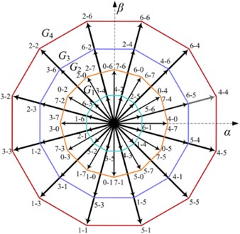
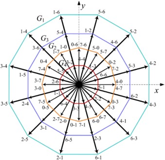
where, is the DC side voltage, and and are the spatial voltage vectors mapped to the - sub-plane and - sub-plane, respectively, for each switching state. From Eqs. (4-5), a voltage vector diagram of the 64 switching states of the six-phase inverter on the - sub-plane and - sub-plane can be drawn, as shown in Fig. 2.
Fig. 2The voltage vector diagram of a) α-β sub-plane and b) z1-z2 sub-plane
a)
b)
Each voltage vector in Fig. 2 is represented by a pair of octal numbers. Converting the octal numbers into binary numbers can obtain the switch state corresponding to this vector, such as "2-3" representing the switch state (010011), which means that the upper arms of b, e, and f are on, and the rest of the arms are off. Each plane contains 48 valid vectors, corresponding to 60 switch states, as well as 4 zero vectors, corresponding to switch states "0-0, 0-7, 7-0, 7-7". According to the grouping of voltage vectors, the 48 valid voltage vectors can be divided into 4 regular dodecagons, consisting of 12 large vectors, 12 medium-large vectors, 12 medium vectors, and 12 small vectors.
In the - subplane depicted in Fig. 2(a), when one set of inverter switches is fully open or fully closed (switch state is 0 or 7), the stator voltage vector is entirely output by the other set of inverter in a non-zero vector state, which can be equivalent to a conventional three-phase motor. This scenario corresponds to 24 switching states. According to Eq. (3), 12 medium vectors can be obtained, with an amplitude of , forming the ring in Fig. 2(a). Similarly, according to Eq. (3), when the output vectors of the two sets of inverters differ by 30°, 12 large vectors can be synthesized, with an amplitude of 0.644, forming the ring in Fig. 2(a); when the output vectors of the two sets of inverters differ by 90°, 12 medium-large vectors can be synthesized, with an amplitude of 0.417, forming the ring in Fig. 2(a); when the output vectors of the two sets of inverters differ by 150°, 12 small vectors can be synthesized, with an amplitude of 0.173, forming the ring in Fig. 2(a).
Similarly, in the - sub-plane depicted in Fig. 2(b), when one set of inverter switches is fully open or fully closed (switch state is 0 or 7), 12 medium vectors with an amplitude of can be obtained according to Eq. (4), forming the G2 ring in Fig. 2(b). When the output vectors of the two sets of inverters differ by 30°, 90°, or 150°, 12 large vectors, 12 medium-large vectors, and 12 small vectors can be synthesized, respectively, forming the , , and rings in Fig. 2(b). It can be observed that the large vectors in Fig.2(a) become small vectors in Fig. 2(b), and the small vectors in Fig. 2(a) become large vectors in Fig. 2(b).
In this control system, inverter 1 uses 12 large vectors as the optimal target voltage vector, and inverter 2 uses 12 large vectors, 12 medium-large vectors, and 4 zero vectors to participate in evaluating the minimum value of the value function, obtaining the optimal target voltage vector for inverter 2.
4. Simplified model prediction current control of dual three-phase open wound permanent magnet synchronous motor
4.1. Control block diagram
The simplified model predictive current control block diagram of a dual three-phase open-wound permanent magnet synchronous motor is shown in Fig. 3.
Fig. 3Control block diagram of simplified model prediction circuit
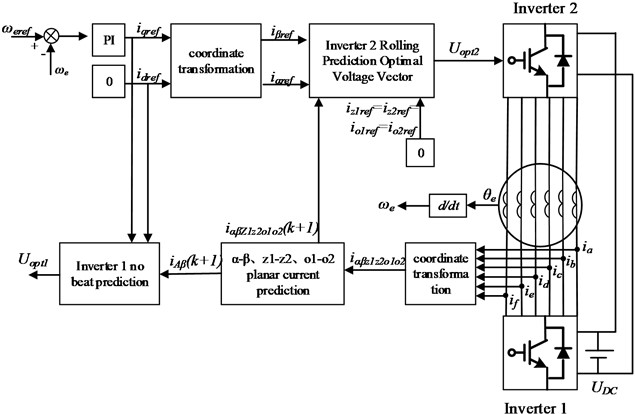
The sensor detects the feedback angular velocity of the rotor of the dual three-phase motor, and further obtains the given angular velocity and the error of the feedback angular velocity. The proportional integral controller PI adjusts to obtain the given current on the -axis. The given current on the -axis is set to 0, and and are transformed through inverse rotation coordinates to obtain the given current on the -axis and the given current on the -axis in the - sub-plane.
Using the deadbeat current prediction control method, the given voltage on the -axis and the given voltage on the -axis in the - sub-plane of the dual three-phase open-winding permanent magnet motor are calculated, and the sector position of the synthesized voltage vector is determined to determine the optimal large voltage vector of inverter 1.
Calculate the errors of the optimal large voltage vector of inverter 1 and the 28 reference voltage vectors of inverter 2 in the - sub-plane, - sub-plane, and - sub-plane, evaluate the minimum value of the value function, and obtain the optimal target voltage vector of inverter 2, thereby completing the model predictive current control of the dual three-phase open-winding permanent magnet synchronous motor.
4.2. Control method of inverter 1
The inverter 1 calculates the given voltage and the given voltage of the - sub-plane of the dual three-phase open-winding permanent magnet motor based on the deadbeat current prediction control principle and the - axis given currents and . The essence of deadbeat current prediction control is to eliminate the error between the state variable of the system at the next moment and the reference quantity, so that the output current follows the given value of the current without any error, thereby selecting the optimal control quantity as the reference quantity for the next moment. According to the forward Euler discretization formula in Eq. (2), the prediction model of the three sub-plane currents at time can be obtained. Due to the short sampling time, the current and voltage reference values of the - sub-plane can be approximately equivalent to the expected values of the current and voltage at time , as shown in Eq. (5):
where, , , , and are the reference values of the stator current and stator voltage on the -axis and -axis at time . Finally, by substituting Eq. (5) into Eq. (2), the given voltage equation of the dual three-phase motor in the - sub-plane can be calculated, as shown in Eq. (6):
Based on the -axis reference voltage and the -axis reference voltage , the sector position angle of the synthesized given voltage vector can be obtained, as shown in Eq. (7):
To simplify the calculation of model predictive current control, the 12 largest voltage vectors on the outermost layer of inverter 1 are taken as candidate target voltage vectors. The - sub-plane is divided into 12 sectors, with each candidate target voltage vector in a sector. The distribution diagram of the outermost layer voltage vectors of inverter 1 is shown in Fig. 4.
According to the sector position angle of the synthesized given voltage vector and Fig. 4, the sector in which the synthesized given voltage vector is located can be determined, and the optimal target voltage vector of inverter 1 can be determined. Because the open-winding drive system has two inverters, the optimal target voltage vector of the dual three-phase motor needs to be jointly determined by inverter 1 and inverter 2. In order to facilitate the joint evaluation of the minimum value of the value function with the optimal target voltage vector of inverter 2, it is necessary to decompose the optimal target voltage vector of inverter 1 in the - sub-plane, sub-plane, and - sub-plane to obtain the -axis optimal target voltage component , β-axis optimal target voltage component , -axis optimal target voltage component , -axis optimal target voltage component , -axis optimal target voltage component , and -axis optimal target voltage component of inverter 1. The correspondence between the sector position angle of inverter 1 and the optimal voltage vector is shown in Table 1, where is the common DC bus voltage of inverter 1 and inverter 2.
Fig. 4Distribution diagram of voltage vectors on the outermost layer of inverter 1
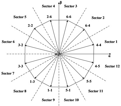
Table 1Corresponding relationship between sector position angle and optimal voltage vector of inverter 1
Sector position angle and sector number | axis component | axis component | axis component | axis component | axis component | axis component | |
0-/6 | Sector 1 | 0.6220 | 0.1667 | 0.04466 | 0.1667 | –0.1667 | –0.1667 |
/6-/3 | Sector 2 | 0.4553 | 0.4553 | –0.1220 | –0.1220 | 0.1667 | –0.1667 |
/3-/2 | Sector 3 | 0.1667 | 0.6220 | 0.1667 | 0.04466 | 0.1667 | 0.1667 |
/2-2/3 | Sector 4 | –0.1667 | 0.6220 | –0.1667 | 0.04466 | –0.1667 | 0.1667 |
2/3-5/6 | Sector 5 | –0.4553 | 0.4553 | 0.1220 | –0.1220 | –0.1667 | –0.1667 |
5/6- | Sector 6 | –0.6220 | 0.1667 | –0.0447 | 0.1667 | 0.1667 | –0.1667 |
–-5/6 | Sector 7 | –0.6220 | –0.1667 | –0.0447 | –0.1667 | 0.1667 | 0.1667 |
–5/6-2/3 | Sector 8 | –0.4553 | –0.4553 | 0.1220 | 0.1220 | –0.1667 | 0.1667 |
–2/3-/2 | Sector 9 | –0.1667 | –0.6220 | –0.1667 | –0.0447 | –0.1667 | –0.1667 |
–/2-/3 | Sector 10 | 0.1667 | –0.6220 | 0.1667 | –0.0447 | 0.1667 | –0.1667 |
–/3-/6 | Sector 11 | 0.4553 | –0.4553 | –0.1220 | 0.1220 | 0.1667 | 0.1667 |
–/6-0 | Sector 12 | 0.6220 | –0.1667 | 0.04466 | –0.1667 | –0.1667 | 0.1667 |
After determining the optimal target voltage vector of inverter 1, the switching signals of the 12 power switching devices of inverter 1 can be obtained based on the sector position of the voltage vector. The correspondence between sector position and switching signal is shown in Table 2.
Table 2Correspondence between sector position and switch signal
Sector code | ||||||
Sector 1 | 1 | 0 | 0 | 1 | 0 | 0 |
Sector 2 | 1 | 1 | 0 | 1 | 0 | 0 |
Sector 3 | 1 | 1 | 0 | 1 | 1 | 0 |
Sector 4 | 0 | 1 | 0 | 1 | 1 | 0 |
Sector 5 | 0 | 1 | 0 | 0 | 1 | 0 |
Sector 6 | 0 | 1 | 1 | 0 | 1 | 0 |
Sector 7 | 0 | 1 | 1 | 0 | 1 | 1 |
Sector 8 | 0 | 0 | 1 | 0 | 1 | 1 |
Sector 9 | 0 | 0 | 1 | 0 | 0 | 1 |
Sector 10 | 1 | 0 | 1 | 0 | 0 | 1 |
Sector 11 | 1 | 0 | 1 | 1 | 0 | 1 |
Sector 12 | 1 | 0 | 0 | 1 | 0 | 1 |
4.3. Control method of inverter 2
Select 12 large vectors on the outermost layer, 12 medium-large vectors on the second outermost layer, and 4 zero vectors of the inverter 2 to form a set of candidate target voltage vectors, with a total of 28 vectors. The distribution of the 28 candidate target voltage vectors on the - sub-plane, - sub-plane, and - sub-plane is shown in Figs. 5-7.
Fig. 5Distribution diagram of alternative vector group of inverter 2 in α-β sub-plane
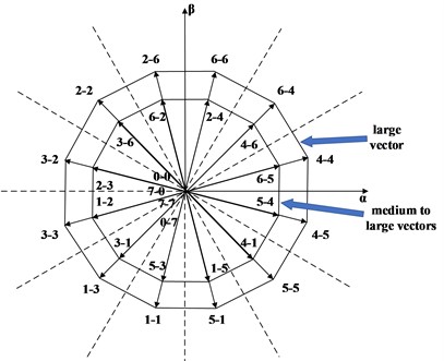
Fig. 6Distribution diagram of alternative vector group of inverter 2 in z1-z2 sub-plane
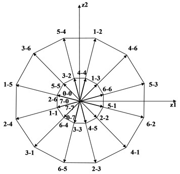
Fig. 7Distribution diagram of alternative vector group of inverter 2 in o1-o2 sub-plane
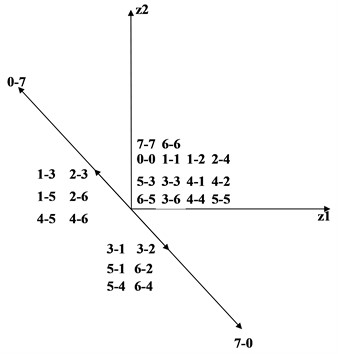
According to the distribution rule of target voltage vectors on the three sub-planes, the - sub-plane, the - sub-plane, and the - sub-plane can obtain 28 candidate target voltage vectors with -axis component , -axis component , -axis component , -axis component , -axis component , -axis component on the - sub-plane, the - sub-plane, and the sub-plane, respectively. .
Subtracting the -axis optimal target voltage component , -axis optimal target voltage component , -axis optimal target voltage component , -axis optimal target voltage component , -axis optimal target voltage component , and -axis optimal target voltage component of inverter 1 from the 28 candidate target voltage vectors of inverter 2 in the corresponding axes, we can obtain 28 synthesized candidate voltage vectors on the - sub-plane, - sub-plane, and - sub-plane of the dual three-phase open-winding permanent magnet synchronous motor. Their component sizes on the -axis, -axis, -axis, -axis, -axis, and -axis are respectively , , , , , and .
Substituting the synthesized candidate voltage components into Eq. (8), the magnitude of the corresponding value function of the candidate voltage vector can be evaluated in turn, and the minimum value is taken. The corresponding voltage vector is the synthesized target voltage vector , which determines the optimal target voltage vector component of inverter 2:
5. Experimental results
In order to verify the effectiveness and correctness of the above control method, we used MATLAB software to model and simulate a dual three-phase open-winding permanent magnet motor. The motor parameters used are as follows: stator resistance 0.67 Ω, stator direct axis inductance 2.46 mH, stator quadrature axis inductance 2.46 mH , stator zero-sequence inductance 0.5 mH, fundamental permanent magnet flux linkage 0.0885 Wb, third harmonic permanent magnet flux linkage 0.005 Wb, and motor pole pair number 5.
Fig. 8 shows the torque, stator current, and speed waveforms of a dual three-phase open-winding permanent magnet motor. Fig. 8(a) shows the waveform diagram of electromagnetic torque and load torque; Fig. 8(b) shows the waveform diagram of stator winding current; Fig. 8(c) shows the waveform diagram of rotor speed. In the torque and speed waveforms, the black line represents the reference value, the blue line represents the waveform curve controlled by the DMPCC method, and the red line represents the waveform curve controlled by the MPCC method. At 0.2 s, we adjusted the given speed from 375 n/min to 750 n/min. From the simulation diagram, it can be seen that the phase current frequency of the motor increases. Compared with MPCC, the motor speed increases faster under DMPCC control, and finally stabilizes at 750 n/min. At 0.4 s, the load torque suddenly changed from 15 Nm to 30 Nm, and the phase current amplitude of the motor increased. Compared with MPCC, the electromagnetic torque of the motor under DMPCC control increased more rapidly, with smaller torque ripple and speed fluctuation. Finally, the electromagnetic torque stabilized at 30 Nm and the speed stabilized at 750 n/min. It can be seen that after adopting an improved deadbeat model prediction current control strategy, the operation amount of the system is greatly reduced, avoiding complex value function rolling optimization processes. Under this method control, the speed, torque, and stator current of the motor have good steady-state and dynamic performance.
Fig. 8Torque, stator current and speed waveform diagram of dual three-phase open-winding permanent magnet motor
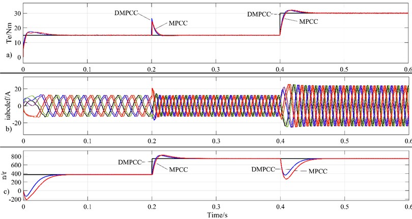
Fig. 9 shows the current waveform diagrams of the - axis, - sub-plane, and - sub-plane of the motor. Fig. 9(a) shows the waveform diagram of the -axis current; Fig. 9(b) shows the waveform diagram of the -axis current; Fig. 9(c) shows the waveform diagrams of the -axis and -axis currents; Fig. 9(d) shows the waveform diagrams of the -axis and -axis currents. The blue line in the Fig. 9 is the waveform curve controlled by the DMPCC method, and the red line is the waveform curve controlled by the MPCC method. As can be seen from the Fig. 9, there is still a certain deviation between the -axis current and the value of 0 using the DMPCC method, which needs further debugging to eliminate. However, due to the significant reduction in the number of rolling optimization iterations of the value function by the DMPCC method, it is more sensitive to - axis current control. Compared to the traditional MPCC method, when using the DMPCC method, the -axis current pulsation is smaller and the q-axis current is closer to the given value.When the given values of speed and torque change, although the current frequency of the -axis and two harmonic sub-planes increases significantly, they can be stabilized around 0, indicating that this method can effectively suppress harmonic currents in the motor and reduce torque ripple. At 0.4 s, the load torque suddenly increases, and the -axis current rapidly increases, ensuring that the output torque increases in time, demonstrating that this control method has good dynamic performance.
Fig. 9Current waveform diagram of d-q axis, z1-z2 sub-plane and o1-o2 sub-plane of motor
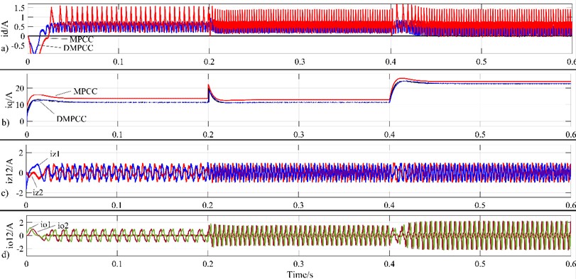
Fig. 10Waveform diagrams of motor torque, stator current, and speed under load disturbance
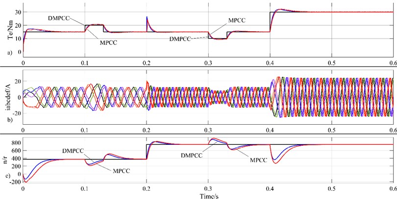
Fig. 10 depicts the waveform diagrams of the output torque, stator current, and speed of the motor under load disturbance. Fig. 10(a) shows the waveform diagram of electromagnetic torque and load torque; Fig. 10(b) shows the waveform diagram of stator winding current; Fig. 10(c) shows the waveform diagram of rotor speed. In the torque and speed waveform diagrams, the black line represents the load torque waveform and speed reference value, respectively. The blue line represents the torque and speed waveforms controlled by the DMPCC method, while the red line represents the torque and speed waveforms controlled by the MPCC method. At 0.1 s, a positive disturbance of 5 Nm was added to the load torque, lasting for 0.03 s; at 0.3 s, a negative disturbance of –5 Nm was added to the load torque, lasting for 0.03 s. From the waveform diagrams, it can be observed that when the load torque suddenly increases or decreases, the magnitude of the stator current will rapidly increase or decrease. Compared to the MPCC method, when a load disturbance occurs, the output torque response of the DMPCC method is more rapid. Whether it is a positive disturbance or a negative disturbance, the output torque of DMPCC can quickly change according to the change in load torque, and the speed fluctuation is also smaller. This indicates that after simplifying the value function for rolling optimization, the sensitivity of motor control is improved, and the motor exhibits high stability and anti-interference capability.
6. Conclusions
This paper proposes a simplified model predictive current control strategy for dual three-phase open-winding permanent magnet synchronous motors, in which inverter 1 obtains optimal voltage vectors through a fundamental sub-plane deadbeat model predictive current control method, and inverter 2 obtains optimal voltage vectors through a value function rolling optimization model predictive current control method. Through experiments, this article has reached the following conclusions:
1) This method combines deadbeat model prediction with value function rolling optimization prediction, and is applied to dual three-phase open-winding permanent magnet synchronous motor drive systems, reducing the number of value function evaluations and reducing the complexity of the prediction algorithm.
2) Compared to traditional MPCC methods, when using the DMPCC method, the -axis current ripple is smaller, the -axis current is closer to the given value, and the DMPCC method is more sensitive to - axis current control.
3) Under the control of DMPCC, when the load torque suddenly increases, the electromagnetic torque increases more rapidly and the speed fluctuation is smaller; When the given speed increases, the motor speed rises faster, indicating that the motor under DMPCC control has better dynamic performance and anti-interference capabilities.
4) DMPCC achieves coordinated control of the fundamental and harmonic sub-planes of the inverter 2, effectively suppressing the low-order harmonics of the stator current, reducing electromagnetic torque ripple, and improving the efficiency of the motor system.
References
-
H. Tang, O. Sha, Z. Yang, and D. Xu, “Deadbeat two-vector model predictive current control for open-winding primary permanent-magnet linear motor,” Journal of Vibroengineering, Vol. 24, No. 3, pp. 577–590, May 2022, https://doi.org/10.21595/jve.2022.22248
-
J. Cui, J. Ji, W. Zhao, T. Tao, L. Huang, and H. Tang, “Decoupled fault-tolerant model predictive current control for dual three-phase PMSMs with harmonic compensation,” IEEE Transactions on Power Electronics, Vol. 38, No. 2, pp. 2285–2294, Feb. 2023, https://doi.org/10.1109/tpel.2022.3210039
-
C. Wang, J. Ji, H. Tang, T. Tao, and W. Zhao, “Improved model predictive current control for linear vernier permanent-magnet motor with efficient voltage vectors selection,” IEEE Transactions on Industrial Electronics, Vol. 70, No. 3, pp. 2833–2842, Mar. 2023, https://doi.org/10.1109/tie.2022.3169827
-
Y. Luo and C. Liu, “Elimination of harmonic currents using a reference voltage vector based-model predictive control for a six-phase PMSM motor,” IEEE Transactions on Power Electronics, Vol. 34, No. 7, pp. 6960–6972, Jul. 2019, https://doi.org/10.1109/tpel.2018.2874893
-
I. Zoric, M. Jones, and E. Levi, “Arbitrary power sharing among three-phase winding sets of multiphase machines,” IEEE Transactions on Industrial Electronics, Vol. 65, No. 2, pp. 1128–1139, Feb. 2018, https://doi.org/10.1109/tie.2017.2733468
-
Z. Song, Z. Dong, W. Wang, S. Liu, and C. Liu, “A novel modulation strategy for asymmetrical six-phase series-winding PMSM based on predictive controller,” IEEE Transactions on Industrial Electronics, Vol. 70, No. 6, pp. 5592–5603, Jun. 2023, https://doi.org/10.1109/tie.2022.3199861
-
Q. Huang, L. Luo, X. Zhang, and L. Diao, “Fault tolerant control for open winding brushless DC motor with power device failure,” Journal of Electrical Engineering and Technology, Vol. 19, No. 5, pp. 3175–3189, Jan. 2024, https://doi.org/10.1007/s42835-024-01784-0
-
W. Zhang, P. Zhang, X. H. Zhang, and X. F. Shen, “An effective direct torque control based on space vector modulation for DTP-PMSM,” Applied Mechanics and Materials, Vol. 416-417, pp. 480–485, Sep. 2013, https://doi.org/10.4028/www.scientific.net/amm.416-417.480
-
W. Xie et al., “Finite-control-set model predictive torque control with a deadbeat solution for PMSM drives,” IEEE Transactions on Industrial Electronics, Vol. 62, No. 9, pp. 5402–5410, Sep. 2015, https://doi.org/10.1109/tie.2015.2410767
-
L. Yao and W. Liu, “Model predictive current control of dual three-phase permanent magnet synchronous motor based on double virtual vectors,” in Journal of Physics: Conference Series, Vol. 2803, No. 1, p. 012028, Jul. 2024, https://doi.org/10.1088/1742-6596/2803/1/012028
-
N. Huang, Y. Zhang, and B. Tian, “Model-free three-vector predictive current control of permanent magnet synchronous motor based on improved sliding mode observer,” in Journal of Physics: Conference Series, Vol. 2785, No. 1, p. 012097, Jun. 2024, https://doi.org/10.1088/1742-6596/2785/1/012097
-
T. Zhao, J. Zhu, M. Li, K. Zang, and H. Liao, “Model predictive current control of fault-tolerant permanent magnet rim drive motor based on six-phase stationary coordinate system,” Journal of Electrical Engineering and Technology, Vol. 19, No. 4, pp. 2337–2346, Dec. 2023, https://doi.org/10.1007/s42835-023-01715-5
-
Z. Liu, Y. Yang, P. Li, B. Li, and G. Wang, “Improved double-vector model predictive control to reduce current THD for ANPC-5L inverters,” Electrical Engineering, Vol. 106, No. 3, pp. 2285–2295, Oct. 2023, https://doi.org/10.1007/s00202-023-02068-y
-
J. Yue, J. Zhu, T. Zhao, Z. Wang, and W. He, “Three-vector model predictive current control strategy of PMSM for marine electric propulsion based on three-level inverter,” Journal of Electrical Engineering and Technology, Vol. 19, No. 4, pp. 2311–2321, Dec. 2023, https://doi.org/10.1007/s42835-023-01702-w
-
M. S. Mousavi, S. A. Davari, F. Flores‐Bahamonde, C. Garcia, and J. Rodriguez, “Sampling error‐based model‐free predictive current control of open‐end winding induction motor with simplified vector selection,” IET Electric Power Applications, Vol. 17, No. 3, pp. 358–369, Dec. 2022, https://doi.org/10.1049/elp2.12273
-
Y. Du, J. Ji, W. Zhao, T. Tao, and D. Xu, “Self-adapted model predictive current control for five-phase open-end winding PMSM with reduced switching loss,” IEEE Transactions on Power Electronics, Vol. 37, No. 9, pp. 11007–11018, Sep. 2022, https://doi.org/10.1109/tpel.2022.3167249
-
H. Wang, X. Wu, X. Zheng, and X. Yuan, “Model predictive current control of nine-phase open-end winding PMSMs with an online virtual vector synthesis strategy,” IEEE Transactions on Industrial Electronics, Vol. 70, No. 3, pp. 2199–2208, Mar. 2023, https://doi.org/10.1109/tie.2022.3174241
-
Y. Cheng, D. Sun, W. Chen, and H. Nian, “Model predictive current control for an open-winding PMSM system with a common DC bus in 3-D space,” IEEE Transactions on Power Electronics, Vol. 35, No. 9, pp. 9597–9607, Sep. 2020, https://doi.org/10.1109/tpel.2020.2972996
-
C. Jiang, H. Liu, P. Wheeler, F. Wu, and J. Huo, “An optimized modulation for five-phase open-end winding PMSM with sliding clamped strategy,” IEEE Transactions on Industrial Electronics, Vol. 70, No. 9, pp. 8819–8829, Sep. 2023, https://doi.org/10.1109/tie.2022.3212385
-
P. C. Mavila and P. P. Rajeevan, “A five-level torque controller based DTC scheme for open-end winding five-phase IM drives with single DC source and auxiliary plane harmonic elimination,” IEEE Transactions on Industry Applications, Vol. 58, No. 2, pp. 2063–2074, Mar. 2022, https://doi.org/10.1109/tia.2022.3140361
-
J. J. Aciego, I. Gonzalez Prieto, and M. J. Duran, “Model predictive control of six-phase induction motor drives using two virtual voltage vectors,” IEEE Journal of Emerging and Selected Topics in Power Electronics, Vol. 7, No. 1, pp. 321–330, Mar. 2019, https://doi.org/10.1109/jestpe.2018.2883359
-
M. Ayala, J. Doval-Gandoy, O. Gonzalez, J. Rodas, R. Gregor, and M. Rivera, “Experimental stability study of modulated model predictive current controllers applied to six-phase induction motor drives,” IEEE Transactions on Power Electronics, Vol. 36, No. 11, pp. 13275–13284, Nov. 2021, https://doi.org/10.1109/tpel.2021.3081347
About this article
The authors have not disclosed any funding.
The datasets generated during and/or analyzed during the current study are available from the corresponding author on reasonable request.
Ou Sha proposed an improved deadbeat model predictive current control strategy, and completed the formula derivation and paper writing. Hongyu Tang completed the construction of the simulation experimental model, the collection and organization of experimental data and simulation waveforms, and assisted Sha Ou in revising the paper.
The authors declare that they have no conflict of interest.
