Abstract
Since the helicopters are required to fulfil many different attitudes during actual flight and are exposed to low amplitude and high number of cycles of vibration loads for a long period of time, the stresses on its rotor structure will be more complicated, which will lead to the rotor blades being subjected to larger stresses and causing fatigue damage. This paper proposes a combination of fluid-solid coupling and nCode fatigue simulation of helicopter rotor blade structure to study the stress distribution, danger point and fatigue life of rotor blades in hovering and forward flight state, so as to provide a reference basis for the judgement of helicopter rotor blade fatigue damage and the enhancement of safety performance. The results show that the maximum stress of the helicopter in the forward flight state is larger than that in the hovering state, and the maximum stress of the rotor blade in the forward flight state of the helicopter is located at the root of the blade as 166.89 MPa; and the fatigue life in the two states is obtained by the joint simulation method of Workbench-nCode, and the fatigue life in the forward flight state is reduced by 0.726 % compared with that in the hovering state. Therefore, the combined method of fluid-solid coupling and nCode fatigue simulation proposed in this paper can provide an effective research method for the design and optimisation process of helicopter rotor blades.
1. Introduction
Helicopters, with their outstanding characteristics of flexibility and speed, can do low altitude, low speed and nose direction unchanged manoeuvre flight, especially rapid vertical take-off and landing [1]. The propeller assembly, consisting of two blades and a hub, was attached to the engine crankshaft [1]. Helicopter rotor blade structure is the power core component, which is done by rotating the air around the blade to move, and constantly push the air backward, with the help of the reaction force of the air on the blade, so as to make the production of tension or thrust [2]. The rotor blade structure is always in a complex, cyclic alternating aerodynamic environment, so the fatigue problem involved in the rotor system is a high-frequency, low-stress amplitude high-cycle fatigue problem [3]. Aiming at this problem, this paper selects a certain type of rotor blade structure and obtains the blade stress load data within a single rotational cycle through the rotor blade structure fluid-solid coupling simulation method; and proposes the blade fatigue life analysis method to realize the fatigue life estimation of the blade structure, and provides the reliability study for the blade structure.
2. Mathematical model
2.1. Fluid mechanics control equations
Fluid coupling follows the basic assumptions and relevant laws of fluid mechanics, and the fluid domain follows the fluid mass conservation equation and conservation of momentum equation:
where is the static pressure; is the gas density; is the velocity vector; is the turbulent viscosity; is the Reynolds stress.
2.2. Fluid-solid coupling equation
Combined with the conservation theorem, the fluid-solid coupling in the fluid and solid contact surface, the solid and fluid stress, deformation and other mechanical properties are consistent with the corresponding conservation relations:
where: is the stress of the fluid; is the stress of the solid; is the unit direction vector of the fluid; is the unit direction vector of the solid; is the displacement of the fluid; is the displacement of the solid.
3. Finite element modeling
In this paper, a certain type of helicopter blade structure, the design of the wing is mainly used NACA0012 wing, blade wingspan diameter of 2185.2 mm, hub diameter of 120 mm, the maximum chord length of 91.4 mm, the specific parameters are shown in Table 1.
Table 1Rotor blade parameters
Section number | Distance between centers / mm | Chord length / mm | Mounting angle / ° | Relative thickness |
1 | 75.3 | 91.4 | 17.18 | 39 % |
2 | 710.1 | 62.9 | 14.7 | 24 % |
3 | 873.9 | 55.2 | 10.26 | 17 % |
4 | 1092.6 | 45.7 | 8.8 | 13 % |
Airfoil design using Profili airfoil design software, then the 3D coordinate data were imported into Solidworks and processed to obtain the 3D model of the blade as shown in Fig. 1.
Fig. 13D model of blade structure

a) Top view

b) Front view
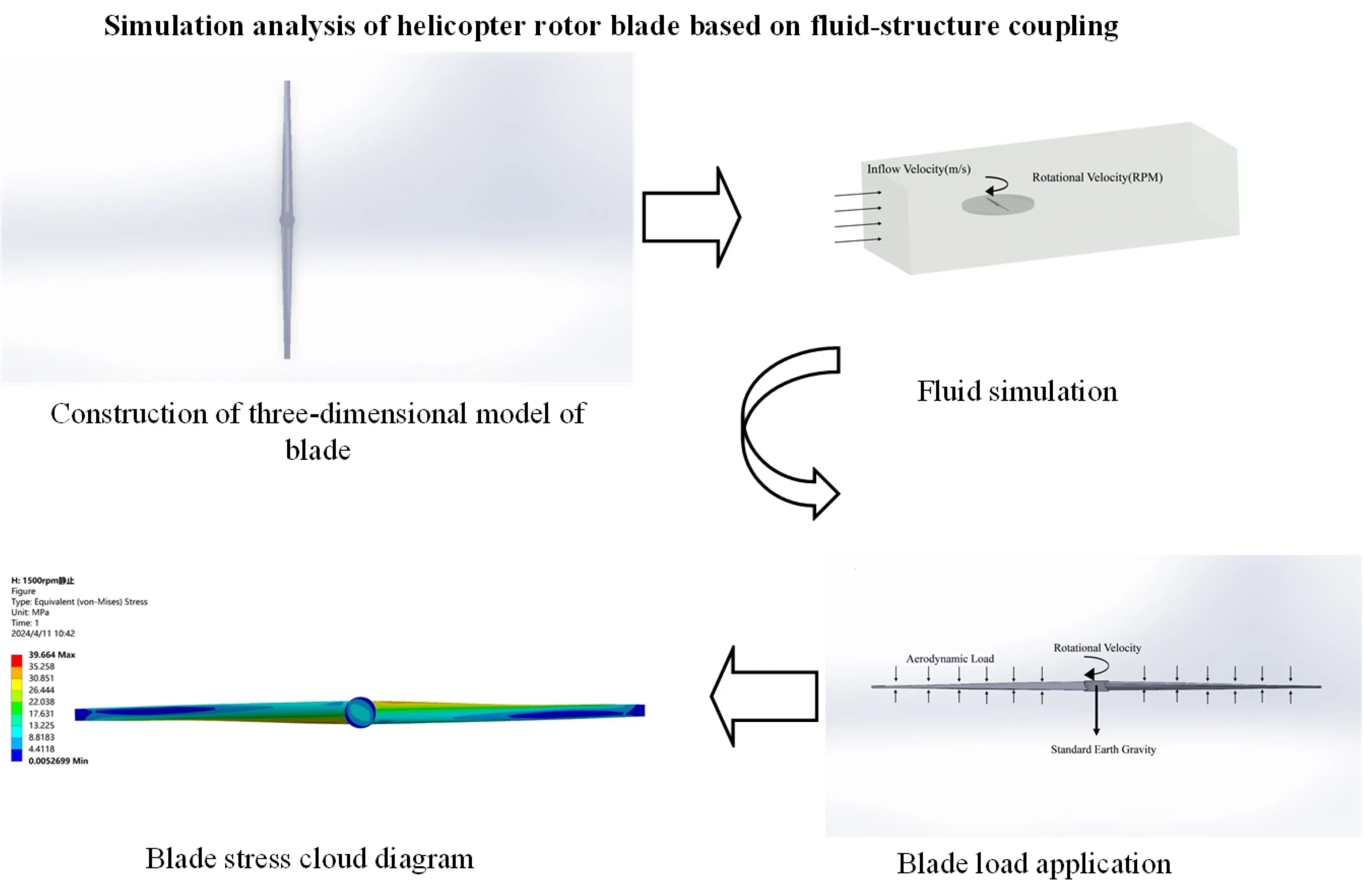
4. Rotor blade structure fluid-structure coupling simulation
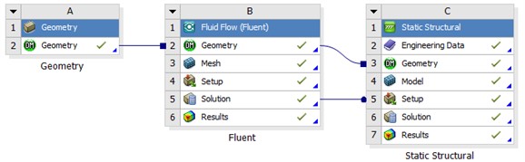
In this paper, the flow-solid coupling simulation of the blade is carried out with the help of Ansys Workbench software, and its process is shown in Fig. 2.
As can be seen from Fig. 2, the flow of Workbench fluid-solid coupling analysis is as follows: the finite element model is processed by Geometry first, and then imported into Fluent module for hydrodynamic analysis, and then the results of the hydrodynamic analysis are inputted into Static Structural module for solid mechanical analysis.
Fig. 2Workbench flow-solid coupling process
4.1. Fluid mechanics analysis
In order to carry out fluid analysis of the rotor blade and realize the rotation of the rotor in the fluid, it is necessary to establish a fluid domain around the rotor blade, and at the same time, the flow field is divided into regions, the flow field consists of static and rotating domains, the static domain is used to simulate the fluid around the blade, and the rotating domain is used to simulate the rotation of the rotor blade. In this paper, the fluid region is divided by Mesh module, the mesh size of the stationary domain is 120 mm, the mesh size of the rotating domain is 20 mm, and the mesh size of the fluid-solid coupling interface is 3 mm, and the refinement of the mesh size of the fluid-solid coupling interface can ensure the accuracy of the aerodynamic load solution. The fluid domain mesh is shown in Fig. 3.
Fig. 3Fluid domain mesh
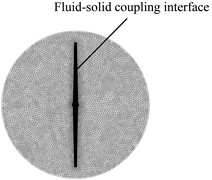
a) Rotate field mesh
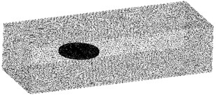
b) Stationary domain mesh
After the grid division is completed, set the inlet and outlet of the wind and the fluid-solid coupling interface, and set the necessary parameters of the flow field, the specific steps are: (1) setting the fluid as air and selecting the epsilon Realizable turbulence module can make the calculation of the rotating flow of the rotor structure more in line with the real situation [5]; (2) by setting the boundary conditions and the rotating domain velocity, the inlet of the stationary domain is set as the velocity inlet, the outlet is set as the pressure outlet, and the outer surface is set as the non-slip wall [6]; (3) choosing the SIMPLE algorithm for the solution; (4) selecting a certain type of helicopter route flight procedure to get the rotor in the whole flight mission typical state loads [7]. The specific flight stages and rotational speeds are shown in Table 2.
The above parameter settings can be used to obtain the pressure distribution on the upper and lower airfoil surfaces of the rotors in the hovering and forward flight states of the helicopter.
Table 2Structural steel material parameters
Flight stage | Ground take-off | Climb | Cruises | Approach | Ground idle |
Rotational velocity (RPM) | 2400 | 2100 | 1800 | 1200 | 750 |
Flight speed (m·s-1) | 5.14 | 38.58 | 46.30 | 33.44 | 5.14 |
4.2. Solid mechanics analysis
In this paper, the flow-solid coupling rotor blade structure material is a single structural steel material, and the material parameters are shown in Table 3 [8].
Table 3Structural steel material parameters
Density (kg/m3) | Bulk modulus (Pa) | Shear modulus (Pa) | Poisson | Tensile ultimate strength (Pa) | Tensile yield strength (Pa) |
7850 | 1.6667E+11 | 7.6923E+10 | 0.3 | 4.6E+08 | 2.5E+08 |
4.2.1. Rotor blade mesh division
After setting the material parameters, the mesh delineation of the blade structure is carried out with a mesh size of 10 mm, and the mesh delineation results are shown in Fig. 4.
The average mesh quality is 0.80056, which meets the calculation requirements.
Fig. 4Rotor blade structure grid

4.2.2. Constraints setting
In order to realize the rotary motion of the rotor, constraints need to be imposed on the two blades [9]. In the actual flight of the helicopter, the blade structure and the hub are connected by connectors, and the blade hub remains stationary; therefore, the fixed constraints are set on the rotor blade hub, which is consistent with the actual situation [10].
4.2.3. Load addition
The aerodynamic load import in Fluent is applied to the rotor blade surface, and at the same time the rotor is given a rotational speed (consistent with the rotational speed of the rotating domain) to provide centrifugal force load and gravitational acceleration. The application of aerodynamic load and inertial load in Workbench is shown in Fig. 5.
Fig. 5Application of blade loads
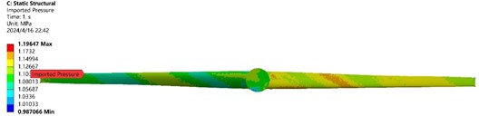
a) Aerodynamic load
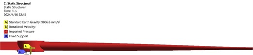
b) Inertial load
When the overall solid mechanics analysis of the blade structure is set up, then the solid strength analysis is solved in the solver, and the calculation results are viewed in the post-processing after the solution is completed.
The results of the flow field solution of the helicopter in hovering and forward flight are applied to the surface of the solid rotor structure, and then the above constraints and load conditions are added to carry out the solid mechanics analysis of the rotor blade, and finally the calculation results are viewed in the post-processing. When the maximum rotational speed of the rotors is selected in the ground take-off attitude, the equivalent stress and total deformation cloud of the rotors during hovering and forward flight of the helicopter is shown in Fig. 6.
The material of rotor blade structure is structural steel, and its yield strength is 250 MPa. The maximum rotational speed of the blade in the above process is 2400 RPM, and the maximum stress value of the blade structure in the rotational process is calculated to be 166.89 MPa, and the maximum stress point is located at the root of the blade, and the stress value is much smaller than the yield strength of the material, which meets the strength requirements.
Fig. 6Equivalent stress for different states during cruise

a) Equivalent stress in hovering state
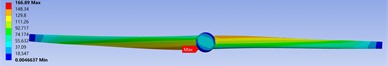
b) Equivalent stress in forward flight state
Fig. 7Helicopter blade structure fatigue life simulation results
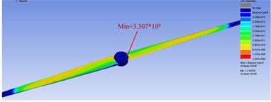
a) Fatigue simulation results of blade structure under hovering condition
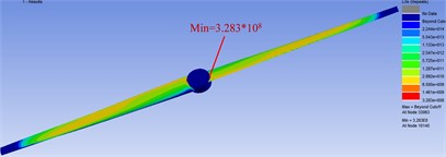
b) Fatigue simulation results of blade structure under hovering condition
NCode software is commonly used in engineering fatigue life analysis software. In this paper, the fatigue life analysis simulation results of the blade structure using Workbench-nCode joint simulation are shown in Fig. 7. Under the joint simulation, the location of the blade fatigue hazard point is 10140 nodes, and the hazard point fatigue life of the blade root is 3.283×10⁸ and 3.307×10⁸ cycles for forward flight and hovering respectively.
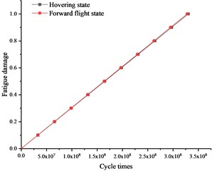
As can be seen from the above comparison curve diagram, the maximum equivalent stresses of the helicopter’s blades in the forward flight state are greater than the maximum equivalent stresses in the hovering state under the states of ground take-off, climb, cruise, approach, and ground jogging, etc. The maximum equivalent stresses of the rotor blades in the forward flight and hovering states are 166.89 MPa and 166.3 MPa respectively, and the maximum stresses in the rotor structure are less than the permissible stresses in the materials. The fatigue damage to the blade structure increases linearly with the cycle times. When the helicopter blade rotates at cruise speed, the fatigue life of the fatigue hazardous point of the root of the blade in forward flight and hovering is 3.283×10⁸ and 3.307×10⁸ cycles, and the cycle times in the forward flight state is reduced by 0.726 % compared to that of the hover state, which is within the reasonable error range and verifies the reliability of the method in this paper.
Fig. 8Comparison of the rotor maximum equivalent stress in hovering and forward flight at different rotational speeds
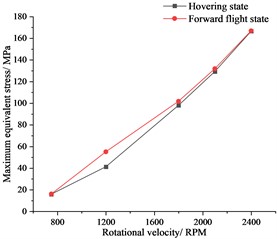
Fig. 9Comparison of rotor cycle times in hover and forward flight
5. Conclusions
In this paper establishes a three-dimensional simulation model of the rotor blade structure, proposes a combination of fluid-solid coupling and nCode fatigue simulation of the helicopter blade structure, and analyses the stress distribution and fatigue life of the rotor blade structure in the hovering state and the forward flight state under each attitude of the helicopter, as well as the fatigue life of the dangerous points. The results show that:
1) The maximum stresses of the rotor blade structure in the hovering and forward flight states of the helicopter in all flight attitudes are much smaller than the permissible stresses of the materials, which meets the strength requirements.
2) The equivalent stress at the root of the blade is the largest during the forward flight of the helicopter, but it will not affect the normal flight of the helicopter, and the rotor structure is in a relatively safe state, but it needs to be strengthened in the actual design or the design of anti-pull-off structure at the root of the blade blade, so as to improve the durability and safety performance of the blade.
3) Based on the method proposed by nCode software, the fatigue life of the blade root fatigue hazard point in forward flight is 3.283×10⁸ cycles, and the number of fatigue life cycles in the forward flight state is reduced by 0.726 % compared with that in the hovering state, which verifies the reasonableness and reliability of the proposed method.
References
-
Y. Liu, “Analysis of dynamic characteristics of helicopter main blade fatigue test system,” (in Chinese), Harbin Institute of Technology, 2016.
-
H.-C. Lee, Y.-H. Hwang, and T.-G. Kim, “Failure of aircraft propeller assembly,” Engineering Failure Analysis, Vol. 11, No. 3, pp. 305–312, Jun. 2004, https://doi.org/10.1016/j.engfailanal.2003.08.002
-
P. Ma, “Optimized design and analysis of aerodynamic performance of rotor blade for high altitude long endurance UAV,” (in Chinese), Nanchang University of Aeronautics and Astronautics, 2022.
-
Z. Yu, “Fatigue progressive damage analysis of helicopter composite rotor blades,” (in Chinese), Nanjing University of Aeronautics and Astronautics, 2012.
-
J. Qin and L. Zhang, “Aerodynamic analysis of UAV rotor blade based on fluid-structure coupling,” (in Chinese), Technology Innovation and Application, Vol. 13, No. 14, pp. 40–44, 2023.
-
X. Yan, X. Chen, and H. Li, “Numerical simulation of stepped spillway flow based on standard and Realizable k~ε turbulence models,” (in Chinese), Water Conservancy Science and Technology and Economy, Vol. 21, No. 10, pp. 29–31, 2015.
-
F. Cao, “Composite propeller-fluid-solid coupling,” (in Chinese), Shanghai Jiao Tong University, 2013.
-
W. Wei, “Research on simulation and analysis method of aviation propeller vibration characteristics,” (in Chinese), Machinery Design and Manufacture, No. 5, pp. 194–198, 2021.
-
B. Wang, “Numerical simulation and optimisation of aerodynamic characteristics of advanced rotor blade based on CFD method,” (in Chinese), Nanjing University of Aeronautics and Astronautics, 2012.
-
L. Zhao, “Strength analysis of helicopter rotor blade based on fluid-solid coupling,” (in Chinese), Harbin Engineering University, 2014.
-
M. Tang, “Research on modelling and simulation analysis of small single-rotor helicopter rotor blades,” (in Chinese), Wuhan Engineering University, 2022.
About this article

The authors have not disclosed any funding.
The datasets generated during and/or analyzed during the current study are available from the corresponding author on reasonable request.
The authors declare that they have no conflict of interest.
