Abstract
In this paper, the mechanical properties of C/C composite bolts at normal temperature are studied. The strength performance of bolts under different load conditions of tension and shear is tested, which shows that they have different failure modes. It is concluded that the strength performance and failure mode of C/C bolts are directly related to the structural size and the braiding characteristic of the bolt. This can provide a basis for the optimal design of C/C bolts.
1. Introduction
Carbon fiber reinforced carbon matrix composite (C/C) has been widely used in high-speed aircraft and other type high-temperature bearing structures [1]. As the preparation level of C/C materials continues to develop and improve, its structural design characteristics [2], performance test and characterization [3-4], and its strong dependence on the actual use environment have also been the research direction for many years.
Complex Composite structures need to solve the problem of reliable connection between components, and the evaluation of connection performance should be given. Bolting, riveting, welding and bonding can be widely used to connect C/C components with each other and with metals [5], but only mechanical connection by bolts can meet the requirements of repeated disassembly, which is the most basic connection method in practical engineering structures. In the process of designing and verifying the thermal structure of high-speed aircraft, advanced countries pay attention to the connection performance between components and emphasize the need to ensure the connection reliability in harsh flight environment [6].
It can be used for mechanical connection between C/C thermal structural components, including high-temperature alloy bolts, ceramic bolts and C/C composite bolts. However, the potential characteristics and thermal expansion characteristics between high-temperature alloy bolts and C/C materials are significantly different, while ceramic bolts are prone to brittle fracture, so C/C bolt connection with the same material has many advantages. A lot of achievements about bolted joints have been made by different scholars from numerical calculation [7-8], experiment [9] and bolt tightening torque characteristics [10]. However, most of these studies focus on the comprehensive performance of bolted joints, the research on the performance test of C/C bolt itself [11] and the correlation between C/C bolt and the internal structure of the material is relatively few. The performance of C/C bolts under different design variables is discussed in reference [12] (such as diameter) and the verification methods is provided, but only the tensile load condition is considered, and the influencing factors of micro-braided configuration of C/C material are not involved. With the more extensive use of C/C materials, continuing to study and master the performance and influencing factors of C/C connections such as C/C bolts can not only improve the thermal structure design level of high-speed aircraft, but also have strong academic innovation.
In this paper, the performance of C/C bolts at room temperature under different loading conditions of tension, shear, and tension-shear combination is tested, and their different failure modes are observed and the characteristics are summarized. The relationship between size configuration, material microstructure, and strength performance of C/C bolts is analyzed. It is shown that all the above factors obviously affect the strength failure mode and performance of C/C bolts, so attention should be paid to the differences between C/C bolts and ordinary metal bolts in practical application.
2. The strength characteristics of C/C bolts under tensile load
The C/C bolts for the test are designed by this paper according to the research requirements of the supporting project, and the C/C material is prepared and the bolt is machined by the Chinese Institute of Aerospace Materials and Technology. First, the C/C material with a density of about 2.0 g/cm3 was prepared using prepreg impregnation and pyrolysis (PIP) technology. Then the bolt test piece is obtained by machining the C/C material. Two kinds of bolt specimens with M10 standard thread and T10 coarse thread were processed. The experiment was carried out on the Instron electronic universal testing machine of Northwestern Polytechnical University, P.R. China, and the load and displacement data were recorded by sensors. The loading rate of the testing machine was 0.3 mm/min, which was consistent with the tensile test of materials.
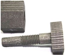
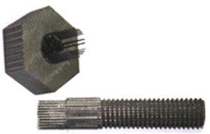
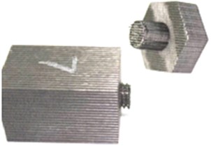
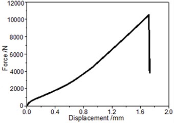
In this paper, it is mainly concerned with the performance of C/C bolts with carbon fiber bundles as reinforcements. Strength values are obtained through tensile tests. As can be seen from Fig. 1, the failure of C/C bolts can be divided into three different forms: when the meshing length between the bolt and the nut is small, the thread pulls off. When the meshing length increases to a certain extent (which is related to the thread type, about 2 times the bolt diameter), the thread pull-off failure will no longer occur, but the root of the thread segment of the bolt mainly be fractured. However, if the thickness of the bolt head is thin (about the same as the bolt diameter), the pull-out failure between the screw and the bolt head may also occur. During the thread pull-off failure, more carbon matrix chips were produced and the pull-out characteristics of fiber bundles were not obvious. The results show that the fiber at the thread position has no major effect on the load. Both the other two kinds of failure have obvious fiber bundle pull-out phenomenon, which shows that the bolt body is mainly supported by longitudinal fiber bundles under tensile load.
Fig. 1Three different tensile failure modes of C/C bolts: a) thread pull-off, b) pull-out between screw and bolt head, c) thread fracture at root, d) force-displacement curve corresponding to mode c)
a)
b)
c)
d)
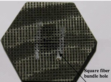
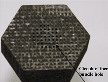
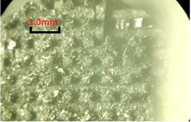
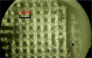
The surface of the test piece after the fiber bundle is pulled out is observed and compared as shown in Fig. 2. It is found that the carbon fiber bundles woven in orthogonal three-dimensional directions present square cross-section holes, indicating that the fiber bundles in three directions are closely arranged in orthogonal space. However, the carbon fiber bundles of other weaving methods generally show circular cross-section holes after being pulled out, which indicates that the density of fiber bundles and the degree of extrusion between them are lower. Therefore, there are more dense carbon fiber bundles in the bolt with orthogonal three-dimensional directions weaving. With the same properties such as carbon matrix strength and interfacial bonding strength, more carbon fiber bundle content leads to the improvement of tensile strength of C/C bolts. It is shown that the average tensile strength of M10 standard thread orthogonal three-dimensional directions woven C/C bolt is close to 140 MPa, which is more than 18 % higher than that of other braided C/C bolts.
Fig. 2The morphological comparison after the fiber bundle is pulled out between the bolt with a) orthogonal three-dimensional directions weaving and b) other braided bolt
c)
b)
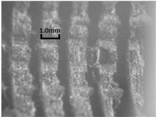
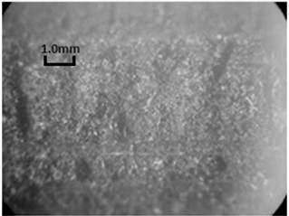
The thread pull-off failure mode in Fig. 1(a) is determined by the thread strength and it is related to the specific thread design mode. The comparative observation of thread pull-off fracture between M-thread and T-thread is given in Fig. 3. It can be seen that the fracture surface of T-shaped thread is smooth after failure, and the fiber bundle is completely cut off, indicating that the failure position is basically at the root of the thread. While the root of M-type thread remains intact, and it is damaged in the relatively upper position of the thread. Shear failure mode is dominant for both M-type and T-type threads, indicating that the thread pull-off strength mainly depends on the strength of carbon matrix strength of C/C materials.
Fig. 3The comparison of micro-morphology of thread pull-off: a) M-type thread, b) T-type thread
a)
b)
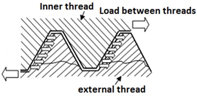
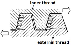
The differences between M-type thread and T-type thread are analyzed, we can see that the root of M-type thread is wider. When bearing tensile load, the nut and bolt are staggered. Mechanical analysis in this case can be equivalent to squeezing the thread surface and shearing the thread root. The root of M-type thread is wider, so it has stronger ability to bear shear failure. Experimental results show that when the thread engagement length of M10 bolt is 15 mm, thread pull-off failure will no longer occur, indicating that the nut thickness requirement has been met. But T10 bolt will still have thread pull-off failure under the same engagement length.
Fig. 4Mechanical characteristics and failure trace diagram of a) M-type thread and b) T-type thread
a)
b)
3. Strength characteristics of C/C bolts under shear or tension-shear combined load
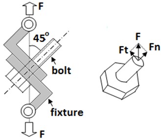
Tensile-shear coupling load is applied by loading in the direction oblique to the bolt axis. The mechanical condition of bolt specimen is shown in Fig. 5. The failure section of orthogonal three-dimensional directions woven C/C bolt under shear or tension-shear combined load is shown in Fig. 6.
Fig. 5The combined tension-shear loading method of bolt and its mechanical condition
Under the shear load, the fiber bundles perpendicular to the shear plane are cut neatly, and the fracture section is smooth and neat. Under the tension-shear combined load, the fracture section of C/C bolt is similar to shear failure, but there are some fiber bundle pull-out areas. These indicate that the stress components produced by tensile load and shear load act on different positions of C/C bolt cross section.
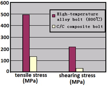
From Fig. 6, it is shown that the bolt has no fiber reinforcement effect of crack deflection when it is subjected to shear or tension-shear combined load. It is considered that this is because the carbon fiber bundles of orthogonal three-dimensional directions braided C/C bolts cross each other in 90° space, and the fiber bundles perpendicular to the load produce shear failure, while the fiber bundles in the other two directions do not play a reinforcing role. So the overall shear strength of this type of bolt is relatively low. In Fig. 7, the test results of C/C bolt in this paper are compared with the mechanical properties of high-temperature alloy bolt in the literature [11], and the difference in shear strength (about 7.5 times) is more significant than tensile strength (about 3.8 times).
Fig. 6a) Shear failure section and b) tensile-shear combined failure section of C/C bolt
a)
b)
So it is not the most reasonable way to bear the shear load for C/C bolts that carbon fiber bundles are orthogonal to each other at 90° direction. In order to improve the overall bearing capacity of C/C bolts, it is necessary to appropriately increase the content of carbon fiber bundles in other directions.
Fig. 7Strength comparison between C/C bolt and high-temperature alloy bolt
4. Conclusions
The complex factors affecting the mechanical properties of C/C bolted connections should be paid attention to in the thermal structure design of composite materials. In order to improve the performance of joints, it is necessary to optimize the size configuration and fabric form of C/C bolts. In this paper, test data of C/C bolts are obtained, and the following performance rules are derived through analysis:
1) Under tensile load, C/C bolts have many different failure modes, such as thread pull-off, thread fracture at root of bolts, pull-out between screw and bolt head, etc. Different failure modes are related to the size and configuration of bolts. The performance of M-type thread is better than that of T-type thread.
2) For C/C bolts with carbon fiber bundles orthogonal three-dimensional directions weaving, the performance is low under shear load and tension-shear combined load. It is mainly because the fiber bundle only produces shear failure and has no obvious performance enhancement effect. So the optimum design should appropriately increase the fiber content in the direction of ±45°.
3) It is necessary to further accumulate test data and establish the design specification of C/C bolts.
References
-
J. Wang, L. Xu, and W. Li, “Research progress on C/C composites for aerospace applications,” Aerospace Materials and Technology, Vol. 52, pp. 1–12, 2022, https://doi.org/10.12044/j.issn.1007-2330.2022.02.001
-
M. J. Shan and L. B. Zhao, “Research progress in reinforcement design and analysis of composite bolted joints,” (in Chinese), Acta Materiae Compositae Sinica, Vol. 40, No. 7, pp. 3771–3784, 2023, https://doi.org/10.13801/j.cnki.fhclxb.20221123.002
-
X. Li, Z. Tan, L. Wang, J. Zhang, Z. Xiao, and H. Luo, “Experimental investigations of bolted, adhesively bonded and hybrid bolted/bonded single-lap joints in composite laminates,” Materials Today Communications, Vol. 24, p. 101244, Sep. 2020, https://doi.org/10.1016/j.mtcomm.2020.101244
-
M. Shishesaz and M. Hosseini, “A review on stress distribution, strength and failure of bolted composite joints,” Journal of Computational Applied Mechanics, Vol. 49, No. 2, pp. 415–429, 2018.
-
Y. Tang, Y. Ren, W. Zhao, Z. Zhou, and L. Han, “Mechanical properties of all-C/C composite hybrid bonded/bolted joints,” Journal of Reinforced Plastics and Composites, Vol. 42, No. 7-8, pp. 377–390, Sep. 2022, https://doi.org/10.1177/07316844221127486
-
D. Glass, “Physical challenges and limitations confronting the use of UHTCs on hypersonic vehicles,” in 17th AIAA International Space Planes and Hypersonic Systems and Technologies Conference, Apr. 2011, https://doi.org/10.2514/6.2011-2304
-
P. J. Gray and C. T. Mccarthy, “A global bolted joint model for finite element analysis of load distributions in multi-bolt composite joints,” Composites Part B: Engineering, Vol. 41, No. 4, pp. 317–325, Jun. 2010, https://doi.org/10.1016/j.compositesb.2010.03.001
-
C. Stocchi, P. Robinson, and S. T. Pinho, “A detailed finite element investigation of composite bolted joints with countersunk fasteners,” Composites Part A: Applied Science and Manufacturing, Vol. 52, pp. 143–150, Sep. 2013, https://doi.org/10.1016/j.compositesa.2012.09.013
-
Y. F. Zhang, Z. G. Zhou, S. D. Pan, and Z. Y. Tan, “Comparison on failure behavior of three-dimensional woven carbon/carbon composites joints subjected to out-of-plane loading at room and high temperature,” Composites Communications, Vol. 23, p. 10056, 2021.
-
X. H. Liu et al., “Tightening torque characteristics of C/C composite threaded fasteners at room temperature,” (in Chinese), Acta Materiae Compositae Sinica, Vol. 36, No. 4, pp. 921–926, 2019, https://doi.org/10.13801/j.cnki.fhclxb.20180608.002
-
P. G. Sun et al., “Failure modes analysis of C/C composites bolt in tensile strength,” (in Chinese), Aerospace Materials and Technology, Vol. 47, No. 6, pp. 36–38, 2017, https://doi.org/10.12044/j.issn.1007-2330.2017.06.006
-
Y. Y. Chang et al., “Design method of anti-oxidation C/C composite screw,” (in Chinese), Journal of Harbin Engineering University, Vol. 43, No. 7, pp. 1006–1012, 2022.
About this article

The present work was supported by the Undergraduate Innovation and Entrepreneurship Training Program in Heilongjiang Province (No. 202310217201), National Natural Science Foundation of China (No. U20B2002).
The datasets generated during and/or analyzed during the current study are available from the corresponding author on reasonable request.
The authors declare that they have no conflict of interest.
