Abstract
The CFG pile technology is primarily employed for foundation reinforcement, offering cost-saving benefits and demonstrating significant reinforcement effects. Consequently, it has gained widespread utilization. However, due to its unique composition and exceptional strength characteristics, investigating the dynamic properties of rubber particle loess-CFG poses significant challenges. In this study, a numerical simulation approach is employed to investigate the dynamic characteristics of rubber particle loess-CFG and its deformation response under dynamic loading is analyzed. The results indicate that the deformation of rubber particle loess-CFG remains minimal under static loading, while it significantly increases under dynamic loading. However, the vertical and horizontal displacements at the top of the mattress layer are comparatively smaller than those observed in loess-CFG, highlighting their seismic stability. The mattress layer of the rubber particle loess-CFG undergoes vertical compression and deformation, while being horizontally squeezed towards the central region. The horizontal displacement and its variation range are significantly greater than that of the entire pile and the soil between piles. Therefore, it is crucial to analyze the material properties, thickness, and extent of the mattress layer during design in order to mitigate its influence. When subjected to dynamic loading at the base of the model, the rubber particle loess-CFG exhibits a strip distribution of vertical displacement which gradually decreases from bottom to top. Moreover, as focal depth increases, the impact of dynamic loading on foundation deformation diminishes. Consequently, rubber particle loess-CFG provides a dual functionality of enhancing foundation strength while effectively resisting dynamic deformations. These research findings provide a theoretical basis for designing reinforced foundations using rubber particle loess-CFG and offer an innovative approach for recycling waste tire rubber particles.
Highlights
- This research adopted a foundation treatment method that combines rubber particles and cement fly ash gravel piles to improve the characteristics of loess.
- This research results enrich the knowledge system of foundation treatment.
- The foundation treatment method is expected to promote the development of the resource utilization of waste tires.
1. Introduction
Loess exhibits high porosity, extensive vertical joint, and is predominantly collapsible, resulting in poor engineering properties under heavy loads and dynamic conditions. Extensive research has been conducted to enhance the properties of loess to meet engineering requirements [1]-[4], among which the dynamic characteristics of improved loess have become a research hotspot [5], [6]. One of the typical improvement methods that is currently being focused on involves incorporating waste tire rubber particles into loess, aiming to improve its characteristics while promoting waste tire recycling [7], [8]. The inclusion of rubber particles enhances elastic and damping characteristics, which significantly contributes to seismic stability; however, it does not substantially improve the bearing capacity compared to plain loess. In practice, composite foundations consisting of cement fly-ash gravels pile (referred to as CFG) have proven advantageous for addressing foundation bearing capacity issues and are widely employed [9]-[12].
The application of CFG has proven to be an effective solution for addressing foundation settlement, making it a prominent area of research. Zhao Xiongfei [13] conducted an analysis on the strengthening mechanism of CFG and subsequently developed a calculation model using the finite element software MIDADS/GTS. This study also investigated the settlement and deformation patterns of bridgehead foundations with varying pile lengths. Li Xuejun et al. [14] utilized FLAC3D to establish a numerical model for calculating and analyzing the deformation characteristics of subgrades reinforced by CFG. The findings demonstrated that the settlement in these reinforced subgrades was significantly reduced compared to natural subgrades.
The displacement of CFG composite foundation is influenced by various factors. Bi Junwei et al. [15] established a 2.5D finite element analysis model based on the fundamental principles of the 2.5D finite element method to investigate the vibration reduction characteristics of transverse isosmotic CFG pile-soil composite subgrade under high-speed rail load, considering parameters such as pile diameter, pile distance, and area replacement rate. He Chunyu [16] employed a layered system dynamic finite element analysis model to simulate the dynamic response of CFG composite foundation and examined the impact of pile elastic modulus on foundation deformation. Li Wei et al. [17] developed a refined three-dimensional model for full section and conducted transient fluid-solid coupling finite element simulations to analyze how loading speed affects the displacement value of composite foundation. Guo Peicheng [18] enhanced the bearing capacity of composite foundation through modifications in CFG piles’ spacing, length, bearing layer, and mattress thickness to reduce building settlement. Lu Min [19] revised the calculation formula for the pile-soil stress ratio in embankment-based CFG composite foundations to improve the accuracy of settlement calculations in practical applications.
When CFG are utilized for foundation reinforcement in earthquake-resistant areas, it is necessary to conduct seismic calculations for the CFG pile composite foundation [20], thereby requiring a thorough understanding of the dynamic load characteristics of CFG. Yu Zipeng et al. [21] employed the FLAC3D to establish a three-dimensional numerical model of a liquefied soil layer supported by CFG pile-reinforced embankment.
By subjecting the system to sinusoidal ground motion excitations with varying frequencies and holding times, the influence of ground motion frequency and holding time on the seismic response behavior of the CFG supported reinforced embankment in liquefied soil layers are analyzed. Zhang Huahua et al. [22] conducted numerical simulations on soft soil subgrades reinforced by CFG and examined their dynamic characteristics before and after foundation treatment. The results indicate that composite foundations experience reduced settlement, effectively mitigated horizontal displacement, and significantly weakened vehicle-induced dynamic loading on subgrades due to the reinforcing effect of CFG. Yang Chuanling et al. [23] employed an elastic-plastic finite element method to analyze parameter sensitivity values for soft soil subgrades reinforced by CFG under dynamic loading conditions; their findings revealed that foundation settlement was primarily attributed to secondary consolidation settlement caused by creep, while an inverse relationship existed between structural stiffness of CFG and subgrade settlement under soil filling loads.
The existing research on rubber particle loess is inadequate, and the partial deformation difference between the mattress layer and pile-soil composite foundation under dynamic loading is rarely considered, thus failing to elucidate the significant influence of the mattress layer on the deformation of the composite foundation. In this study, FLAC3D simulation program was employed to establish a model of a rubber particle loess-CFG. By subjecting the model’s bottom to dynamic loading, the deformation characteristics of both the mattress layer and pile-soil composite foundation under dynamic loading are analyzed.
2. Modeling
The FLAC3D software is a three-dimensional numerical simulation tool based on the finite difference method, which accurately models the passive deformation of matter and effectively simulates both continuum and splitting processes. It offers distinct advantages for static and dynamic analysis, making it particularly suitable for applications in geotechnical mechanics, tunnel engineering, underground mining, and related fields.
2.1. Modeling
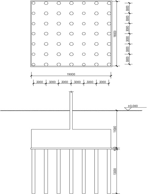
The dimensions of the foundation are 19.0 m, 19.0 m, and 20.0 m in the X, Y, and Z directions respectively. The CFG piles have a diameter of 0.80 m and a spacing of 3.0 m, arranged in a square pattern, and they are located at a depth of 7.0 m-20.0 m from the bottom of the model. Their length is 13.0 m each while the center of side pile is located at a distance of 0.50 m from the edge of foundation. The mattress has a thickness of 0.40 m and is situated at a depth of 20.0 m to 20.4 m from the bottom of the model. Eight-node hexahedral elements are used for both foundation and mattress layers while cylindrical grid elements are employed for CFG piles. A total number of 11809 units and 18442 nodes are established, as shown in Fig. 1(a).
Fig. 1Modeling
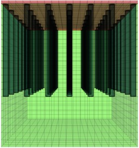
a) Solid model
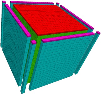
b) Boundary condition
2.2. Constitutive model and parameter values
The foundation soil consists of rubber particle loess, while the loess foundation is used for comparison purposes. The mattress is composed of graded gravel, and both the foundation soil and mattress are modeled using the More-Coulomb model with parameter values provided in Table 1.
Table 1Basic parameters
Position | Soil designation | Density (kg/m3) | Cohesive force (kPa) | Internal friction angle (°) | Modulus of compression Es (MPa) | Poisson’s ratio μ |
Original foundation | Rubber particle loess | 1870 | 17 | 23 | 17 | 0.25 |
Original foundation | Loess | 1920 | 16 | 21 | 12 | 0.25 |
Mattress layer | Graded gravel | 2000 | 1 | 40 | 35 | 0.2 |
Taking 5 times the compression modulus of Young’s modulus into account, the volume modulus (K) and shear modulus (G) of rubber particle loess are calculated using Eqs. (1-2) [24], respectively. The obtained values are K=56.5 MPa and G=34 MPa. In addition, for the mattress material, the volume modulus is determined to be K=97.2 MPa, while the shear modulus is found to be G=72.9 MPa:
where: E is Young’s modulus, E=5ES.
The CFG pile is composed of C20 concrete, which follows an elastic constitutive model. With a density of 2500 kg/m3, Young's modulus of 25.5 GPa, and Poisson’s ratio of 0.2, the internal friction angle and cohesion of the concrete are determined using Eqs. (3-4) [25]. Given σc=13.4 MPa and σt=1.54 MPa for C20 concrete, its internal friction angle φ is calculated to be 52.5° while the cohesion c amounts to 2.271 MPa. Consequently, the bulk modulus K is estimated at 14.2 GPa with a shear modulus G of approximately 10.6 GPa:
where: σc – standard value of compressive strength of concrete (MPa); σt – standard tensile strength of concrete (MPa):
where: c – cohesive force of concrete (MPa).
2.3. Contact surface setting
The cohesion and internal friction angle of the structural plane between the pile and soil are 0.8 times that of the soil, resulting in c=13.6 kPa and an internal friction angle of 18.4°. The contact surface 1 between the pile and non-pile is established using the guiding method, with parameters kn and ks selected as 10 times Eq. (5), yielding a result of 2.83×10¹¹ Pa. The tensile stiffness at the pile-soil interface is assumed to be zero, with no residual strength after failure occurs between the pile and soil. The contact surface 2 is established between the foundation and mattress using a shift-to-remove method, with parameters identical to those used for contact surface 1:
where: ∆zmin – the minimum size in the normal direction of adjacent elements (m).
2.4. Boundary condition
The static calculation is subject to displacement constraints on the four vertical sides of x=0, x=19.0, y=0, and y=19.0, fixed constraints at the bottom of the model, and free constraints at the top of the mattress. For dynamic calculation, the original static boundary conditions at the bottom of the model are eliminated and replaced with static boundary conditions and free field boundaries considering infinite extension of foundation soil on each side, as shown in Fig. 1(b).
2.5. Loading
In the static calculation, a vertical static loading of 450 kPa is applied to the top surface of the mattress. In the dynamic calculation, the dynamic loading is applied by utilizing a stress time history, while taking into account the p-wave velocity Cp determined using Eq. (6):
The normal stress is calculated according to Eq. (7), resulting in a value of –7.4×10⁵ Pa. Considering the dynamic loading as a positive basalt wave with a frequency f of 1 Hz, its expression is shown in Eq. (8):
where: vn – normal velocity component on model boundary:
where: σnA= –8.7×10⁵ Pa.
2.6. Damping condition
The mechanical damping in this study is implemented using Rayleigh damping, with a minimum critical damping ratio of 0.5 % and the center frequency set as the natural vibration frequency. Fig. 2 illustrates the displacement time-history curve obtained by considering the natural vibration frequency. As shown in the figure, the natural vibration period is determined to be 0.343 s, corresponding to a natural vibration frequency of 2.92 Hz.
Fig. 2The curve of displacement time history for natural frequency calculation
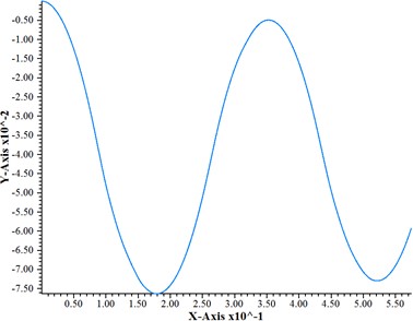
Fig. 3The maximum unbalanced force
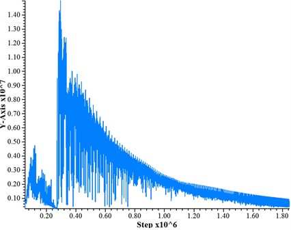
Assuming self-weight consolidation occurs between the pile and soil following pile construction, the model conducts 5,000 steps of consolidation calculation under self-weight loading. Subsequently, it applies the superstructure load to calculate an additional 50,000 steps after stabilization of pile-soil consolidation before performing dynamic calculations. The dynamic calculation time is set at 0.1 s, and Fig. 3 illustrates the distribution curve of maximum unbalanced forces, indicating a high level of convergence.
3. Analysis
3.1. Change of vertical displacement
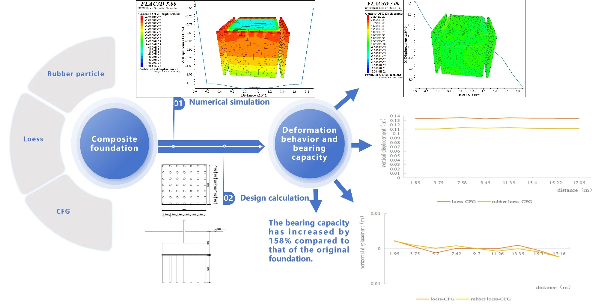
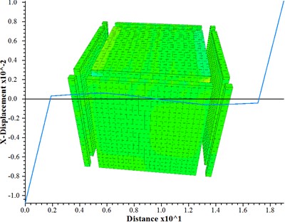
The settlement of the foundation under dynamic loading can be observed from Fig. 4, which increases with depth and exhibits a strip distribution. This indicates that deeper focal depth results in less damage to the building’s foundation. Notably, the maximum displacement value at the top of the mattress is not located in its middle but around its center, aligning with CFG treatment for road subgrades [26]. With a significant magnitude of 11.35 cm, this maximum displacement is considerably larger than the settlement of the pile-soil composite foundation (As shown in Fig. 5), suggesting substantial settlement within the mattress itself. The primary reason behind this lies in the absence of loading sharing effects from piles within the mattress; instead, it solely bears loading transmitted by buildings and experiences settlement influenced by its modulus and thickness [27], [28].
Fig. 4The vertical displacement at the top of the mattress
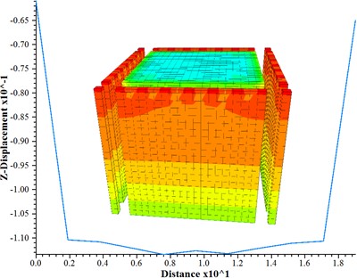
Fig. 5The vertical displacement curve at the top of mattress and piles
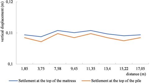
As depicted in Fig. 5, at identical positions, settlements within mattress surpass those within piles, indicating considerable compression deformation occurring specifically within these mattress alongside overall settlement. Consequently, while mattresses can adjust pile-soil stress ratios to some extent, they also represent weak links within composite foundations. Therefore, it is imperative to consider the reinforcement of mattress properties in order to enhance their overall quality.
3.2. Change of horizontal displacement
As shown in Fig. 6, the horizontal displacement at the center of the mattress is nearly zero, while on its left and right sides it is positive and negative respectively. The displacements on both sides are almost equal with a maximum value of approximately 4.22 mm, indicating that the dynamic loading causes compression towards the center of the mattress. Similarly, as shown in Fig. 7, the horizontal displacement at the top of pile-soil composite foundation near its middle is also close to zero but negative on one side and positive on another side with a maximum value of about 1.2 mm. The symmetry between both sides suggests that under dynamic loading conditions, there is movement in all directions from the center at the top of pile-soil composite foundation.
The horizontal displacement of the mattress remains zero within the range of 5.0 m-14.8 m, accounting for approximately 51.6 % of the total length of the model. Similarly, the horizontal displacement of the pile top is zero within the range of 1.80 m-17.20 m, constituting around 81 % of the total length of the model. Consequently, in designing CFG composite foundation, it is recommended to extend the piles by at least 0.23 times wider than the foundation loading range. At the same time, considering mattress stability, an extension by 0.9 times wider than that should be considered for mattresses as well. However, considering the actual situation, when extending mattress by such proportions since it would significantly increase construction scope multiple-fold and correspondingly escalate costs and construction duration accordingly, thus making it relatively challenging to extend mattress ranges extensively. The mattress plays a crucial role in determining failure mechanisms for composite foundations subjected to dynamic loading.
Fig. 6The horizontal displacement at the top of mattress
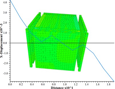
Fig. 7The horizontal displacement at the top of composite foundation composed of piles and soil
4. Comparison of settlement under static and dynamic loading
In addition to the parameters shown in Table 1, the design incorporates additional parameters as follows. The foundation is buried at a depth of 11.0 m, with a saturated weight of 19.5 kN/m3 for the foundation soil. The pile length is 13.0 m and is distributed in a square pattern, as shown in Fig 8. The bearing capacity reduction coefficient for each individual pile is set at 0.85, while the reduction coefficient for soil bearing capacity between piles is determined as 0.95. The standard values assigned to ultimate side resistance and ultimate end resistance of each pile are respectively 60 kPa and 1400 kPa. A single pile exhibits a bearing capacity of 1300 kN under axial compression conditions, considering that the vertical loading amounts to be approximately 450 kPa.
Fig. 8Simplified diagram of Lizheng geotechnical calculation
According to the calculation of Lizheng software, the characteristic value of the bearing capacity for the modified composite foundation is 516.5 kPa, exhibiting a remarkable increase of 158 % compared to that of the original foundation with a bearing capacity of 200 kPa. The stress area method is employed to calculate the settlement of the foundation, considering a current compression modulus value of 23.77 MPa and an experience coefficient for settlement calculation is 0.312. Consequently, the total settlement at the center of the composite foundation amounts to 4.614 cm < 5.0 cm, meeting design requirements and affirming that this design effectively meets static loading demands.
The maximum vertical displacement of the rubber particle loess-CFG, including the mattress, under dynamic loading is 11.08 cm, which exceeds the allowable settlement value of 5.0 cm under static loading. Part of this settlement is primarily attributed to the compression deformation of the mattress. Therefore, careful consideration should be given to selecting appropriate materials and thickness for the mattress as well as other parameters for the rubber particle loess-CFG under dynamic loading [29], [30]. Furthermore, it should be noted that different mattress thicknesses result in significant variations in settlement behavior of the composite foundation [31].
5. Deformation comparison between rubber particle loess-CFG and loess-CFG
The dynamic response characteristics of the loess-CFG are determined through numerical simulation of a composite foundation consisting of loess and CFG piles under various load conditions using the same method. Fig. 9 illustrates the displacement distribution curves at the top of the mattress for both rubber particle loess-CFG and loess-CFG subjected to dynamic loading. The results indicate that, on average, the vertical displacement of rubber particle loess-CFG is approximately 17.0 % smaller than that of loess-CFG at different positions. The horizontal displacement amplitudes are similar on both sides of the model for both types of piles. However, in the middle section, rubber particle loess-CFG exhibit smaller maximum displacements compared to loess-CFG with a more moderate variation. Therefore, rubber particle loess-CFG has strong seismic stability.
The incorporation of rubber particles reduces soil porosity, enhances particle connectivity, alters soil structure, and improves its resistance to deformation. Moreover, the high elasticity of rubber particles can effectively attenuate dynamic loading and mitigate soil deformation and failure under such conditions.
Fig. 9Rubber loess – CFG and loess – CFG Mattress top displacement
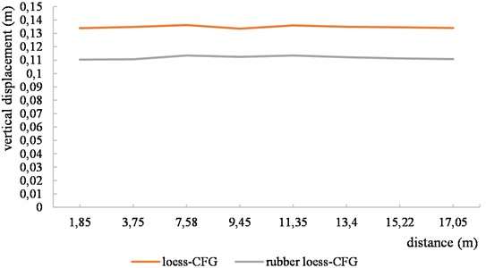
a) Vertical displacement
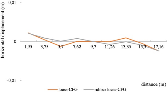
b) Horizontal displacement
6. Conclusions
1) The vertical displacement of the rubber particle loess-CFG gradually decreases from bottom to top and exhibits a strip distribution when subjected to dynamic loading at the base of the model. Consequently, in practical applications, as the focal depth increases, the impact of dynamic loading on composite foundation deformation diminishes, while the influence of earthquakes on composite foundation deformation becomes closely associated with the focal depth.
2) The vertical compression and deformation of the mattress of the rubber particle loess-CFG result in significant settlement. Horizontally, the mattress is squeezed towards the middle part, and the soil between the piles move in all directions from the center at the top of pile-soil composite foundation. Moreover, both the horizontal displacement of the mattress and its variation range are considerably larger than those of soil between the piles.
3) The deformation of rubber particle loess-CFG is minimal under static loading, however, it significantly increases under dynamic loading. It is crucial to consider the deformation of the mattress in design and analyze the material and thickness of the mattress to mitigate its influence.
4) The vertical and horizontal displacements at the top of the loess-CFG with rubber particles are observed to be smaller than those of the loess-CFG pile under dynamic loading conditions. This indicates that incorporating rubber particles can enhance the seismic stability and improves the foundation’s ability to withstand earthquakes.
5) CFG piles enhances the bearing capacity of the foundation through the strengthening effect of the piles, and the incorporation of rubber particles improves the seismic performance of the soil, so the rubber particles loess-CFG has the dual effect of increasing the strength of the foundation and resisting dynamic deformation.
References
-
He Zhiqiang et al., “Experimental study of engineering properties of loess reinforced by lignosulfonate,” (in Chinese), Rock and Soil Mechanics, Vol. 38, No. 3, pp. 731–739, 2017, https://doi.org/10.16285/j.rsm.2017.03.015
-
Dong Chaofan et al., “Experimental study on the shear strength of lignin fiberlmproved loess,” (in Chinese), Safety and Environmental Engineering, Vol. 29, No. 2, pp. 102–110, 2022, https://doi.org/10.13578/j.cnki.issn.1671-1556.20210510
-
Liu Zhaozhao et al., “Water holding capacity and water stability of lignin-modified loess,” (in Chinese), Chinese Journal of Rock Mechanics and Engineering, Vol. 39, No. 12, pp. 2582–2592, 2020, https://doi.org/10.13722/j.cnki.jrme.2020.0416
-
W. Liu, J. Wang, G. Lin, L. Wen, and Q. Wang, “Microscopic mechanism affecting shear strength in lignin-treated loess samples,” Advances in Materials Science and Engineering, Vol. 2019, pp. 1–12, May 2019, https://doi.org/10.1155/2019/7126040
-
Q. Wang, J. Wang, X. Zhong, H. Ma, and X. Xu, “Dynamic nonlinear and residual deformation behaviors of the fly ash-modified loess,” Shock and Vibration, Vol. 2021, pp. 1–11, Dec. 2021, https://doi.org/10.1155/2021/1306986
-
Z. Luo, X. Zhang, Y. Gao, Y. Wang, F. Liu, and X. Lan, “Mechanical properties of loess subgrade treated by superabsorbent polymer,” Case Studies in Construction Materials, Vol. 18, p. e01741, Jul. 2023, https://doi.org/10.1016/j.cscm.2022.e01741
-
J. Bai, Y. Zhang, and S. Wu, “Review study of physical and mechanical characteristics on mixed soil with scrap tire rubber particles,” Jordan Journal of Mechanical and Industrial Engineering, Vol. 14, No. 1, pp. 71–79, 2020.
-
L. Zhe, D. Xinchao, and L. Dongyang, “Experimental study on unconfined compressive strength of loess mixed with rubber particles,” (in Chinese), Construction Engineering Technology and Design, No. 2, p. 443, 2020.
-
C. Jinchun, M. Lingfeng, and Z. Benke, “Soft soil improvement and optimization with CFG columns,” (in Chinese), Soil Engineering and Foundation, Vol. 35, No. 5, pp. 544–548, 2021.
-
N. Wang et al., “Comparative analysis of bearing capacity of CFG single pile by centrifugal model tests and field tests,” (in Chinese), Chinese Journal of Geotechnical Engineering, Vol. 44, No. S2, pp. 6–10, 2022.
-
W. Shuai, Z. Jinbao, and T. Jianxing, “Analysis of some problems in design of CFG pile foundation treatment,” (in Chinese), Building Structure, Vol. 51, No. S1, pp. 1879–1882, 2021.
-
S. Guangli and F. Jianyang, “Bearing capacity numerical simulation and field test of CFG pile composite foundation,” (in Chinese), Journal of Jilin Jianzhu University, Vol. 38, No. 4, pp. 27–31, 2021.
-
Zhao Xiongfei., “Research on the settlement effect of CFG pile composite foundation on bridge head foundation,” (in Chinese), Transpoworld, No. 12, pp. 60–61, 2022, https://doi.org/10.16248/j.cnki.11- 3723/u.2022.12.053
-
Li Xuejun and Zeng Jixiang., “Settlement monitoring and FLAC 3D simulation analysis of soft soil subgrade treated with CFG pile,” (in Chinese), Construction and Design for Project, No. 3, pp. 125–127, 2023, https://doi.org/10.13616/j.cnki.gcjsysj.2023.02
-
Bi Junwei, Gao Guangyun, and Geng Jianlong, “Vibration mitigation characteristics of CFG pile-supported transversely isotropic subgrade under high-speed train loading,” (in Chinese), Journal of Vibration and Shock, Vol. 42, No. 4, pp. 116–125, 2023, https://doi.org/10.13465/j.cnki.jvs.2023.04.014
-
He Chunyu., “Research on dynamic response of CFG pile composite foundation road bridge transition section,” (in Chinese), Transpoworld, Vol. 32, pp. 78–81, 2022, https://doi.org/10.16248/j.cnki.11-3723/u. 2022.32.025
-
L. Wei, Z. Chuner, and W. Jiawu, “Refined three-dimensional numerical analysis of the influence of loading on CFG pile-net composite foundation,” (in Chinese), Transposition Science and Technology, Vol. 312, No. 3, p. 11, 2022.
-
G. Peicheng, “Application of CFG pile composite foundation in high-rise structures,” (in Chinese), Sichuan Architecture, Vol. 42, No. 3, pp. 207–208, 2022.
-
L. Min, “Calculation and correction of pile-soil stress ratio of CFG pile composite foundation under embankment,” (in Chinese), Hebei Journal of Industrial Science and Technology, Vol. 38, No. 1, pp. 50–56, 2021.
-
Dang Yujing, “A discussion on the adjustment factor of seismic bearing capacity for CFG-pile composite foundation,” (in Chinese), Industry Building, Vol. 50, No. 11, pp. 97–101, 2020, https://doi.org/10.13204/j.gyjzg19090330
-
Yu Zipeng et al., “Study on seismic dynamic response of CFG pile-supported reinforced embankment in liquefied soil,” (in Chinese), Building Structure, Vol. 52, pp. 2544–2549, 2022, https://doi.org/10.19701/j.jzjg.22s2273
-
H. Zhang, L. Liu, W. Feng, Y. Zhou, W. Zheng, and B. Zhao, “Design selection and dynamic response analysis of CFG pile composite foundation in soft soil areas,” Frontiers in Materials, Vol. 9, No. 9, Aug. 2022, https://doi.org/10.3389/fmats.2022.980375
-
Yang Chuanling and Xie Xiaoqin., “Numerical analysis on parameter sensitivity of soft soil subgrade strengthened by CFG pile,” (in Chinese), Journal of Xiangtan University (National Science Edition), Vol. 43, No. 2, pp. 95–102, 2021, https://doi.org/10.13715/j.cnki.nsjxu.2021.02.012
-
D. Song, F. Zhang, and X. Han, “Deformation analysis of slopes with soft and hard rock interbedding based on FLAC3D,” (in Chinese), Journal of Hebei Engineering University (Science Edition), Vol. 33, No. 2, pp. 86–90, 2016.
-
Y. Li, X. Ge, and C. Mi, “Rock soil concrete failure criteria and estimation of strength parameters,” (in Chinese), Journal of Rock Mechanics and Engineering, No. 5, pp. 770–776, 2004.
-
G. Song, P. Zhou, and Q. Hu, “Design of CFG pile mattress thickness,” (in Chinese), China sciencepaper, Vol. 16, No. 6, p. 592, 2021.
-
Hu Hao, “Study on influence of cushion parameters on bearing characteristics of CFG pile composite foundation,” (in Chinese), Urban Roads Bridges and Flood Control, Vol. 272, No. 12, pp. 159–162, 2021, https://doi.org/10.16799/j.cnki.csdqyfh.2021.12.045
-
J. Lai, H. Liu, J. Qiu, and J. Chen, “Settlement analysis of saturated tailings dam treated by CFG pile composite foundation,” Advances in Materials Science and Engineering, Vol. 2016, No. 1, pp. 1–10, Jan. 2016, https://doi.org/10.1155/2016/7383762
-
Zhao Fengguang, “Research on the application of CFG pile in railway soft soil roadbed,” (in Chinese), Western Transportation Technology, Vol. 177, No. 4, pp. 191–194, 2022, https://doi.org/10.13282/j.cnki.wccst.2022.04.058
-
Y. Yao, X. Zhang, and X. Liu, “Pile cap and cushion effect analysis of CFG pile composite foundation based on field test,” (in Chinese), Journal of Taiyuan University of Technology, 2022.
-
G. Wang and Z. Shen, “Research on the application of CFG pile composite foundation in karst landform areas,” (in Chinese), Architecture, Vol. 51, No. 9, pp. 1052–1054, 2020.
About this article

The authors would like to thank Inner Mongolia Autonomous Region Natural Science Foundation (2023LHMS05048) and Inner Mongolia Autonomous Region education science research “14th Five-Year Plan” project (NGJGH2023082) for this study.
The datasets generated during and/or analyzed during the current study are available from the corresponding author on reasonable request.
Jian-Guang Bai is mainly responsible for funding acquisition, writing-original draft preparation, and software. Wen-Qi Kou is mainly responsible for data curation. Hai-Jun Li is mainly responsible for writing-review and editing.
The authors declare that they have no conflict of interest.
