Abstract
This paper deals with a dual design device for wind energy production, in which the movement of the blade consists of several stages, that is, two stages of rotation about two fixed axes and two stages of the blades straight translation movement. The proposed design offers a closed-shaped flattened conveyor equipped with several identical flat-shaped blades. The blades are mounted on a conveyor belt and have an opportunity to move together with the belt in one straight line direction. Therefore, air flow kinetic energy is transformed into translation motion of flat blades. The conveyor system has a built-in energy generator. To analyse blade interaction with air flow, a superposition principle is applied, in which the fast chaotic motion of air particles (Brownian motion) is separated from the slow flow motion with the given average velocity. On the base of such separation, a differential equation of motion for the entire conveyor system with one degree of freedom is obtained. Dynamics of the system due to the action of air flow is simulated with computer program Mathcad. Optimization of system parameters is performed, using a generated power as criterion. In addition, motion control at changeable airflow is optimized by selecting the blade orientation and corresponding adjustment of generator.
Highlights
- New design of wind energy production device made in the form of closed loop conveyor equipped with several flat blades is developed.
- Wind flow interaction with flat blade is studied using concept of zones (pressure and suction zones) for a rigid body immersed in an airflow.
- Optimization of system parameters is performed by computer simulation with program Mathcad, using a generated power as criterion.
- The developed conveyor type wind power plant has some important advantages in comparison with the existing wind equipment (smaller vertical dimensions, sufficiently reduced noise and vibration level, simplified technical service and repair).
1. Introduction
Wind energy is one of the most developed and widely applicable types of renewable green energies. Various types of methods and devices are used for energy extraction from air flow. Operation principle of existing wind energy conversion equipment is mainly based on air flow action on blades mounted on a special wheel and further transformation of air flow kinetic energy into the mechanical energy of wheel rotation [1], [2]. To increase power extraction from air flow, commercial wind turbines of such type are mainly made as large windmill-like structures with big radial dimensions of blades [3]. Besides, special optimization of blade shape and dimensions is necessary [4], [5].
The typical size of wind turbines, as shown in [6], [7], has grown dramatically over the last three decades. For example, to obtain a power of 13-15 MW, it is necessary to increase a length of blade up to 100 m and height of main supporting tower up to 200 m [8]. But for the relatively small towers with height of about 50-60 m, the generated power does not exceed 0.5-1 MW. As is known [9], the generated power increases as the square of the blade’s length. Due to this, in modern commercial wind generators, the speeds of blade ends increase significantly, reaching 80 m/s and more [10]. However, such a solution has a negative effect on the use of wind turbines due to high generated noise, increased vibration and dynamic stresses (especially, near the blades attachment to the rotor) resulted in damages and failure of wind turbines [11]. Besides, large radial configuration of existing blades gives the rise to significant vibration problems due to a decrease in the spectrum of resonant frequencies. To prevent accidental situations, different methods of nondestructive testing and condition monitoring techniques are used [12], [13]. This requires additional time and financial resources.
Besides, noise produced by wind power generators causes annoyance and mental stress in humans [14] as well these noises have negative affect on birds and animals [15], [16]. To decrease noise level, reduction of geometrical dimensions of blades and other elements of wind turbines would be useful. Besides, small-sized wind turbines (in contrast to the large-scale ones) can harness power in low wind speed conditions [17].
Due to the above-mentioned advantages of small-sized wind turbines, in recent years this direction of wind power engineering has been intensively developing. Several research works have been reported on small wind turbines design [18], [19] and performance optimization [20]-[22]. But in these devices, orientation of flat blades to the air flow is not optimal, and due to this, the potential possibilities for wind energy conversion are not fully used.
Investigation of rotating flat blade interaction with air flow is performed in [23]. New methods and devices for wind energy conversion with special regulation of blade’s turning angle are proposed in [24], [25]. The main disadvantage of these devices lies in the large number of blades. For example, it has argued in [26] that operational efficiency of these devices is reduced with the increasing of number of blades. Specifically, for number of blades more than one, air vortexes are formed between the blades, which negatively affect the efficiency of wind energy conversion.
The present paper focuses on the elimination of shortcomings of existing wind equipment with rotating blades (big vertical dimensions, increased noise and vibration level) by the development of a small or medium wind power plant providing efficient conversion of air flow energy. To achieve this goal, it is proposed to realize in the wind device a new operational principle based on use of flat blades translational motion excited by air flow.
2. Materials and methods
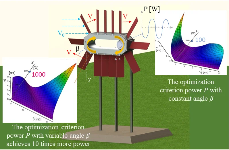
A new design of wind power plant synthesized on the base of a closed-shaped flattened conveyor equipped with flat-shaped blades is shown in Fig. 1.
Fig. 1Three-dimensional design of wind power plant (horizontal displacement of belt)
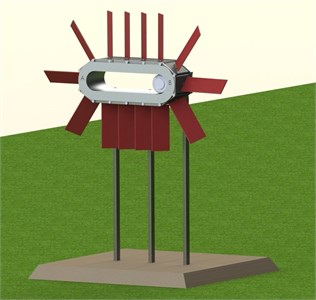
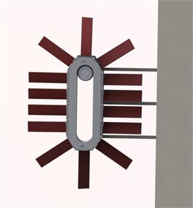
Fig. 2Three-dimensional design of wind power plant (vertical displacement of belt)
The conveyor belt is equipped with several identical wind interaction receiving blades, which move together in one straight line direction, then turn in the reversing mechanism by 180 degrees and move in the opposite direction. The conveyor system has a built-in energy generator. The drive shaft of the generator can be mounted on one of the axes of the reversing ends of the conveyor belt (in Fig. 1 the drive shaft is mounted on the right end of the conveyor).
The conveyor can be placed both horizontally and at any angle to the horizon. The model of wind power plant with belt vertical displacement is shown in Fig. 2.
Principal model of the wind power plant synthesized on the base of a closed belt conveyor is shown in Fig. 3.
Closed belt conveyor 1 forms a central part of the plant, besides belt has an ability to move parallel to coordinate plane . The conveyor is driven by an air flow with velocity , acting on the blades 2 in parallel to the axis.
Power is obtained from a generator connected with rotor 3 at the one end (left or right) of the conveyor 1 (Fig. 3). The flat blades 2 are attached tightly to the conveyor 1 with a rigid fastening element 4 (welded hinge). Besides, the blades 2 are fixed at the angle toward the -axis. The model of generator has several flat blades 2. Due to the action of air flow , translation motion of blades 2 along conveyor’s straight and circular sections (in final turns) is excited. To obtain useful power, this translation motion of blades 2 is transformed into the rotation of generator’s rotor 3.
Fig. 3Principle model of air flow power plant on the base of belt conveyor: 1 – closed belt conveyor; 2 – flat blade; 3 – rotor; 4 – rigid fastening element
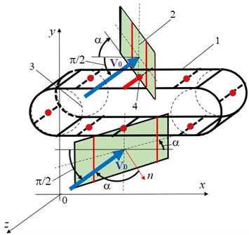
Fig. 4Model of air flow interaction with one moving thin blade
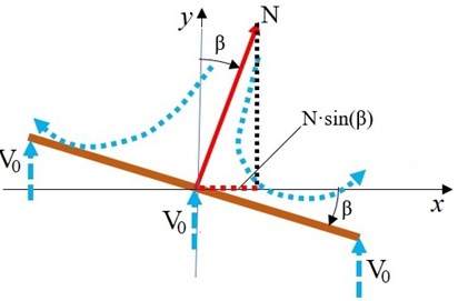
Conveyor with one degree of freedom was presented by differential equation of blade translation motion described in previous paper [27]. In this case, we would like to present motion analysis for the generator with polynomial resistance force, for which the equation of generalized force composed by authors is:
where is a parameter of dry friction force, is a coefficient of viscous damping in linear generator, is a coefficient of polynomial resistance force of generator, is a generalized coordinate, is a velocity of a respective coordinate. Parametric optimization of the proposed wind power plant can be performed by the variation of generator parameters and . For example, by the increasing of parameter from 2 till 20 kg·s-1, it has become possible to reduce in twice a maximal velocity of blade translation motion (from 14 till 7 m/s) and simultaneously to increase sufficiently a power generated by wind installation (from 400 till 1000 W). Meanwhile, by the changing of angle from /3 to /8, the generated power is increased approximately in 10 times (from 100 to 1000 W).
Therefore, optimization of generated power P on the variation of blades turning angle was done as presented in Fig. 5-6, where parametric optimization problems are solved with the aid of program Mathcad. First example of response surface for the criterion power as a function of blade turning angle and its translational velocity is shown in Fig. 5 (air flow velocity is constant 10 m/s). This optimization problem mathematically is formulated as follows:
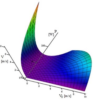
Other example of response surface for the optimization criterion power is shown in Fig. 6. In solution of this problem, search on optimum is held in the field of parameters and (under the constant turning angle 0,707 rad). This optimization problem mathematically is formulated as follows:
Fig. 5Response surface for the optimization criterion P as a function of blade turning angle β and velocity V (for the case of air flow velocity V0= 10 m/s)
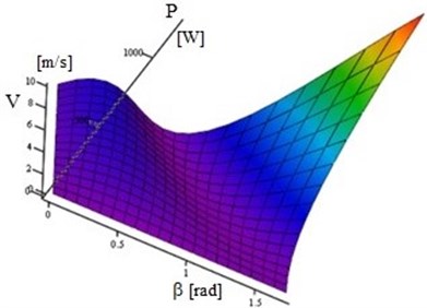
Fig. 6Response surface for the optimization criterion P as a function of air flow velocity V0 and blade velocity V (for the case of blade turning angle β= 0,707 rad)
Optimization procedure realized by the variation of blade velocity was performed as follows:
Optimization procedure realized by the variation of blade position angle was performed as:
Optimization procedure realized by the variation of air flow velocity was performed as:
Optimal zones on the response surfaces (Fig. 5 and Fig. 6) corresponding to the maximal generated power are shown with red color.
3. Results and discussions
1) The study is performed using a new model of wind and blade interaction, which the authors themselves have developed in recent years [25], [27]. This method is based on the application of pressure and suction zones without the use of experimental lift and drag coefficients. The applicability of this method is confirmed by experiments with physical models of air flow devices in Armstrong Subsonic wind tunnel (the results of experiments are included in the paper [28]).
2) The paper proposes a new wind device with the dual-action flat blade motion, in which the main energy extraction from the air flow takes place in a straight-line motion stage of the conveyor.
3) The interaction of air flow with a rotating flat blade is not considered here, because such interaction has been studied earlier (i.e., in [24]) as well in the analysis of windmills operation.
4) The operational advantage of the proposed conveyor-type wind device lies in the fact that velocities of all points of the lateral surface of flat blade are the same and usually don’t exceed 10-20 m/s (as opposed to conventional rotary-type wind devices, in which the speeds of the blade ends are sufficiently higher and reach 80 m/s and more [10]). This makes it possible to use the side surface of the blade more effectively than in known rotary devices [8], [9]. Besides, due to relatively low blades motion velocity, noise and stresses in the blade material are reduced sufficiently.
5) Vertical dimension of the proposed conveyor-type wind device usually doesn’t exceed 3-5 m (in contrast to commercial rotary wind turbines, which vertical dimensions reach 200 m and more [8]). Thanks to this, technical diagnostics, service and repair of the proposed device is simplified sufficiently.
6) The evaluation of generated power by the proposed device is obtained in the work. As it is followed from the computer simulation results, one flat blade of one square meter area at a wind flow of 10 m/s can generate power of about 400 till 1000 W. For 10 blades it will be from 4000 till 10 000 W. This power is approximately equivalent to the power of small wind devices with rotating blades (1-12 kW) [8].
4. Conclusions
New design of wind energy conversion device made in the form of closed loop conveyor equipped with several flat blades is developed. Blades are mounted on a conveyor belt and have an opportunity to move together with the belt in one straight line direction. Operation principle of the device is based on utilization of flat blades translation and rotation motion due to the interaction with air flow.
Air flow interaction with flat blade that performs translation motion was studied using concept of zones (pressure and suction zones) for a rigid body immersed in an air flow. Dynamic analysis of thin blade interaction with air flow is performed by computer simulation with program Mathcad. A detailed experimental validation of the simulation results, using physical model the proposed wind device, will be the subject of future research.
Optimization of system parameters is performed, using a generated power as criterion. But the interaction constants of the braking generator, as well as the constants of the conveyor system and blades orientation were used as the variable parameters in the optimization task. In accordance with the simulation results, a power generated by the proposed air flow device (from 4 till 10 kW) is approximately equivalent to the power of small wind devices with rotating blades [8]. But the developed conveyor type wind power plant has some important advantages in comparison with the existing wind equipment (smaller vertical dimensions, sufficiently reduced noise and vibration level, simplified technical service and repair). Further efficiency improvement of the conveyor type wind power plant can be achieved by the blade shape optimization.
References
-
D. J. de Renzo, Wind Power: Recent Developments. Park Ridge, New Jersey, USA: Noyes Data Corporation, 1979.
-
Le Gourieres Desire, Wind Power Plants. Theory and Design. Pergamon Press, 1982.
-
D. Micallef and G. van Bussel, “A review of urban wind energy research: aerodynamics and other challenges,” Energies, Vol. 11, No. 9, p. 2204, Aug. 2018, https://doi.org/10.3390/en11092204
-
J. Allen, E. Young, P. Bortolotti, R. King, and G. Barter, “Blade planform design optimization to enhance turbine wake control,” Wind Energy, Vol. 25, No. 5, pp. 811–830, May 2022, https://doi.org/10.1002/we.2699
-
J.-J. Chattot, “Optimization of wind turbines using helicoidal vortex model,” Journal of Solar Energy Engineering, Vol. 125, No. 4, pp. 418–424, Nov. 2003, https://doi.org/10.1115/1.1621675
-
I. Al-Bahadly, Wind Turbines. Croatia: IntechOpen, 2011.
-
Gasch R. and Twele J., Wind Power Plants. New York: Springer, 2012.
-
G. Edwar Mehanny Beshay and K. Yousef Maalawi, “Structural Optimization of Wind Turbine Blades for Improved Dynamic Performance,” Design Optimization of Wind Energy Conversion Systems with Applications, pp. 69–107, Apr. 2020, https://doi.org/10.5772/intechopen.91643
-
Kulunk E., “Fundamental and Advanced Topics in Wind Power,” in Aerodynamics of Wind Turbines, InTech, 2011, pp. 3–18, https://doi.org/10.5772/731
-
M. Ragheb and A. M. Ragheb, “Wind turbines theory – the Betz equation and optimal rotor tip speed ratio,” in Fundamental and Advanced Topics in Wind Power, InTech, 2011, pp. 19–38.
-
C. Boller and M. Buderath, “Fatigue in aerostructures where structural health monitoring can contribute to a complex subject,” Philosophical Transactions of the Royal Society A: Mathematical, Physical and Engineering Sciences, Vol. 365, No. 1851, pp. 561–587, Feb. 2007, https://doi.org/10.1098/rsta.2006.1924
-
C. C. Ciang, J.-R. Lee, and H.-J. Bang, “Structural health monitoring for a wind turbine system: a review of damage detection methods,” Measurement Science and Technology, Vol. 19, No. 12, p. 122001, Dec. 2008, https://doi.org/10.1088/0957-0233/19/12/122001
-
A. Friedmann, D. Mayer, M. Koch, and T. Siebe, “Monitoring and damage detection in structural parts of wind turbines,” in Fundamental and Advanced Topics in Wind Power, InTech, 2011, pp. 207–232.
-
S. E. Ambrose, R. W. Rand, and C. M. E. Krogh, “Wind turbine acoustic investigation,” Bulletin of Science, Technology and Society, Vol. 32, No. 2, pp. 128–141, Apr. 2012, https://doi.org/10.1177/0270467612455734
-
L. D. Knopper and C. A. Ollson, “Health effects and wind turbines: A review of the literature,” Environmental Health, Vol. 10, No. 1, pp. 1–10, Dec. 2011, https://doi.org/10.1186/1476-069x-10-78
-
J.-K. Park and Y. Do, “Wind turbine noise behaviorally and physiologically changes male frogs,” Biology, Vol. 11, No. 4, p. 516, Mar. 2022, https://doi.org/10.3390/biology11040516
-
H. Muhsen, W. Al-Kouz, and W. Khan, “Small wind turbine blade design and optimization,” Symmetry, Vol. 12, No. 1, p. 18, Dec. 2019, https://doi.org/10.3390/sym12010018
-
R. K. Singh and M. R. Ahmed, “Blade design and performance testing of a small wind turbine rotor for low wind speed applications,” Renewable Energy, Vol. 50, pp. 812–819, Feb. 2013, https://doi.org/10.1016/j.renene.2012.08.021
-
M. K. Chaudhary and A. Roy, “Design and optimization of a small wind turbine blade for operation at low wind speed,” World Journal of Engineering, Vol. 12, No. 1, pp. 83–94, Feb. 2015, https://doi.org/10.1260/1708-5284.12.1.83
-
L. Scappatici, N. Bartolini, F. Castellani, D. Astolfi, A. Garinei, and M. Pennicchi, “Optimizing the design of horizontal-axis small wind turbines: From the laboratory to market,” Journal of Wind Engineering and Industrial Aerodynamics, Vol. 154, pp. 58–68, Jul. 2016, https://doi.org/10.1016/j.jweia.2016.04.006
-
S. Sanaye and A. Hassanzadeh, “Multi-objective optimization of airfoil shape for efficiency improvement and noise reduction in small wind turbines,” Journal of Renewable and Sustainable Energy, Vol. 6, No. 5, p. 053105, Sep. 2014, https://doi.org/10.1063/1.4895528
-
D. A. Umar, C. T. Yaw, S. P. Koh, S. K. Tiong, A. A. Alkahtani, and T. Yusaf, “Design and optimization of a small-scale horizontal axis wind turbine blade for energy harvesting at low wind profile areas,” Energies, Vol. 15, No. 9, p. 3033, Apr. 2022, https://doi.org/10.3390/en15093033
-
J. Viba, V. Beresnevich, S. Noskovs, and M. Irbe, “Investigations of rotating blade for energy extraction from fluid flow,” Vibroengineering Procedia, Vol. 8, pp. 312–315, Oct. 2016.
-
J. Viba, V. Beresnevich, M. Irbe, and J. Dobelis, “The control of blades orientation to air flow in wind energetic device,” Energy Procedia, Vol. 128, pp. 302–308, Sep. 2017, https://doi.org/10.1016/j.egypro.2017.08.317
-
J. Viba, V. Beresnevich, and M. Irbe, “Synthesis and optimization of wind energy conversion devices,” in Design Optimization of Wind Energy Conversion Systems with Applications, IntechOpen, 2020, pp. 125–141, https://doi.org/10.5772/intechopen.90819
-
A. Eltayesh et al., “Experimental and numerical investigation of the effect of blade number on the aerodynamic performance of a small-scale horizontal axis wind turbine,” Alexandria Engineering Journal, Vol. 60, No. 4, pp. 3931–3944, Aug. 2021, https://doi.org/10.1016/j.aej.2021.02.048
-
I. Tipans, J. Viba, M. Irbe, and S. K. Vutukuru, “Analysis of non-stationary flow interaction with simple form objects,” Agronomy Research Journal, Vol. 17, pp. 1227–1234, 2019, https://doi.org/10.15159/ar.19.083
-
J. Viba, V. Beresnevich, and M. Irbe, “Methods and devices for wind energy conversion,” in Wind Turbines – Advances and Challenges in Design, Manufacture and Operation, IntechOpen, 2022, https://doi.org/10.5772/intechopen.103120
