Abstract
Traditional cavity reinforcement technology is difficult to effectively protect the cavity from damage caused by modern large-yield explosions, and the anti-explosion performance of prestressed anchor cables needs to be improved urgently. The design of a new prestressed high-elastic fully adhesive anchor cable for the enhancement of the anti-explosion effects of the anchor cable is presented in this paper. A constitutive model of the anchor cable is established in FLAC 3D and used to restore an equal scale field anti-explosion test. The reinforcement effects of the new anchor cable are compared with the conventional one’s. Results show that the stresses of the anchor cables differ at different locations: the anchor cable at the arch crown of the cavern is the one mainly under pressure with the compressive strain of the new anchor cable reduced by 25 %; while the anchor cable at the arch foot of the cavern is the one mainly under tension and the tensile strain of the new anchor cable is reduced by 26.3 %. The vertical displacement of the arch crown is reduced by 16.2 % with the reinforcement of the new anchor cable. The new anchor cable performs much better on the reinforcement of the cavern than the conventional one in the aspects of stress, strain and displacement, which provides a basis for the design of new anchor cables and their applications in engineering.
Highlights
- A new type of prestressed high-elastic anchor cable is formed by adding a high-elastic spring element inside the anchor head of a conventional fully adhesive anchor cable.
- The secondary development of the constitutive model of this new anchor cable was carried out using FLAC 3D software, and the validity of this model was demonstrated with the field test data.
- Compared to the conventional anchor cable, the compressive strain of the new anchor cable reduces by 25%, and the tensile strain of the new anchor cable reduces by 26.3%.
- As to the anchor cable reinforcement effect, the vertical displacement of the arch crown with the new anchor cable reduces by 16.2%.
1. Introduction
A large number of national defense works are underground cavern works. With the widespread use of high-powered weapons, these works must have higher strengths of resistance to underground explosion strikes [1-4]. However, it is difficult to stand to the damages of facilities with traditional reinforcement techniques from modern large-equivalent explosion loads. Therefore, it is of great practical importance to propose studies on new anchor cables with high-strength reinforcement abilities [5-8]. The prestressed anchor cable is developed based on the reinforcement of regular anchor cable [9]. To improve the anti-explosion ability of the prestressed anchor cable reinforced cavern, the prestressed anchor cable is designed using the new high-elastic elements in the head of the anchor cable in this paper. Combined with a fully cement-imbedded anchor cable, which is most commonly used in actual projects, a new prestressed high-elastic fully adhesive anchor cable is formed. There are already former studies [10, 11] conducted for the reinforcement mechanism of various anchor cables on caverns using FLAC 3D. And this paper also uses FLAC 3D to establish the constitutive model of the new anchor cable. The validity of the numerical simulation is verified comparing to the field explosion resistance test results. And on this basis, the reinforcement differences between the new and the conventional anchor cables with different explosion loads are analyzed, which provides a basis for the application of prestressed high-elastic fully adhesive anchor cables in engineering.
2. Principle and simulation method of the new anchor cable
2.1. Principle of the high-elastic anchor
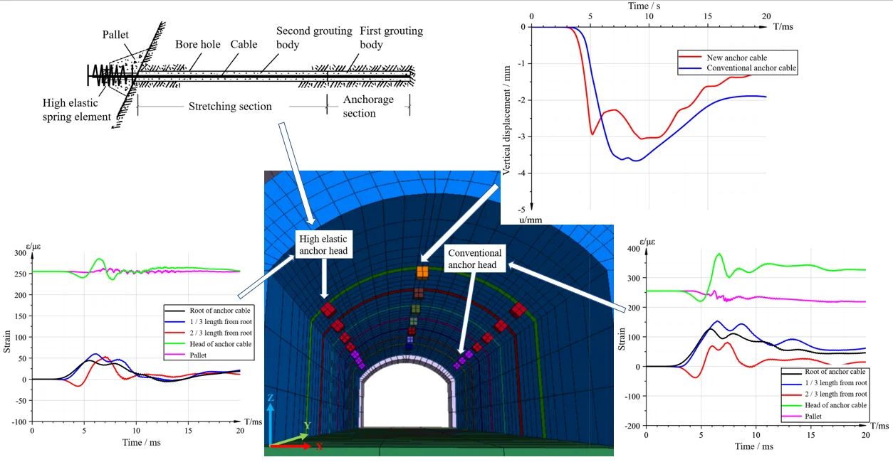
The fully adhesive anchor cable (hereinafter referred to as the conventional anchor cable) is an anchor cable widely used and effectively performed in the reinforcement process of cavern works [9]. Single conventional anchor cable is mainly composed of anchor cable body, anchor head, pallet, grouting body, etc. On this basis, adding a high-elastic spring element in the anchor head of the conventional anchor cable makes the new fully adhesive anchor cable (hereinafter referred to as the new anchor cable), the structure of which is shown in Fig. 1.
The load-bearing performance of the new anchor cable is affected by the high-elastic element. When the element is subjected to the first stage of axial compressive force, its displacement is directly proportional to the force. If the axial compressive force is above 200 kN, the displacement arises little, which is called as locked state in engineering and serves to limit further displacements.
Fig. 1The structure of the new anchor cable

2.2. Secondary development of the constitutive model of the anchor head
The corresponding anchor head unit test analysis model is built in FLAC 3D using cube model with the side length of 200 mm. The vertical displacement at the bottom of the model is constrained, and vertical loading at a uniform speed is carried out on the model surface for the simulation of the loading process of the pressure tester as shown in Fig. 2(a). Comparing the calculation results with the test results, a constitutive model and parameters describing the mechanical behavior of the anchor head are obtained. The main method to get the bilinear deformation characteristics in numerical calculations is changing the elastic modulus of the simulation unit. Establishing the variable elastic constitutive model in the calculation makes the original element able to act as a bilinear elastic deformation in the process of compression. When the high-elastic element is compressed, the strain increases together with the stress, and when the strain is greater than 0.20, the elastic modulus of the calculated model unit is extremely high, so that the strain of the unit no longer rises and the displacement of the high-elastic element is simulated with no more increase as the locked-state shown in Fig. 2(b).
Fig. 2The anchor head unit analysis model
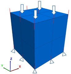
a) The calculation model of the anchor head unit
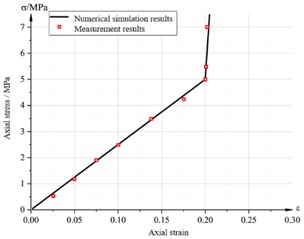
b) Comparison of measured values and simulation results of the high-elastic element
3. Numerical simulation and analysis
3.1. Numerical model establishment
According to the test site conditions, a full-scale mountain model is established using FLAC 3D, with the size of 24 m ×15 m × 25 m. As shown in Fig. 3(a), there are seven cross sections in the model. Each cross section is arranged with one anchor cable at the arch crown and two anchor cables at the arch foot. Cross sections 1-4 are set with the highly-elastic anchor head, while 5-7 with the conventional ones. The explosion center is right above the arch crown of the 4th cross section and the radius of the explosion cavity is 0.5 m. The parameters of the rock and anchor head are shown in Table 1, and the anchor cable parameters are shown in Table 2.
Table 1The parameters of the rock and anchor head
Material | Elastic Modulus (GPa) | Poisson’s ratio | Density (kg/m3) | Cohesive force (MPa) | Friction angle (°) | Tensile strength (MPa) |
Rock | 30 | 0.25 | 2500 | 0.8 | 40 | 3 |
Anchor head | 32.5 | 0.2 | 2500 | 1.0 | 45 | 2 |
Table 2The basic anchor cable parameters
Grouting materials | Cross-sectional area of anchor cable (m2) | Density (kg/m3) | Cohesive force (MN/m) | Strength per unit length of mortar ((N/m)/m) | Outer circumference of mortar (m) | Internal friction angle (°) | Yield strength (kN) |
Conventional mortar | 1.96×10⁻³ | 2500 | 1.57 | 6.5×10⁹ | 0.377 | 30 | 780 |
Flexible mortar | 1.96×10⁻³ | 2500 | 2.0 | 2.0×10⁹ | 0.377 | 30 | 780 |
Field tests are conducted on the cavern using the new and conventional anchor cables for reinforcement. Groups are established based on the types of the anchor heads in the horizontal direction along the depth direction of the cavern (i.e., Y direction of the model), as shown in Fig. 3(b). The input dynamic load is shown in the time stress curve generated by 50 kg TNT-equivalent explosive calculated by CONWEP.
Fig. 3Numerical model diagram
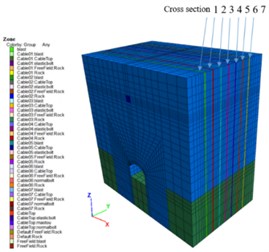
a) The establishment of model
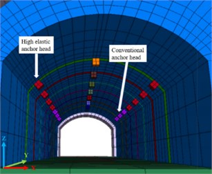
b) Anchor head elements in the cavern
3.2. Numerical calculation validity verification
The field anti-explosion test measured acceleration curve is shown in Fig. 4(a), while the acceleration curve obtained by numerical calculations at the same location is shown in Fig. 4(b). The field measured peak acceleration is 79 g, while the peak acceleration by numerical calculation is 80 g, which certifies that the two accelerations are basically the same.
The strain curve of the new anchor cable at the 1/3 length from the anchor root of the cable is field measured as shown in Fig. 5(a). The two curves remain a good consistency in the numerical magnitude and strain curve development trend. Fig. 5(b) shows the strain curve of the new anchor cable at the arch foot of the reinforced cavern. The numerical calculation result is also close to the field measured one. The comparison of the acceleration and strain illustrate the validity of the numerical model calculation.
Fig. 4Comparison of the accelerations at the arch crown of the cavern
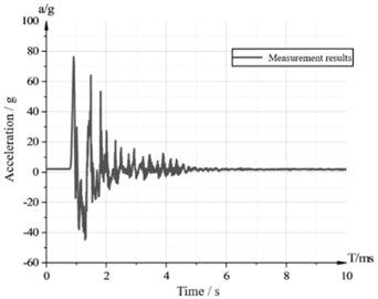
a) Field measured acceleration time history curve
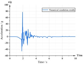
b) Numerical calculation of the acceleration time curve
Fig. 5Comparison of the measured and calculated strain values of the high-elastic fully adhesive anchor cable
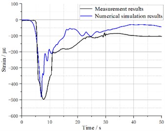
a) Comparison of the strains of the anchor cables at the arch crown of the cavern
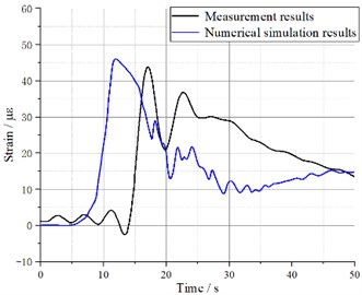
b) Comparison of the strains of the anchor cables at the arch foot of the cavern
4. Protective characteristics of the new anchor cable
Numerical simulation and comparison on the conventional and new anchor cables are carried out to find out the advantages of the new anchor cable. Explosive loads are both set to 2.5 GPa and the prestressing forces are 100 kN. With different reinforcement situations of the anchor cables, the comparison of the strain curves at the arch crown and foot of the cavern are implemented and the test results of vertical displacements at the arch crown of the cavern are recorded.
4.1. Anchor cable strains at the arch crown
The two anchor cable strain curves at the arch crown are shown in Fig. 6. There is a peak compressive stress on the root of the anchor cable firstly, and then the rest parts of the anchor cable gets compressed. With the distance increasing from the root of the anchor cable, the peak compressive strain gradually decreases. A tensile strain at the anchor cable head is generated due to the downward deformation of the rock at the arch crown of the cavern. It reaches its peak value around the head of the anchor cable of the cavern. The maximum compressive strain for conventional anchor cable is 800 με while the maximum compressive strain of the new one is 600 με, a 25 % reduction compared to the conventional one. It certifies that the new anchor cable is mainly subjected to compressive stress at the arch crown near the center of the explosion, and its compressive stress reduces effectively.
Fig. 6Different anchor cable strain curves at the arch crown
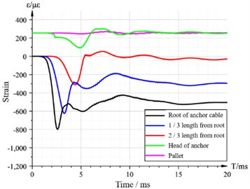
a) The strain curve of the conventional anchor cable
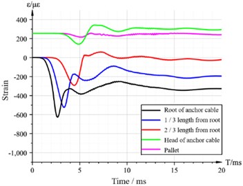
b) The strain curve of the new anchor cable
4.2. Anchor cable strains at the arch foot
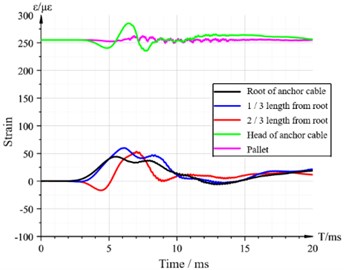
The two anchor cables strains generated at the arch foot are numerically and significantly smaller than the strains at the arch crown, both of which are mostly in tension. The peak tensile strains of the anchor cables are at the anchor head: the peak tensile strain of the conventional anchor cable is 380 με, while the peak tensile strain of the new anchor cable is 280 με, 26.3 % less than that of the conventional one. So it is obvious that the new anchor cable shows a better tensile performance.
Fig. 7Different anchor cable strain curves at the arch foot
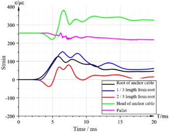
a) The strain curve of the conventional anchor cable
b) The strain curve of the new anchor cable
4.3. Vertical displacement at the arch crown
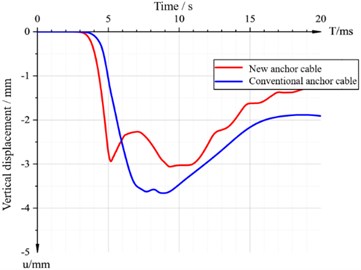
The vertical displacement time curves of the arch crown with two different anchor cables are shown in Fig. 8. The peak vertical displacement of the arch crown with the conventional anchor cable is 3.7 mm while it is 3.1 mm with the new anchor cable, a 16.2 % reduction compared to the conventional one. And the residual displacement of the new anchor cable is significantly smaller than that of the conventional one. It certifies that the new anchor cable with the elastic elements performs better in reducing displacement and reinforcing the cavern effectively.
Fig. 8Comparison of the vertical displacements at the arch crown
5. Conclusions
In this paper, a new type of high-elastic anchor cable is developed based on the conventional anchor cable commonly used in engineering projects by adding high-elastic element into the anchor head of the anchor cable. A variable elastic constitutive model in FLAC 3D is established, and the simulation results fit well with the strain characteristics of the high-elastic element in engineering projects. And then a numerical model of the same proportion with the field explosion test is established. It shows that the strains and the curve development trends of the measured and the calculated results are basically the same, which certifies the validity of the numerical model.
With the peak explosion load of 2.5 GPa and the prestressing force of 100 kN, the anchor cable at the arch crown near the explosion center is the one mainly subjected to the compressive stress. Compared to the conventional anchor cable, the compressive strain of the new anchor cable reduces by 25 %. The anchor cable at the arch foot is the one mainly subjected to the tensile stress. Compared with the conventional anchor cable, the tensile strain of the new anchor cable reduces by 26.3 %. As to the anchor cable reinforcement effect, the vertical displacement of the arch crown with the new anchor cable reduces by 16.2 %, and the residual displacement is smaller, which certifies the reinforcement effect of the new anchor cable.
References
-
W.-B. Lu, P. Li, M. Chen, C.-B. Zhou, and D.-Q. Shu, “Comparison of vibrations induced by excavation of deep-buried cavern and open pit with method of bench blasting,” Journal of Central South University, Vol. 18, No. 5, pp. 1709–1718, Oct. 2011, https://doi.org/10.1007/s11771-011-0892-2
-
P. C. Xu, Q. Dong, X. P. Li, and Y. Luo, “Influence research of underground caverns blasting excavation on excavation damage zone of adjacent cavern,” Advanced Materials Research, Vol. 838-841, pp. 901–906, Nov. 2013, https://doi.org/10.4028/www.scientific.net/amr.838-841.901
-
S. Gu, B. Jiang, G. Wang, H. Dai, and M. Zhang, “Occurrence mechanism of roof-fall accidents in large-section coal seam roadways and related support design for Bayangaole Coal Mine, China,” Advances in Civil Engineering, Vol. 2018, pp. 1–17, Jul. 2018, https://doi.org/10.1155/2018/6831731
-
W. Yu and F. Liu, “Stability of close chambers surrounding rock in deep and comprehensive control technology,” Advances in Civil Engineering, Vol. 2018, pp. 1–18, Aug. 2018, https://doi.org/10.1155/2018/6275941
-
Z. Huang, E. Broch, and M. Lu, “Cavern roof stability-mechanism of arching and stabilization by rockbolting,” Tunnelling and Underground Space Technology, Vol. 17, No. 3, pp. 249–261, Jul. 2002, https://doi.org/10.1016/s0886-7798(02)00010-x
-
Q. Qian and X. Zhou, “Failure behaviors and rock deformation during excavation of underground cavern group for Jinping I hydropower station,” Rock Mechanics and Rock Engineering, Vol. 51, No. 8, pp. 2639–2651, Aug. 2018, https://doi.org/10.1007/s00603-018-1518-x
-
Q. Jiang, X.-T. Feng, J. Cui, and S.-J. Li, “Failure mechanism of unbonded prestressed thru-anchor cables: in situ investigation in large underground caverns,” Rock Mechanics and Rock Engineering, Vol. 48, No. 2, pp. 873–878, Mar. 2015, https://doi.org/10.1007/s00603-014-0574-0
-
B. Jiang et al., “The research of design method for anchor cables applied to cavern roof in water-rich strata based on upper-bound theory,” Tunnelling and Underground Space Technology, Vol. 53, pp. 120–127, Mar. 2016, https://doi.org/10.1016/j.tust.2016.01.015
-
F. L. Zhan and P. Ye, “Construction techniques and mechanism of pre-anchoring fissured stope Hangingwall by fully-grouted cable bolts,” Applied Mechanics and Materials, Vol. 580-583, pp. 283–286, Jul. 2014, https://doi.org/10.4028/www.scientific.net/amm.580-583.283
-
J. J. Wang, Y. J. Wang, and C. Y. Guo, “Application of numerical simulation in reinforcement of caverns underground by external cross-anchoring,” Advanced Materials Research, Vol. 852, pp. 835–839, Jan. 2014, https://doi.org/10.4028/www.scientific.net/amr.852.835
-
S. Zuo and X. Wang, “Numerical simulation and evaluation of construction process on large-scale underground plants,” in 2010 Asia-Pacific Power and Energy Engineering Conference, No. 2, pp. 1–4, 2010, https://doi.org/10.1109/appeec.2010.5449295
About this article
This research was supported by the General Program of National Natural Science Foundation of China (Item No. 52179101).

