Abstract
In this work, effect of fin tip temperature on the rate of heat transfer and thermal efficiency of a rectangular convective-radiative fin with temperature-dependent thermal conductivity is analyzed using differential transformation method. The results of the power series solutions are verified numerically, and very good agreements are established. Also, the symbolic solutions are used to examine the effects of the conductive-convective and nonlinear thermal conductivity parameters on the thermal performance of the passive device. It is found that when the nonlinear thermal conductivity parameter increases, the fin tip temperature increases. However, the temperature at the tip of the fin decreases as the conductive-convective parameter increases. The thermal efficiency of the fin increases as the fin tip temperature and nonlinear thermal conductivity parameters are augmented but an increase conductive-convective parameter causes the fin tip temperature and the thermal efficiency of the extended surface to reduce. An increase in the conductive-convective parameter causes decrease the temperature distribution and thermal efficiency in the passive device. However, the efficiency of the fin increases as the nonlinear thermal conductivity parameter increases. When nonlinear thermal conductivity and conductive-convective parameters increase, the rate of heat transfer at the fin base increases. The developed analytical solutions provide a good platform for the nonlinear thermal analysis of the fin and proper design of the extended surfaces in thermal systems.
1. Introduction
The enhancements of heat transfer by the use of fins in thermal and electronic systems serve the prime purpose of effective cooling of the engineering and industrial equipment [1]. Such an important applications has provoked so many research works [2-18], just to mention a few. In the bid of theoretical investigations, the thermal damage problems and heat transfer enhancement by the extended surfaces, the controlling thermal models of the passive devices are always nonlinear. Although, there are various approximate analytical and numerical solutions that have been used to solve the thermal problems [6-26], the quest for further studies is increasing demanded. In a recent work, Darvishi et al. [27] studied steady state thermal performance in convective-radiative porous radial fin while in the same year, Hoshyar [28] adopted homotopy perturbation method to developed series solution to steady state thermal performance longitudinal porous fins with variable internal heat generation. In the following year, Sobamowo [29] applied Galerkin’s method of weighted residual to some simple but highly accurate analytical solutions for thermal performance of rectangular fin with variable internal heat generation and thermal conductivity. Also, with the use of various approximate analytical methods, the effects of magnetic field on the steady state thermal performance of solid and porous fins were explored by Hashar et al. [30], Oguntala et al. [31], Patel and Meher [32]. Additionally, Sobamowo [33] examined the optimum design and thermal performance of a cooling fin under convective and radiative heat transfer using finite element method.
The review of the past studies shows that the analytical study of nonlinear transient heat transfer analysis in extended surfaces have not extensively been presented in literature. Moreover, the obvious advantages of generating analytical solutions to the nonlinear problems are very much important. Such solutions provide proper physical insights and effective predictions of the thermal performance of the extended surface. Also, the analytical approach of differential transformation method reduces the complex mathematical analysis, high computational cost and time. Additional to the best of the authors’ knowledge, the exploration of the effect of fin tip temperature on the rate of heat transfer and thermal efficiency of a fin has not been presented in literature. Therefore, the present work applies differential transformation method to examine the effect of temperature at the tip of the fin on the rate of heat transfer and thermal efficiency of a rectangular convective fin with temperature-dependent thermal conductivity. Also, the symbolic solutions are used to examine the effects of the conductive-convective and nonlinear thermal conductivity parameters on the thermal performance of the passive device.
2. Problem formulation
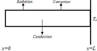
Consider a longitudinal straight fin with variable thermal conductivity and exposed on both faces to a convective-radiative environment at temperature and heat transfer co-efficient as in Fig. 1. Assuming that the extended surface isotropic, homogeneous and with constant thermo-physical properties. It is taken that the heat transfer is one-dimensional along the length of the fin. The prime surface is perfectly in thermal contact with the base of the fin and there is no heat gain or loss through the tip of the fin.
Thermal energy equation based on model assumptions is expressed as:
where the temperature-dependent thermal conductivity is expressed as a linear law:
Fig. 1Schematic of longitudinal fin
Therefore, Eq. (1) can be written as:
The boundary conditions are:
When negligible temperature difference exists between fin base and fin tip, the term in Eq. (3) could be expressed as a linear function of temperature as:
On substituting Eq. (6) into Eq. (3), we have:
On introducing the following dimensionless parameters in Eq. (8) into Eq. (7):
we arrived at the dimensionless forms of the governing as follows:
On expanding Eq. (9), we have:
and the dimensionless boundary conditions are:
3. Method of solution: differential transform method
The above governing differential equation is highly nonlinear, and such nonlinearity imposes some difficulties in the development of exact analytical method to generate closed form solution for the equation. Therefore, in this work, differential transformation method is used. The differential transformation method maps a governing equation into an algebraic domain and then obtain an inversion using a series summation method. This approximate analytical method generates solution with the controlling parameters adequately conserved.
The basic definitions of the method can be found in Moradi et al. [19]. However, the differential transformations of some functions are presented as follow:
1. If , then for all .
2. If , then .
3. If , then .
4. If , then .
5. , then .
6. If , then .
7. If , then .
8. If , then .
9. If , then .
10. If , then .
11. , then .
12. , then .
13. If , then .
14. If , then .
15. , then .
16. , then .
17. , then .
4. Solution of the nonlinear differential transformation method
The differential transform of the dimensionless governing of equation in Eq. (10) is:
Which can be simplified further as:
where:
From the boundary conditions, one can write differential transforms:
From the differential transform of the governing equation, we have:
From the definition of DTM, we have the solution of:
here, the constant is determined from the terminal boundary conditions as:
5. Heat transfer rate in the fin
The rate of heat transfer through the fin is given as:
The dimensionless heat transfer rate is given as:
Substituting Eq. (16) into Eq. (19), we have:
The rate of heat transfer at the base of the fin 1:
6. Thermal efficiency of the fin
The quantity of heat dissipated form the fin can be written as:
The maximum heat dissipated form the fin can be expressed as:
Therefore, the thermal efficiency of the fin is given as:
After applying Eqs. (6) and (8) to Eq. (24), the thermal efficiency of the fin can be expressed in dimensionless form as:
On substituting Eq. (16) into Eq. (25), after integrating the resulting equation, we have:
In order to verify the results of the present work, the nonlinear model was also solved numerically using finite difference method. The finite difference scheme for the nonlinear thermal model in Eq. (10) is:
While for the boundary conditions are:
From Eq. (19), the finite difference of the rate of heat transfer from the fin can be written as:
From Eq. (25), one can write the finite difference of the thermal efficiency as:
7. Results and discussion
The developed power series solutions which are presented in the previous section are simulated with the aid of MATHEMATICA. Also, the symbolic solutions are used to examine the effects of the conductive-convective and nonlinear thermal conductivity parameters on the thermal performance of the passive device as shown in Figs. 2-6. However, Table 1 shows the comparison of the results of the results of DTM and FDM. It shows that DTM provides good agreements with the results of the numerical method.
Table 1Comparison of results
FDM | DTM | |FDM-DTM| | |
0.0000 | 0.867912 | 0.867912 | 0.000000 |
0.2000 | 0. 872763 | 0.872762 | 0.000001 |
0.4000 | 0.887512 | 0.887511 | 0.000001 |
0.6000 | 0.912773 | 0.912772 | 0.000001 |
0.8000 | 0.949668 | 0.949668 | 0.000000 |
1.0000 | 1.000000 | 1.000000 | 0.000000 |
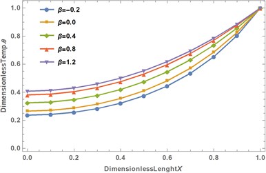
The effects of conductive-convective and nonlinear thermal conductivity parameters on the tip temperature of the fin are shown in Table 2. It is shown that when the nonlinear thermal conductivity parameter increases, the fin tip temperature also increases. However, the fin tip temperature decreases as the conductive-convective parameter increases.
Table 2Effects of nonlinear thermal conductivity and convective parameters on the dimensionless tip temperature
(Tip temperature) | ||
1 | –0.2 | 0.60417 |
1 | 0.0 | 0.64805 |
1 | 0.4 | 0.71605 |
1 | 0.8 | 0.76438 |
1 | 1.2 | 0.79964 |
1 | 1 | 0.78333 |
1 | 2 | 0.84673 |
2 | –0.2 | 0.23687 |
2 | 0.0 | 0.26580 |
2 | 0.4 | 0.32443 |
2 | 0.8 | 0.38078 |
2 | 1.2 | 0.43268 |
2 | 1 | 0.40743 |
2 | 2 | 0.51961 |
3 | –0.2 | 0.08812 |
3 | 0.0 | 0.09934 |
3 | 0.4 | 0.12613 |
3 | 0.8 | 0.15387 |
3 | 1.2 | 0.18456 |
3 | 1 | 0.16840 |
3 | 2 | 0.25000 |
4 | –0.2 | 0.03301 |
4 | 0.0 | 0.03667 |
4 | 0.4 | 0.04723 |
4 | 0.8 | 0.06123 |
4 | 1.2 | 0.07136 |
4 | 1 | 0.06702 |
4 | 2 | 0.08987 |
Tables 3 depict the impacts of fin tip temperature, conductive-convective and nonlinear thermal conductivity parameters on the thermal efficiency of the rectangular fin. The table shows that the thermal efficiency of the fin increases as the fin tip temperature and nonlinear thermal conductivity parameters are augmented. However, an increase conductive-convective parameter causes the fin tip temperature and the thermal efficiency of the fin to reduce.
Table 3Effects of nonlinear thermal conductivity and convective parameters on the dimensionless tip temperature and efficiency for β= –0.2 to 0.2
1 | 0.544452 | 0.64805 | 0.590776 | 0.68501 | 0.629962 | |
2 | 0.23687 | 0.249533 | 0.26580 | 0.276327 | 0.29528 | 0.302383 |
3 | 0.08812 | 0.156813 | 0.09934 | 0.170802 | 0.11227 | 0.186138 |
4 | 0.118420 | 0.03667 | 0.125771 | 0.04133 | 0.135573 | |
5 | 0.01254 | 0.096811 | 0.01358 | 0.100752 | 0.01492 | 0.106018 |
6 | 0.00483 | 0.083083 | 0.00510 | 0.085161 | 0.00542 | 0.087526 |
7 | 0.00190 | 0.073960 | 0.00196 | 0.074685 | 0.00203 | 0.075718 |
8 | 0.00077 | 0.067905 | 0.00078 | 0.067624 | 0.00070 | 0.052991 |
9 | 0.00032 | 0.063126 | 0.00032 | 0.063083 | 0.00033 | 0.064163 |
10 | 0.00014 | 0.059395 | 0.00014 | 0.058893 | 0.00014 | 0.060066 |
Table 4Effects of nonlinear thermal conductivity and convective parameters on the dimensionless tip temperature and efficiency for β= 0 to 0.8
1.0 | 0.64805 | 0.59078 | 0.71605 | 0.66318 | 0.76438 | 0.71579 |
1.5 | 0.42510 | 0.39208 | 0.49878 | 0.45963 | 0.56102 | 0.51685 |
2.0 | 0.26580 | 0.27633 | 0.32443 | 0.32710 | 0.38078 | 0.37346 |
2.5 | 0.16308 | 0.21064 | 0.20379 | 0.24852 | 0.24578 | 0.28284 |
3.0 | 0.09934 | 0.17080 | 0.12613 | 0.20113 | 0.15387 | 0.22605 |
3.5 | 0.06037 | 0.14451 | 0.07756 | 0.17036 | 0.09617 | 0.19184 |
4.0 | 0.03667 | 0.12577 | 0.04723 | 0.14770 | 0.06123 | 0.17233 |
4.5 | 0.02230 | 0.11177 | 0.02831 | 0.12904 | 0.03904 | 0.15866 |
5.0 | 0.01358 | 0.10075 | 0.01672 | 0.11318 | 0.02351 | 0.14096 |
5.5 | 0.00830 | 0.09206 | 0.00983 | 0.10033 | 0.01295 | 0.11797 |
6.0 | 0.00510 | 0.08516 | 0.00581 | 0.09030 | 0.00704 | 0.09962 |
6.5 | 0.00315 | 0.07941 | 0.00347 | 0.08245 | 0.00396 | 0.08767 |
7.0 | 0.00196 | 0.07469 | 0.00211 | 0.07693 | 0.00230 | 0.07933 |
7.5 | 0.00123 | 0.07077 | 0.00130 | 0.07244 | 0.00138 | 0.07387 |
8.0 | 0.00078 | 0.06762 | 0.00081 | 0.06843 | 0.00084 | 0.06865 |
8.5 | 0.00050 | 0.06505 | 0.00051 | 0.06465 | 0.00053 | 0.06640 |
9.0 | 0.00032 | 0.06308 | 0.00033 | 0.06310 | 0.00033 | 0.06101 |
9.5 | 0.00021 | 0.05973 | 0.00022 | 0.06397 | 0.00022 | 0.06240 |
10.0 | 0.00014 | 0.05889 | 0.00014 | 0.05790 | 0.00014 | 0.05691 |
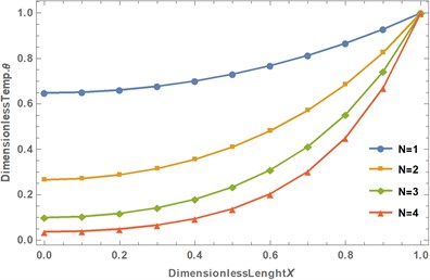
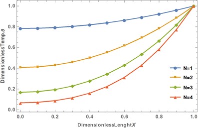
Fig. 2Effect of conductive-convective on the temperature distribution in the fin
a)
b)
The effects of conductive-convective parameter on the temperature distribution in the fin is shown in Figs. 2(a) and 2(b). It is shown that as the conductive-convective parameter increases, the fin temperature distribution in the passive device decreases which mean that the heat transfer rate through the fin is augmented and hence, the fin thermal efficiency is improved. This is because, as the convective heat transfer increases, there is more effective convective cooling which consequently lowers the temperatures in the fin. By extension, it could be stated that increasing in the values of conductive-convective parameter produces a decrease in the value of the fin efficiency. However, the efficiency of the fin increases as the nonlinear thermal conductivity parameter increases. It should be noted that the profile has steepest temperature gradient at lower value of the conduction-convection term, but its much higher value gotten from the lower value of thermal conductivity than the other values of convective parameter in the profiles produces a lower heat-transfer rate. This shows that the thermal performance or efficiency of the fin is favoured at low values of convective parameter since the aim (high effective use of the fin) is to minimize the temperature decrease along the fin length, where the best possible scenario is when everywhere. It must be pointed out that a small value of correspond to a relatively short and thick fins of poor thermal conductivity and high value of implies a long fin or fin with low value of thermal conductivity. Since, the thermal performance or efficiency of the fin is favoured at low values of convective fin parameter, very long fins are to be avoided in practice.
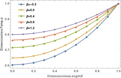
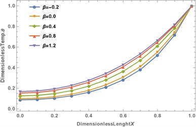
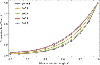
Fig. 3Effect of nonlinear thermal conductivity on the temperature distribution in the fin
a)
b)
c)
d)
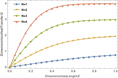
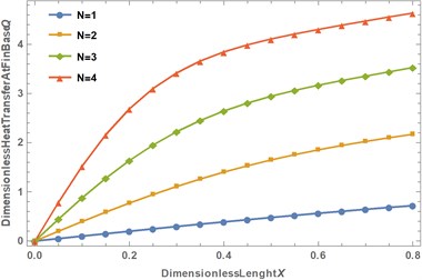
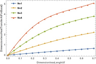
Fig. 4Effect of conductive-convective on the rate of heat transfer in the fin
a)
b)
c)
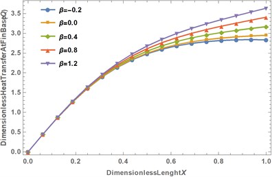
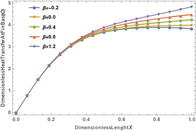
Figs. 3(a)-3(d) present the influence of the effect of nonlinear thermal conductivity paramter on temperature distributions in the fin. It should be noted that the positive value of the nonlinear thermal conductivity parameter implies fin materials whose thermal conductivity increases with increase in temperature while the negative value of the nonlinear thermal conductivity parameter corresponds to fin materials whose thermal conductivity decreases with increase in temperature. It can be inferred that the heat transfer rate through the fin increases as the nonlinear thermal conductivity parameter increases. This effect is as a result of the fact that the fin is able to transfer more heat due to increased thermal conductivity of the fin as the nonlinear thermal conductivity parameter increases.
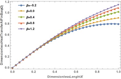
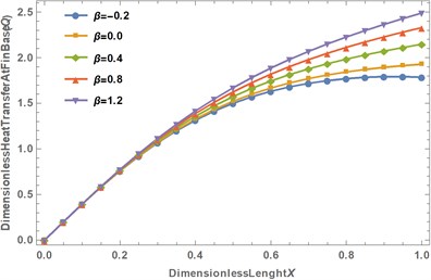
Fig. 5Effect of nonlinear thermal conductivity on the rate of heat transfer in the fin
a)
b)
c)
d)
Fig. 6Effect of nonlinear thermal conductivity on the efficiency in the fin
a)
b)
The influence of the nonlinear thermal conductivity and conductive-convective parameters on the rate of heat transfer at the base of the rectangular fin is shown in Figs. 4(a)-4(c) and 5(a)-5(d). The figure presents that the as nonlinear thermal conductivity and conductive-convective parameters increase, the rate of heat transfer at the fin base increases. This is due to the fact when the nonlinear thermal conductivity and conductive-convective parameters increase, the ability of the fin material to conduct heat to the fin base increases. When the nonlinear thermal conductivity parameter increases, the temperature-dependent thermal conductivity of the fin material becomes more sensitive to the fin temperature which causes an increase in the heat transfer rate in the fin.
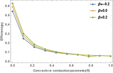
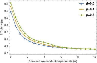
Fig. 6(a)-6(b) show the impact of the nonlinear thermal conductivity and conductive-convective parameters on the thermal efficiency of the longitudinal fin. From the figure, it is depicted that when the nonlinear thermal conductivity is increased, the thermal efficiency of the fin increases but an increase in the conductive-convective parameters causes the thermal efficiency of the fin to decrease.
8. Conclusions
In this work, effect of temperature at the tip of the fin on the rate of heat transfer and thermal efficiency of a rectangular convective fin with temperature-dependent thermal conductivity is analyzed using differential transformation method. The results of the approximate analytical solutions are verified numerically, and very good agreements are established. Also, the symbolic solutions are used for further parametric studies and the following results were established:
1) When the nonlinear thermal conductivity parameter increases, the fin tip temperature increases. However, the fin tip temperature decreases as the conductive-convective parameter increases.
2) The thermal efficiency of the fin increases as the fin tip temperature and nonlinear thermal conductivity parameters are augmented but an increase conductive-convective parameter causes the fin tip temperature and the thermal efficiency of the fin to reduce.
3) An increase in the conductive-convective parameter causes decrease the temperature distribution and thermal efficiency in the passive device. However, the efficiency of the fin increases as the nonlinear thermal conductivity parameter increases.
4) When nonlinear thermal conductivity and conductive-convective parameters increase, the rate of heat transfer at the fin base increases.
The developed analytical solution has given some physical insight into the thermal performance of the extended surfaces. The parametric study provides a good platform for proper design of the radiating fin for heat transfer enhancement in thermal systems.
References
-
S. Kiwan and M. A. Al-Nimr, “Using porous fins for heat transfer enhancement,” Journal of Heat Transfer, Vol. 123, No. 4, pp. 790–795, Aug. 2001, https://doi.org/10.1115/1.1371922
-
S. Kiwan, “Effect of radiative losses on the heat transfer from porous fins,” International Journal of Thermal Sciences, Vol. 46, No. 10, pp. 1046–1055, Oct. 2007, https://doi.org/10.1016/j.ijthermalsci.2006.11.013
-
S. Kiwan, “Thermal analysis of natural convection porous fins,” Transport in Porous Media, Vol. 67, No. 1, pp. 17–29, Mar. 2007, https://doi.org/10.1007/s11242-006-0010-3
-
S. Kiwan and O. Zeitoun, “Natural convection in a horizontal cylindrical annulus using porous fins,” International Journal of Numerical Methods for Heat and Fluid Flow, Vol. 18, No. 5, pp. 618–634, Jun. 2008, https://doi.org/10.1108/09615530810879747
-
R. S. R. Gorla and A. Y. Bakier, “Thermal analysis of natural convection and radiation in porous fins,” International Communications in Heat and Mass Transfer, Vol. 38, No. 5, pp. 638–645, May 2011, https://doi.org/10.1016/j.icheatmasstransfer.2010.12.024
-
B. Kundu and D. Bhanja, “An analytical prediction for performance and optimum design analysis of porous fins,” International Journal of Refrigeration, Vol. 34, No. 1, pp. 337–352, Jan. 2011, https://doi.org/10.1016/j.ijrefrig.2010.06.011
-
B. Kundu, D. Bhanja, and K.-S. Lee, “A model on the basis of analytics for computing maximum heat transfer in porous fins,” International Journal of Heat and Mass Transfer, Vol. 55, No. 25-26, pp. 7611–7622, Dec. 2012, https://doi.org/10.1016/j.ijheatmasstransfer.2012.07.069
-
A. Taklifi, C. Aghanajafi, and H. Akrami, “The effect of MHD on a porous fin attached to a vertical isothermal surface,” Transport in Porous Media, Vol. 85, No. 1, pp. 215–231, Oct. 2010, https://doi.org/10.1007/s11242-010-9556-1
-
D. Bhanja and B. Kundu, “Thermal analysis of a constructal T-shaped porous fin with radiation effects,” International Journal of Refrigeration, Vol. 34, No. 6, pp. 1483–1496, Sep. 2011, https://doi.org/10.1016/j.ijrefrig.2011.04.003
-
B. Kundu, “Performance and optimization analysis of SRC profile fins subject to simultaneous heat and mass transfer,” International Journal of Heat and Mass Transfer, Vol. 50, No. 7-8, pp. 1545–1558, Apr. 2007, https://doi.org/10.1016/j.ijheatmasstransfer.2006.08.029
-
S. Saedodin, S. Sadeghi, and S., “Temperature distribution in long porous fins in natural convection condition,” Middle-East Journal of Scientific Research, Vol. 13, No. 6, pp. 812–817, 2013.
-
S. Saedodin and M. Olank, “Temperature distribution in porous fins in natural convection condition,” Journal of American Science, Vol. 7, No. 6, pp. 476–481, 2011.
-
M. G. Sobamowo, A. A. Yinusa, O. P. Popoola, and M. A. Waheed, “Transient thermal analysis of convective-radiative moving fin under the influences of magnetic field and time-dependent boundary condition,” Computational Sciences and Engineering, Vol. 1, No. 2, pp. 139–152, 2021, https://doi.org/10.22124/cse.2021.20588.1019
-
M. Hatami and D. D. Ganji, “Thermal performance of circular convective-radiative porous fins with different section shapes and materials,” Energy Conversion and Management, Vol. 76, pp. 185–193, Dec. 2013, https://doi.org/10.1016/j.enconman.2013.07.040
-
M. Hatami and D. D. Ganji, “Thermal behavior of longitudinal convective-radiative porous fins with different section shapes and ceramic materials (SiC and Si3N4),” Ceramics International, Vol. 40, No. 5, pp. 6765–6775, Jun. 2014, https://doi.org/10.1016/j.ceramint.2013.11.140
-
M. Hatami, A. Hasanpour, and D. D. Ganji, “Heat transfer study through porous fins (Si3N4 and AL) with temperature-dependent heat generation,” Energy Conversion and Management, Vol. 74, pp. 9–16, Oct. 2013, https://doi.org/10.1016/j.enconman.2013.04.034
-
M. Hatami and D. D. Ganji, “Investigation of refrigeration efficiency for fully wet circular porous fins with variable sections by combined heat and mass transfer analysis,” International Journal of Refrigeration, Vol. 40, pp. 140–151, Apr. 2014, https://doi.org/10.1016/j.ijrefrig.2013.11.002
-
M. Hatami, G. R. Mehdizadeh Ahangar, D. D. Ganji, and K. Boubaker, “Refrigeration efficiency analysis for fully wet semi-spherical porous fins,” Energy Conversion and Management, Vol. 84, pp. 533–540, Aug. 2014, https://doi.org/10.1016/j.enconman.2014.05.007
-
A. Moradi, T. Hayat, and A. Alsaedi, “Convection-radiation thermal analysis of triangular porous fins with temperature-dependent thermal conductivity by DTM,” Energy Conversion and Management, Vol. 77, pp. 70–77, Jan. 2014, https://doi.org/10.1016/j.enconman.2013.09.016
-
S. Saedodin and M. Shahbabaei, “Thermal analysis of natural convection in porous fins with homotopy perturbation method (HPM),” Arabian Journal for Science and Engineering, Vol. 38, No. 8, pp. 2227–2231, Aug. 2013, https://doi.org/10.1007/s13369-013-0581-6
-
Ganji Dd and Hoshyar Ha, “Determination of Temperature Distribution for Porous Fin with Temperature-Dependent Heat Generation by Homotopy Analysis Method,” Journal of Applied Mechanical Engineering, Vol. 4, No. 1, 2015, https://doi.org/10.4172/2168-9873.1000153
-
S. R. Amirkolaei and H. Salarian, “Determination of temperature distribution for porous fin which is exposed to uniform magnetic field to a vertical isothermal surface by homotopy analysis method and collocation method,” Indian Journal of Scientific Research, Vol. 1, No. 2, pp. 215–222, 2014.
-
Y. Rostamiyan, D. Ganji, R. Petroudi, and K. Nejad, “Analytical investigation of nonlinear model arising in heat transfer through the porous fin,” Thermal Science, Vol. 18, No. 2, pp. 409–417, 2014, https://doi.org/10.2298/tsci111217103r
-
S. E. Ghasemi, P. Valipour, M. Hatami, and D. D. Ganji, “Heat transfer study on solid and porous convective fins with temperature-dependent heat generation using efficient analytical method,” Journal of Central South University, Vol. 21, No. 12, pp. 4592–4598, Dec. 2014, https://doi.org/10.1007/s11771-014-2465-7
-
R. Petroudi et al., “Semi-analytical method for solving non-linear equation arising of natural convection porous fin,” Thermal Science, Vol. 16, No. 5, pp. 1303–1308, 2012, https://doi.org/10.2298/tsci1205303p
-
S. Abbasbandy, E. Shivanian, and I. Hashim, “Exact analytical solution of forced convection in a porous-saturated duct,” Communications in Nonlinear Science and Numerical Simulation, Vol. 16, No. 10, pp. 3981–3989, Oct. 2011, https://doi.org/10.1016/j.cnsns.2011.01.009
-
M. T. Darvishi, R. Gorla, F. Khani, and A. Aziz, “Thermal performance of a porus radial fin with natural convection and radiative heat losses,” Thermal Science, Vol. 19, No. 2, pp. 669–678, 2015, https://doi.org/10.2298/tsci120619149d
-
H. A. Hoshyar, I. Rahimipetroudi, D. D. Ganji, and A. R. Majidian, “Thermal performance of porous fins with temperature-dependent heat generation via the homotopy perturbation method and collocation method,” Journal of Applied Mathematics and Computational Mechanics, Vol. 14, No. 4, pp. 53–65, Dec. 2015, https://doi.org/10.17512/jamcm.2015.4.06
-
M. G. Sobamowo, “Thermal analysis of longitudinal fin with temperature-dependent properties and internal heat generation using Galerkin’s method of weighted residual,” Applied Thermal Engineering, Vol. 99, pp. 1316–1330, Apr. 2016, https://doi.org/10.1016/j.applthermaleng.2015.11.076
-
H. A. Hoshyar, D. D. Ganji, and A. Majidian, “Least square method for porous fin in the presence of uniform magnetic field,” Journal of Applied Fluid Mechanics, Vol. 9, No. 2, pp. 661–668, Mar. 2016, https://doi.org/10.18869/acadpub.jafm.68.225.24245
-
G. Oguntala, R. Abd-Alhameed, and G. Sobamowo, “On the effect of magnetic field on thermal performance of convective-radiative fin with temperature-dependent thermal conductivity,” Karbala International Journal of Modern Science, Vol. 4, No. 1, pp. 1–11, Mar. 2018, https://doi.org/10.1016/j.kijoms.2017.09.003
-
T. Patel and R. Meher, “Thermal Analysis of porous fin with uniform magnetic field using Adomian decomposition Sumudu transform method,” Nonlinear Engineering, Vol. 6, No. 3, Jan. 2017, https://doi.org/10.1515/nleng-2017-0021
-
M. G. Sobamowo, “Optimum design and performance analyses of convective-radiative cooling fin under the influence of magnetic field using finite element method,” Journal of Optimization, Vol. 2019, pp. 1–19, Feb. 2019, https://doi.org/10.1155/2019/9705792
