Abstract
The purpose of this paper is to clarify the recommendations and to develop a methodology for calculating multi-piston pneumatic motors (pneumatic positioners) for analyzing the movement parameters of a pneumatic drive and taking into account the need for a smooth stop of the output rod. A system of differential equations is obtained, the solution of which gives a description of the dynamics processes occurring during the operation of a multi-piston pneumatic actuator. The software has been developed that allows to obtain a number of graphical dependencies, on the basis of which the designer decides on the expediency of using braking by the method of throttling the inputs and outputs of the pneumatic motor chambers.
1. Introduction
Pneumatic industrial robots (PIR) are still widely used to perform a wide range of lifting and transport operations, although they are currently being replaced by robots with an electric drive [1, 2]. It is believed that PIR are reliable and easy-to-operate, high-speed and low-cost robotic devices. PIR with a cyclic control system are characterized by high accuracy of the output to the desired point, but have a small number of positioning points. PIR with a positional system have a larger number of positioning points, but have less accuracy.
One of the ways to increase the number of positioning points in the cycle while maintaining high accuracy of the point output is the use of multi-piston pneumatic motors (pneumatic positioners). Multi-piston positioners are characterized by the need to dampen the movement of the output link of the drive at the end of the stroke (shock-free stop of the pistons at the end of the stroke), since at high speeds of movement of the output link when approaching the stops, strong impacts of the working body of the robot on the stops are possible. This worsens the dynamic characteristics of the drive, increases its operating time, and causes premature wear of the structure.
At the same time, the calculation of multi-piston pneumatic positioners has certain difficulties due to the fact that the internal pistons of the pneumatic motor do not have the properties of a rigid stop due to the pliability of the air, so the recommendations for the calculation of such pneumatic motors are of great practical importance.
In papers [3-10], methods for calculating robot pneumatic motors are given, in papers [11, 12] – methods for calculating the smooth stop of the piston at the end of the stroke for pneumatic motors with a single piston. However, the calculation of the smooth stop mode of a multi-piston engine has some features caused by the variable load on the pistons and many different combinations of movements of the piston groups, which cause difficulties in determining the parameters of the pneumatic drive.
2. Analytical dependencies for calculation
Consider a discrete-action N-piston drive operating on a differential principle. The scheme of such a drive for N= 3 is shown in Fig. 1.
Fig. 1N-discrete-action piston drive (N= 3)

Let’s introduce the state space C1,C2,…,CN, that characterizes the position of the pneumatic drive pistons:
where:Ci=1, if the i-th cavity is connected to the high-pressure line, the i-th piston is extended;Ci=0, if the i-th cavity is connected to the atmosphere, the i-th piston is retracted.
The variablesCi of the state space establish a one-to-one correspondence between the state of the distributor valves and the position of the pneumatic positioner pistons for the time periods when the transients in the drive have ended. The values of the variablesCi are assigned depending on the desired state of the motor output rod, which is conveniently set using binary code. Then the coordinate of the output rodxξ measured along theOX axis (Fig. 1) is determined by the expression:
where: x0i is the stroke of the i-th piston.
To describe the relative motion of pistons and piston groups, let’s introduce the variables ui:
where:ui=1, if the i -th piston is moving relatively to the (i-1)-th; ui=0if thei -th piston is stationary relatively to the (i-1)-th.
The values of the variables ui are determined by analyzing the forces acting on the pistons.
The system of equations describing the movements of the pneumatic drive pistons has the form:
where:¨xi is the acceleration of the i -th piston relatively to the(i-1) -th; piis the air pressure in thei -th cavity;Si is the area of thei -th piston from the i -th cavity; Ftrj is the friction force acting on the j -th piston;mj is the mass of the j -th piston; n is the number of the last piston in the group of pistons moved by the i -th piston.
The pressure changes in the cavities of the pneumatic motor are described by the following equation [11, 12], modified for a multi-piston device:
where: αi=kK√RTMfixni+xi, i=1,2,…,N; k= 1,4 – adiabatic index; K=√2gkk-1= 8,283 m1/2/s at g=9,8 m/s2; R= 29,27 kgf∙m/ kgf °С – gas constant; TM – air temperature in the main line; fi –cross-sectional area of thei -th entrance hole; xni=VniSi – the given initial coordinate of the position of the i -th piston at i=1,2,…,N; xi – the current position coordinate of the i-th piston relatively to the (i-1)-th; Vni – initial volume of the i -th cavity; pM – air pressure in the main line; β1=3k-1/2k; β2=k-1/k; σ1=pi/pM; σ2=pA/pi; pA – atmosphere pressure.
The correction factor of the air flow rate was determined by the dependence:
where: j=1,2; εc – system resistance coefficient, and the air flow function is:
The friction force is defined as the sum of the viscous friction force and the friction in the seals:
where: fv – viscosity index; ˙xAj the velocity of the j-th piston in a fixed coordinate system; D – the diameter of a ring seal; l – width of the sealing surface of the ring; Ftr – coefficient of the rubber friction on the cylinder wall; Δp – pressure drop between adjacent cavities.
The collisions of the pistons during the movement were considered as central impacts [13], the velocities of the pistons after the impact ˙xi+, ˙xi+1+ were determined from the expressions:
where: ˙xi-, ˙xi+1- the speeds of the advising pistons before impact.
Speed of movement of the output rod of the pneumatic positioner is:
and the current coordinate is:
Combining the initial conditions and integrating the system of Eqs. (4, 5, 8-12), taking into account Eqs. (6, 7), it is possible to obtain pictures of the processes occurring during the operation of the pneumatic motor when its output rod is extended to a different length, determined by the value of the strokes of the pistons. The integration of the system continues until all the pistons of the drive do not work out the specified positions. The position of the piston is considered exhausted if its current coordinate differs from the set one by an amount not exceeding the robot positioning error Δx.
In the environment of the Python 3 programming language (Scipy, NumPy, Matplotlib libraries), the software that implements the solution of the above dependencies has been created.
3. Discussion of the results
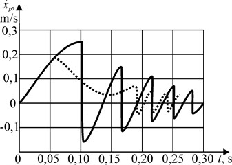
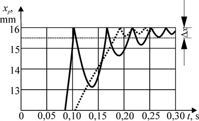
Fig. 2 shows the dependence of the speed of movement of 10 kg mass on time, obtained as a result of solving a system of equations in the developed software. The following parameters are set: piston diameter D=0,02 m, Dtr = 0,01 m, line pressurepM = 4∙105 Pa, x01= 0,016 m, f1 = 0,002 m, system drag coefficient during acceleration εc = 40, during braking εc= 800. Fig. 3 shows the vibration of the piston after impact. Solid curves correspond to the mode of operation of the drive without braking, dotted ones-with braking by throttling the input when the pistons are extended and the output when they are retracted.
Fig. 210 kg mass movement speed

Fig. 3Piston vibrations during the 10 kg mass movement

As can be seen from the graphs shown in Fig. 3, the working time of the piston of the specified position of 0,016 m without braking is 0,103 s, with braking it is 0,195 s. However, in the first case, the time when the vibration attenuation to a value not exceeding the positioning error of 0,5 mm was 0,246 s, and in the second case it was 0. Thus, the value of the impact velocity of the piston at the end of its stroke significantly affects the time of working out the specified coordinate by the piston.
Calculations have shown that the main operating time of the drive is occupied by the movement of pistons with a long stroke length. This makes it possible to reduce the speed of movement of the pistons with a small stroke without increasing the operating time of the drive. So, with the area ratio SN/SN+1= 0,25 and movement of the 2 kg mass for the stroke length of 1, 2, 4 and 8 mm, the movement time was 0,04, 0.073, 0,15 and 0,3 s, respectively, while the speed of the piston at the end of the stroke did not exceed 0,04 m/s. To move the same mass to the length of the stroke of the piston 64 and 128 mm, a braking scheme with throttling of the inlet was used. The braking distance was set constant, equal to 3/4 of the stroke of the piston, the coefficients εiwere calculated, providing the necessary braking intensity and speed at the end of the stroke of the piston, which did not exceed 0,04 m/s. At a steady speed of 0,6 and 0,66 m/s, braking was provided atεc = 600 and εc= 400, respectively, and the travel time in this case was 0,22 and 1,2 seconds. Thus, the travel time of the pistons with a stroke of 1 and 2 mm can be neglected in comparison with the travel time of the piston with a stroke of 128 mm. The question of whether braking is necessary for pistons with a stroke length of 4 and 8 mm can be resolved depending on whether the overall speed of the drive is provided with an increase in the travel time of the pistons.
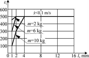
Fig. 4 shows the range of values of the drag coefficients εc, at which the speed of the piston at the end of the stroke does not exceed 0,1 m/s with the ratio of the areas of the pistons SN/SN+1= 0,75 for the moving masses 2,6 and 10 kg. The values of εc<500 correspond to the unsteady movement during acceleration of the piston, but the time of movement of the pistons is minimal. At εc>500, the steady-state speed of the pistons does not exceed 0,1 m/s for different moving masses and different piston strokes (1,..., 128 mm).
Fig. 4The range of values of the resistance coefficients εс

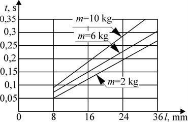
Fig. 5Dependence of the time of movement of the piston with braking at the end of the stroke on the stroke length

Fig. 5 shows the dependence of the time of movement of the piston with braking at the end of the stroke of the piston on the length of its stroke. As the calculations show, with an increase in the speed of movement and the implementation of the braking mode, the time of movement of the piston weighing 2 kg for a stroke length of 16 mm decreased from 0,21 to 0,12 s, which indicates the feasibility of using the braking mode in this case.
4. Conclusions
The practical value of the work is as follows.
Analytical dependences are obtained that allow us to refine the dynamic characteristics of the movement of a pneumatic multi-piston drive, taking into account the need for a smooth stop of the output rod. The method is software-implemented, the correctness of the results obtained is confirmed by test calculations.
The novelty of the work is as follows.
As a result of research, it was found that when determining the operating time of the drive, it is necessary to take into account not only the time of movement of the pistons, but also the time of attenuation of the amplitude of their oscillations after stopping.
Reducing the speed of movement of the pistons with small strokes practically does not affect the operating time of the drive.
The using of braking modes for pistons with a long stroke length provides lower piston stroke speeds, while the drive operation time does not significantly increase.
The use of braking at the end of the stroke of the pneumatic drive pistons allows you to improve its dynamic characteristics without significant hardware costs.
References
-
Gerasimov I., Belyaev D., Kazachkov A. There is an opinion. Electric drive and robotics. Control Engineering Russia, Vol. 4, Issue 46, 2013, p. 18-19, (in Russian).
-
Sarvarov A., Vasiliev A., Danilenko K., Menshchikova E. Comparative analysis of mechatronic system drives. Electrotechnical Systems and Complexes, Vol. 4, Issue 25, 2014, p. 21-25, (in Russian).
-
Rachkov M. Optimal control of the position of a pneumatic manipulator with the use of an observation loop. Journal of Computer and Systems Sciences International, Vol. 40, Issue 3, 2001, p. 504-509.
-
Yu X. Study on servo control strategy for pneumatic manipulator. International Conference on Measuring Technology and Mechatronics Automation, 2010, p. 641-644.
-
Shang C., Tao Meng G. D. Adaptive robust trajectory tracking control of a parallel manipulator driven by pneumatic cylinders. Advances in Mechanical Engineering, Vol. 8, Issue 4, 2016, p. 1-15.
-
Yin Y., Wang J. A nonlinear feedback tracking control for pneumatic cylinders and experiment study. American Control Conference Hyatt Regency Riverfront, St. Louis, MO, USA, 2009, p. 3476-3481.
-
Wang J., Wang D. Modelling study, analysis and robust servo control of pneumatic cylinder actuator systems. IEE Proceedings. Control Theory and Applications, Vol. 148, Issue 1, 2001, p. 35-42.
-
Meng D., Tao G., Zhu X. Adaptive robust motion trajectory tracking control of pneumatic cylinders. Journal of Central South University, Vol. 20, 2013, p. 3445-3460.
-
Munasypov R., Tselishchev O. Electropneumatic tracking drive in the adaptive springing system of a mobile robotic complex. Bulletin of the Ufa State Aviation Technical University, Vol. 3, Issue 56, 2016, p. 194-200, (in Russian).
-
Gribkov A., Shilin D., Filin I. Test of kinematic model by pneumatic manipulator. Bulletin of the Samara State Aerospace University, Vol. 3, Issue 34, 2012, p. 203-208, (in Russian).
-
Hertz E. V., Kreinin G. V. Calculation of Pneumatic Actuators. Reference Manual. Mashinostroenie, Moscow, 1975, p. 272, (in Russian).
-
Belyaev N., Uvarov Stepanchuk E. E. Pneumohydraulic Systems. Calculation and Design. Higher School, Moscow, 1988, p. 271, (in Russian).
-
Panovko Ya Introduction to the Theory of Mechanical Shock. Nauka, Moscow, 1977, p. 224, (in Russian).

