Abstract
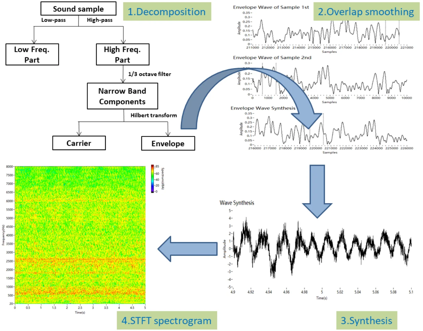
The synthesised sound of a car engine is used to alert people to the approach of an electric vehicle, to personalise the sound of an engine and for virtual reality. A methodology for synthesising engine sound based on concatenating samples is proposed. First, using filtering, the engine sound is decomposed into a combination of low-frequency harmonics that depend on the engine speed and high-frequency narrowband amplitude-modulated signals. The high-frequency signals are modulated by the harmonics that depend on the engine speed. The carrier and envelope of the amplitude-modulated signal are extracted with a Hilbert transform. The decomposed segments are concatenated by overlap smoothing. All the concatenated segments are assembled to form a synthesised sound. Finally, the synthesised sound is evaluated using the cepstrum distance and subjective auditory experiment, and it is compared with the raw engine sound and other synthesised sound.
Highlights
- The engine sound is decomposed into the low-frequency part composed of the fundamental frequency and its orders, the carriers and envelopes of the high-frequency narrowband components.
- The decomposed segments are concatenated by overlap smoothing, respectively.
- The synthesised sound is evaluated using the cepstrum distance and mean opinion score.
- This approach can synthesise engine sound samples of any length.
1. Introduction
Generated car engine sounds are useful in many situations. Electric vehicles are so quiet that an additional warning sound may be necessary [1], and the sound of an internal combustion engine has been suggested [2-4]. Some high-performance cars require a customised engine sound to meet the customers’ needs [5, 6]. Synthetic engine sounds are used in the virtual car driving simulators and virtual reality systems, which are used in driver training [7].
Existing approaches for generating an engine sound include spectral modelling and sampling [8]. Spectral modelling considers sound as a composition of a deterministic signal and a stochastic signal [9-14]. In this method, the sound model is simplified to reduce computational complexity. Engine sounds are regarded as a combination of low-frequency harmonics that depend on the engine speed and high-frequency stochastic noise. This method can effectively simulate the low-frequency part of the engine sound to produce a target sound. Spectral modelling can be used to personalise the sound, improve detectability and decrease the annoyance of a warning sound [2, 9]. A disadvantage of this methodology is that it requires detailed and complex calculations to reduce the monotony [8].
The other main method of synthesising engine sound is based on sampling [3, 15-18], which is called speech synthesis. It records real engine sounds as samples and chooses segments for the synthesis. This method can replicate most features of the sound. Concatenating different sound segments is key to the synthesis. A typical method for engine sound synthesis based on sampling is PSOLA (Pitch Synchronous Overlap and Add) [15]. PSOLA assumes that a sound is composed of independent segments, the widths of which are determined by a fundamental frequency. The gaps between sound samples must be considered. This method can synthesise low-frequency components well. However, it neglects the high-frequency components, and audible artifacts may be induced when looping the same sound sample.
In this study, synthesising engine sound based on sampling is discussed since the use of sampled engine sounds is widespread in practice [3, 8]. The auditory characteristics of synthesised engine sound can be improved by minimising the discontinuities at the concatenation points. High frequencies are concatenated in smoothing because of their contribution to the auditory characteristics. In this paper, the high-frequency part of engine sound is considered to be composed of different carriers and envelopes, and it is separated by 1/3 octave filtering and a Hilbert transform. Overlap smoothing is used to decrease the discontinuities due to the concatenation. Subjective and objective evaluations show that the synthesised signal is closer to the raw engine sound.
The structure of the paper is as follows. Section 2 succinctly introduces engine sound, and a model of engine sound is built. In Section 3, the decomposition and synthesis algorithm of engine sound are discussed. In Section 4, the process of decomposition and synthesis is detailed. In Section 5, the validity of the proposed approach is verified through subjective and objective evaluations. Finally, our conclusions are summarised in Section 6.
2. Acoustic characteristics of engine sound
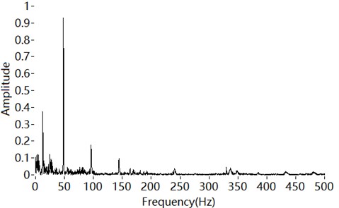
Engine sound comes from various sources, including the movement of pistons and valves, combustion in cylinders, the friction of belts and bearings, the intake and the exhaust. The various sources have different frequency distributions, all of which are related to the rotational speed of the engine. The fundamental frequency of engine sound, which is caused by in-cylinder pressure changes, also depends on the rotational speed. Therefore the low-frequency part of engine sound is dominated by the fundamental frequency, with lower amplitudes at the first and second orders. The higher orders are masked by noise, as shown in Fig. 1.
Fig. 1Low-frequency part of engine sound
The fundamental frequency for a four-stroke internal combustion engine is given by:
where N is the number of cylinders and n is the rotational speed.
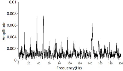
The high-frequency part of the engine sound is amplitude modulated by the fundamental frequency and its orders [19, 20]. Amplitude modulation plays an important role in sound recognition [21, 22]. Using only amplitude modulation, the sound recognition score can be over 85 % in a quiet environment [23, 24]. Yasui noted that the amplitude envelope affects the detectability of a vehicle’s warning sound [25]. Therefore, the amplitude modulation of engine sound should be considered in detail at high frequencies. The envelope spectrum of a narrowband component at high frequencies is extracted, as shown in Fig. 2. The peaks of the envelope spectrum are the fundamental frequency and its orders.
According to the above analysis, the low-frequency part of engine sound is a deterministic signal composed of engine orders, whereas the high-frequency part is composed of amplitude-modulated signals. The modulated frequencies are also engine orders. Zeller suggested that orders up to 18 are relevant [26]. However, the orders more than the third are masked by other noise, as shown in Figs. 1 and 2. Therefore, engine sound can be modelled as:
where n represents the engine orders,n=14,12,1,2,3. ω0 is the fundamental frequency, and An and φn are the amplitudes and initial phases of the harmonics, respectively. cos(ωit+φi) is the narrowband high-frequency signal, where ωi is the centre frequency of the narrowband signal. Bi is the amplitude of the modulated signal, and Mi is the modulation factor. ∑31/4sin(kω0t+φk) is the modulating signal, and k is the engine order,k=14,12,1,2,3.
Fig. 2Envelope spectrum of a narrowband high-frequency signal
3. Decomposition and synthesis
3.1. Decomposition
The low-frequency part is composed of the fundamental frequency and its harmonics. It is obtained by a low-pass filter.
The high-pass components are amplitude modulated. For a high-frequency component f(t), the Hilbert transform is defined as:
The Hilbert transform of f(t) can be regarded as a signal passing through a full-pass filter with amplitude 1. Through the transform, the positive frequency component is phase-shifted to –90° and the negative frequency component is phase-shifted to +90°. Therefore, the Hilbert transform is suitable for extracting the envelope only of a narrowband signal.
An amplitude-modulated signal can be described as:
where a(t) is the amplitude varied with time, and cos(ωt+φ) is a cosine signal.
To satisfy the narrowband condition, a(t) should be a slowly varying signal compared to cos(ωt). Here, ω is the carrier frequency.
For the engine sound model, a narrowband filtered component of the high-frequency part is:
The envelope and carrier can be obtained by a Hilbert transform as follows. The envelope is:
The carrier is:
where y(t)≥1 and the amplitude of the carrier is 1.
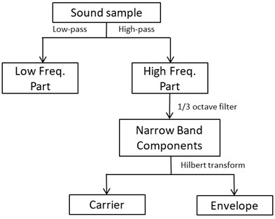
Finally, the decomposition process is summarised in Fig. 3. The engine sound is decomposed into three groups: the low-frequency part composed of the fundamental frequency and its orders, and the carriers and envelopes of the high-frequency narrowband components. A 1/3 octave filter can be used to obtain the high-frequency narrowband components from the high-frequency part. These components are synthesised by the overlap smoothing algorithm, which is described later.
Fig. 3Decomposition of engine sound
3.2. Overlap smoothing algorithm
The steps of PSOLA can be described as follows:
(1) The signal is decomposed into separate segments by windowing at particular time instances. These instances are positioned pitch synchronously and are called “pitch markers”.
(2) Optional modification of these segments, including pitch and speech rate.
(3) Recombination of the segments by means of overlap-adding.
The proposed synthesis method uses engine sound samples of different engine speed. The pitch and playback rate would not be modified. The overlap smoothing algorithm consists only of steps (1) and (3).
When two segments are concatenated, the end frame of the first segment and the start frame of the next segment are overlapped. The discontinuity between the frames has to be eliminated [27-29]. An example is given in Fig. 4.
The first step of the overlap algorithm is to add pitch synchronisation windows (Hann windows with a length of over one pitch period) for segments 1 and 2, respectively.
Fig. 4Overlap of engine sound segments
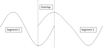
The length of the overlap of the segments has to be determined, as it affects the phase displacement and amplitude displacement of the segments.
As the overlap length becomes longer, the phase difference between the two segments becomes larger. The phase difference can be described as:
As the overlap length becomes shorter, the amplitude difference between the two segments becomes larger. The amplitude difference can be described as:
An overlap length of 50-75 % of the pitch length is appropriate [27].
The second step is processing the overlap. Let the weight of segment be, which decreases linearly with time. Let the weight of the next segment be, which increases linearly with time. The overlap frame can be described as:
where .
The overlap frame is a combination of the segment with a linear decrease over time and the next segment with a linear increase over time, which reflecting the smoothing transition of the engine speed.
According to the characteristic of the Fourier transform:
There is a weighted concatenation in the frequency domain corresponding to the overlap in the time domain. So, the spectrum of the overlaped frame is a weighted combination of the two segments, which ensures that the frequency transition is natural and eliminates the spectral mismatch.
The overlap smoothing algorithm can be described as follows:
1) Determine the pitch and add pitch synchronisation windows for segments.
2) Determine the length of the overlap.
3) Recombine the segments by weighted concatenation.
4. Synthesis of engine sound
4.1. Recording engine sounds
Sound samples were collected from a four-cylinder gasoline engine. A microphone was placed in the engine cabin to record the sounds, and the rotational speed was obtained from the on-board diagnostics. The engine sounds were recorded at intervals of 50 RPM from idle to 2400 RPM. The recording length was 15 s.
The sound samples are divided according to Fig. 3. The cut-off frequency of the 1/3 octave filter was 282 Hz, which divides the high and low frequencies. When the engine speed is 2400 RPM, the fundamental frequency is 80 Hz, and its third harmonic frequency is 240 Hz. The high-frequency part was further filtered by the 1/3 octave filter to obtain the narrowband components. Then, the Hilbert transform was adopted to obtain the carriers and envelopes .
4.2. Synthesis of the low-frequency part
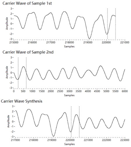
The low-frequency part is dominated by the fundamental frequency. It includes the first and second harmonics and a little clutter. We synthesise the sound segments with the overlap smoothing algorithm. When the next sound segment is to be played, we estimate the phase at the end of the current segment . The initial phase of the next segment is determined through pitch synchronisation. The two segments are then overlapped smoothly and added together. The length of the overlap is 50 % of the fundamental wavelength. A concatenation of two segments is shown in Fig. 5.
Fig. 5Concatenation of low-frequency segments
4.3. Synthesis of the carrier at high frequencies
The carrier of a high-frequency narrowband component obtained by the Hilbert transform is . We synthesise the sound segments of the carriers with the overlap smoothing algorithm. The amplitude of a carrier is 1. Therefore, the phase of the two segments can be aligned succinctly. The phase at the end of the current segment is estimated and taken as the initial phase of the next segment . The overlap length is estimated to be 50 % of the wavelength at the centre frequency of the 1/3 octave. The length should be longer if the centre frequency exceeds 2 kHz, because there are fewer sampling points at high frequencies. Then the two segments are concatenated by the overlap smoothing algorithm, as shown in Fig. 6.
Fig. 6Concatenation of carrier segments
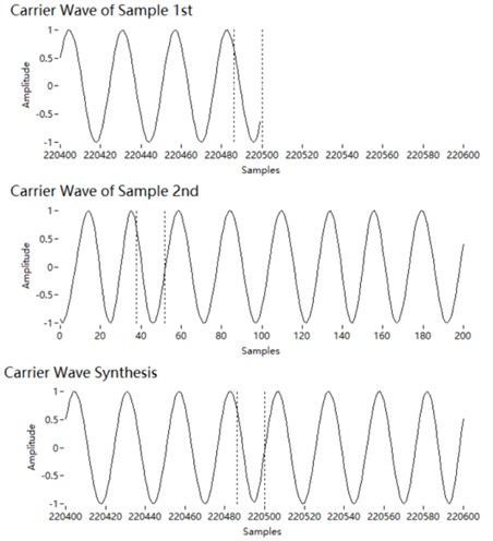
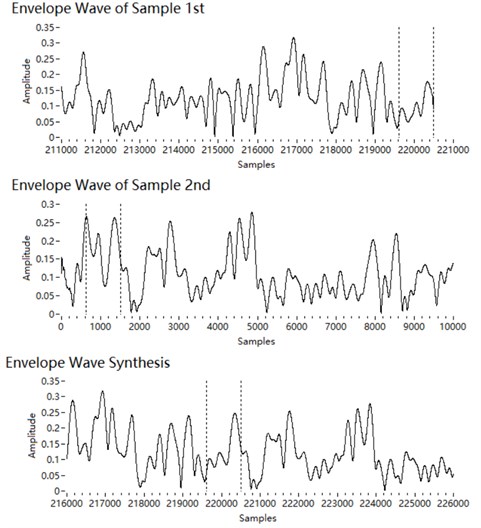
Fig. 7Concatenation of envelope segments
4.4. Synthesis of the envelope at high frequencies
The envelope of a high-frequency narrowband component obtained by the Hilbert transform is , which is positive. The amplitude modulation uses the orders of the fundamental frequency. We synthesise the sound segments of the envelopes with the overlap smoothing algorithm. The length of the overlap is larger to ensure a good match. Here, the overlap length is 150 % of the wavelength of the fundamental frequency. Since the envelope spectrum is still dominated by the fundamental frequency, peak points are set as pitch mark for phase alignment. There are at least two peak points in a fundamental period. Thus, the process is to search backwards for a peak point within 1.5 fundamental periods starting from the end of segment 1, and then search forwards for a peak point within 1.5 fundamental periods from the start of segment 2. Then the two segments are phase-aligned and smoothly overlapped with the peak points as pitch marks, as shown in Fig. 7.
4.5. Combining components
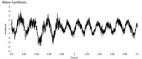
The three groups of components (the low-frequency part, the high-frequency carrier and the high-frequency envelope) are added to form the synthesised sound. As shown in Fig. 8, there is no apparent mismatch in the time domain.
Fig. 8Synthesised sound in the time domain
5. Validation
5.1. Dataset
A four-cylinder gasoline engine was considered. Its speed was 1500 RPM, and the fundamental frequency was 50 Hz. The sampling frequency was 44 kHz. There were 4000 points in one segment, and the duration of a segment was about 90 ms. The two methods compared are direct synthesis, which directly connects the end of one segment to the start of the next segment, and PSOLA. To evaluate the differences, the synthesis algorithms were run 100 times in sequence, which results in a set of synthetic sounds lasting about 9 s.
Fig. 9STFT spectrogram of non-synthetic engine sound
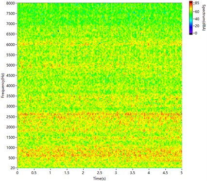
Fig. 10STFT spectrogram of directly synthesised sound
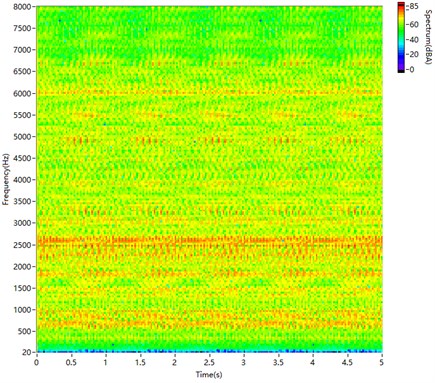
Fig. 11STFT spectrogram of sound synthesised by PSOLA
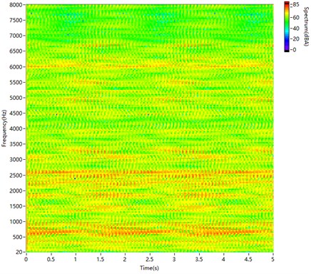
Fig. 12STFT spectrogram of sound synthesised by the proposed method
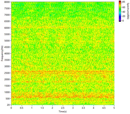
Fig. 9 is the A-weighting spectrogram for a short-time Fourier transform (STFT) of non-synthetic sound recorded from the engine. In the spectrogram, the main frequency bands are 500-1000 Hz and 2000-3000 Hz. The distribution is discrete in both the frequency and time domains.
Fig. 10 is the spectrogram of the directly synthesised sound. The sound segments are directly spliced together. In the spectrogram, there are few harmonics at low frequencies and many fish scales at high frequencies because of the phase mismatch.
As shown in Fig. 11, PSOLA can synthesise the low-frequency part well. However, it does not achieve a good match at high frequencies. There are fish scales in the spectrogram, and it is much different from Fig. 9.
The spectrogram in Fig. 12, produced by the proposed method, is very similar to Fig. 9, and it has nearly no fish scales.
5.2. Objective evaluation
The cepstrum distance is widely used to evaluate the quality of speech synthesis [30-32]. We calculate the cepstrum distance of amplitude modulation between the synthetic and non-synthetic engine sounds. The computation is performed through the following steps:
(1) Weight is added to account for the sensitivity of human hearing.
(2) 1/3 octave filtering is performed.
(3) The amplitude envelope of the filtered signal is extracted.
(4) The cepstrum of the amplitude envelope is computed (Hann windows, 512 points per frame).
(5) The distance between the synthetic and non-synthetic sound is calculated as:
where is the sequence number of the point, is the cepstrum of the filtered synthetic sound and is the cepstrum of the filtered non-synthetic sound.
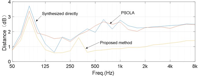
Fig. 13 shows the distance as a function of frequency for the synthetic sounds compared with non-synthetic sound. A lower distance means a less difference. These results confirm the visual observations in the high-frequency range. The distance for the proposed method is significantly shorter than those for the other methods at frequencies over 500 Hz.
Fig. 13Cepstrum distances for the three synthesised sounds
5.3. Subjective evaluation
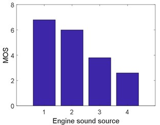
Subjective assessment is necessary for the quality evaluation of the synthesised engine sound as well as the synthesised speech. [11, 12, 33]. Naturalness is the difference between synthetic and natural sounds, and its popular index is mean opinion score (MOS) [34]. The final comparison was a subjective assessment of the sounds. Altogether, 21 people with normal hearing were recruited to evaluate the engine sounds. A listener is presented the pairs of car noise stimuli using loudspeakers in a soundproof room in which the sound level was lower than 38dBA. The engine sounds were played in a loop for 20 s by a loudspeaker. The listeners used a scale from 1 (extremely unnatural) to 7 (extremely natural). The mean opinion scores are computed from the assessment given by listeners. The results of this auditory experiment are summarised in Fig. 14. The non-synthetic sound is the most natural, and the directly synthesised sound is the least natural. The naturalness of the engine sound synthesised by the proposed method is significantly higher than for the sounds synthesised by the other two methods. The results of this subjective evaluation are consistent with the objective evaluation.
Fig. 14Results of an auditory experiment to evaluate the naturalness of the synthesised sounds. Issue 1 is the non-synthetic sound. Issue 2 is the sound synthesised by the proposed method. Issue 3 is the sound synthesised by PSOLA. Issue 4 is the directly synthesised sound
6. Conclusions
This paper presents an approach for engine sound decomposition and synthesis. The characteristics of engine sound are extracted by analysing the frequencies and amplitude modulation. The low-frequency part is represented by harmonics that depend on the engine speed. The high-frequency part is represented by narrowband carriers and envelopes, which are also harmonics that depend on the engine speed. The high-frequency part of the engine sound is not treated as stochastic noise, which is the key to improving the auralisation. The low-frequency part is obtained by a low-pass filter. The high-frequency part is filtered at 1/3 octave. A Hilbert transform is used to separate the carrier and envelope of the filtered high-frequency signals. The signals are concatenated by the overlap smoothing algorithm, which can reduce the phase and amplitude mismatch. The engine sound is then generated by combining the concatenated signals of the different frequency bands. This approach can synthesise engine sound samples of any length.
Subjective and objective evaluations of the method proposed were performed by comparing a raw engine sound with synthesised sounds. The spectrogram of the sound produced by the proposed method is very similar to the natural sound. There is a shorter cepstrum distance and a higher mean opinion score for the proposed method. They showed that the sound synthesised by the proposed method is closer to the raw engine sound.
References
-
U. Sangberg, “Adding noise to quiet electric and hybrid vehicels: An electric issue,” Noise News International, Vol. 20, No. 2, pp. 51–67, Jun. 2012, https://doi.org/10.3397/1.37022107
-
S. K. Lee, S. M. Lee, T. Shin, and M. Han, “Objective evaluation of the sound quality of the warning sound of electric vehicles with a consideration of the masking effect: Annoyance and detectability,” International Journal of Automotive Technology, Vol. 18, No. 4, pp. 699–705, Aug. 2017, https://doi.org/10.1007/s12239-017-0069-6
-
D. Min, B. Park, and J. Park, “Artificial engine sound synthesis method for modification of the acoustic characteristics of electric vehicles,” Shock and Vibration, Vol. 2018, pp. 1–8, 2018, https://doi.org/10.1155/2018/5209207
-
H. Konet, M. Sato, T. Schiller, A. Christensen, T. Tabata, and T. Kanuma, “Development of approaching vehicle sound for pedestrians (VSP) for quiet electric vehicles,” SAE International Journal of Engines, Vol. 4, No. 1, pp. 1217–1224, Apr. 2011, https://doi.org/10.4271/2011-01-0928
-
S. Kim, K.-J. Chang, D. C. Park, S. M. Lee, and S. K. Lee, “A systematic approach to engine sound design for enhancing sound character by active sound design,” SAE International Journal of Passenger Cars – Mechanical Systems, Vol. 10, No. 3, pp. 691–702, Jun. 2017, https://doi.org/10.4271/2017-01-1756
-
D. C. Park, E. S. Jo, S. Hong, and M. Csakan, “Development of personalized engine sound system using active sound design technology,” SAE International Journal of Passenger Cars – Mechanical Systems, Vol. 8, No. 3, pp. 862–867, Jun. 2015, https://doi.org/10.4271/2015-01-2216
-
S. Baldan, H. Lachambre, S. D. Monache, and P. Boussard, “Physically informed car engine sound synthesis for virtual and augmented environments,” in 2015 IEEE 2nd VR Workshop on Sonic Interactions for Virtual Environments (SIVE), pp. 1–6, Mar. 2015, https://doi.org/10.1109/sive.2015.7361287
-
A. Fortino, L. Eckstein, J. Viehöfer, and J. Pampel, “Acoustic vehicle alerting systems (AVAS) – regulations, realization and sound design challenges,” SAE International Journal of Passenger Cars – Mechanical Systems, Vol. 9, No. 3, pp. 995–1003, Jun. 2016, https://doi.org/10.4271/2016-01-1784
-
M. Sarrazin, K. Janssens, and H. van der Auweraer, “Virtual car sound synthesis technique for brand sound design of hybrid and electric vehicles,” in SAE Brasil International Noise and Vibration Colloquium 2012, Nov. 2012, https://doi.org/10.4271/2012-36-0614
-
Y. Stylianou, “Applying the harmonic plus noise model in concatenative speech synthesis,” IEEE Transactions on Speech and Audio Processing, Vol. 9, No. 1, pp. 21–29, 2001, https://doi.org/10.1109/89.890068
-
D. Berckmans, K. Janssens, H. van der Auweraer, P. Sas, and W. Desmet, “Model-based synthesis of aircraft noise to quantify human perception of sound quality and annoyance,” Journal of Sound and Vibration, Vol. 311, No. 3-5, pp. 1175–1195, Apr. 2008, https://doi.org/10.1016/j.jsv.2007.10.018
-
Y. Ban, H. Banno, K. Takeda, and F. Itakura, “Synthesis of car noise based on a composition of engine noise and friction noise,” in Proceedings of ICASSP '02, pp. 2105–2108, May 2002, https://doi.org/10.1109/icassp.2002.5745050
-
S. A. Amman and M. Das, “An efficient technique for modeling and synthesis of automotive engine sounds,” IEEE Transactions on Industrial Electronics, Vol. 48, No. 1, pp. 225–234, 2001, https://doi.org/10.1109/41.904583
-
R. Pieren, T. Bütler, and K. Heutschi, “Auralization of accelerating passenger cars using spectral modeling synthesis,” Applied Sciences, Vol. 6, No. 1, pp. 1–27, Dec. 2015, https://doi.org/10.3390/app6010005
-
J. Jagla, J. Maillard, and N. Martin, “Sample-based engine noise synthesis using a harmonic synchronous overlap-and-add method,” in ICASSP 2012 – 2012 IEEE International Conference on Acoustics, Speech and Signal Processing, Vol. 132, No. 5, pp. 3098–3109, Mar. 2012, https://doi.org/10.1109/icassp.2012.6287894
-
S. M. Costello and T. S. Stilson, “Crossfade sample playback engine with digital signal processing for vehicle engine sound simulator,” US patent 7 787 633, 2010.
-
T. J. van Rensburg, M. A. van Wyk, A. T. Potgieter, and W.-H. Steeb, “Phase vocoder technology for the simulation of engine sound,” International Journal of Modern Physics C, Vol. 17, No. 5, pp. 721–731, May 2006, https://doi.org/10.1142/s0129183106009333
-
D. Miljkovic, “Sample based synthesis of car engine noise,” in 2020 43rd International Convention on Information, Communication and Electronic Technology (MIPRO), pp. 1012–1017, Sep. 2020, https://doi.org/10.23919/mipro48935.2020.9245323
-
Q. Leclère, C. Pézerat, B. Laulagnet, and L. Polac, “Application of multi-channel spectral analysis to identify the source of a noise amplitude modulation in a diesel engine operating at idle,” Applied Acoustics, Vol. 66, No. 7, pp. 779–798, Jul. 2005, https://doi.org/10.1016/j.apacoust.2004.11.001
-
S. M. Lee, J. Back, K. An, and S. K. Lee, “Design and generation of a target sound to achieve the desired sound quality inside a car cabin,” International Journal of Automotive Technology, Vol. 21, No. 2, pp. 385–395, Apr. 2020, https://doi.org/10.1007/s12239-020-0036-5
-
Z. M. Smith, B. Delgutte, and A. J. Oxenham, “Chimaeric sounds reveal dichotomies in auditory perception,” Nature, Vol. 416, No. 6876, pp. 87–90, Mar. 2002, https://doi.org/10.1038/416087a
-
C. Lorenzi, G. Gilbert, H. Carn, S. Garnier, and B. C. J. Moore, “Speech perception problems of the hearing impaired reflect inability to use temporal fine structure,” Proceedings of the National Academy of Sciences, Vol. 103, No. 49, pp. 18866–18869, Dec. 2006, https://doi.org/10.1073/pnas.0607364103
-
R. V. Shannon, F.-G. Zeng, V. Kamath, J. Wygonski, and M. Ekelid, “Speech recognition with primarily temporal cues,” Science, Vol. 270, No. 5234, pp. 303–304, Oct. 1995, https://doi.org/10.1126/science.270.5234.303
-
R. V. Shannon, “Advances in auditory prostheses,” Current Opinion in Neurology, Vol. 25, No. 1, pp. 61–66, Feb. 2012, https://doi.org/10.1097/wco.0b013e32834ef878
-
N. Yasui, “Effect of amplitude envelope on detectability of warning sound for quiet vehicle,” in Inter-noise and Noise-con Congress and Conference, pp. 6479–6486, 2016.
-
P. Zeller, Handbuch Fahrzeugakustik-Grundlagen, (in German). 2nd ed, Germany: Vieweg Teubner Verlag, 2012.
-
J. A. Longster, “Concatenative speech synthesis: a Framework for Reducing Perceived Distortion when using the TD-PSOLA Algorithm,” Bournemouth University, 2003.
-
S. W. Zhu, “Optimal control of variational inequalities with delays in the highest order spatial derivatives,” Acta Mathematica Sinica, English Series, Vol. 22, No. 2, pp. 607–624, Apr. 2006, https://doi.org/10.1007/s10114-005-0688-0
-
F. M. Gimenez de Los Galanes, M. H. Savoji, and J. M. Pardo, “New algorithm for spectral smoothing and envelope modification for LP-PSOLA synthesis,” in ICASSP '94. IEEE International Conference on Acoustics, Speech and Signal Processing, pp. 573–576, 1994, https://doi.org/10.1109/icassp.1994.389229
-
Y. Stylianou and A. K. Syrdal, “Perceptual and objective detection of discontinuities in concatenative speech synthesis,” in 2001 IEEE International Conference on Acoustics, Speech, and Signal Processing. Proceedings, pp. 837–840, 2001, https://doi.org/10.1109/icassp.2001.941045
-
J. H. L. Hansen and D. T. Chappell, “An auditory-based distortion measure with application to concatenative speech synthesis,” IEEE Transactions on Speech and Audio Processing, Vol. 6, No. 5, pp. 489–495, 1998, https://doi.org/10.1109/89.709674
-
D. T. Chappell and J. H. L. Hansen, “A comparison of spectral smoothing methods for segment concatenation based speech synthesis,” Speech Communication, Vol. 36, No. 3-4, pp. 343–373, Mar. 2002, https://doi.org/10.1016/s0167-6393(01)00008-5
-
C.-F. Chi, R. S. Dewi, and M.-H. Huang, “Psychophysical evaluation of auditory signals in passenger vehicles,” Applied Ergonomics, Vol. 59, pp. 153–164, Mar. 2017, https://doi.org/10.1016/j.apergo.2016.08.019
-
T. Toda, H. Kawai, M. Tsuzaki, and K. Shikano, “An evaluation of cost functions sensitively capturing local degradation of naturalness for segment selection in concatenative speech synthesis,” Speech Communication, Vol. 48, No. 1, pp. 45–56, Jan. 2006, https://doi.org/10.1016/j.specom.2005.05.011
