Abstract
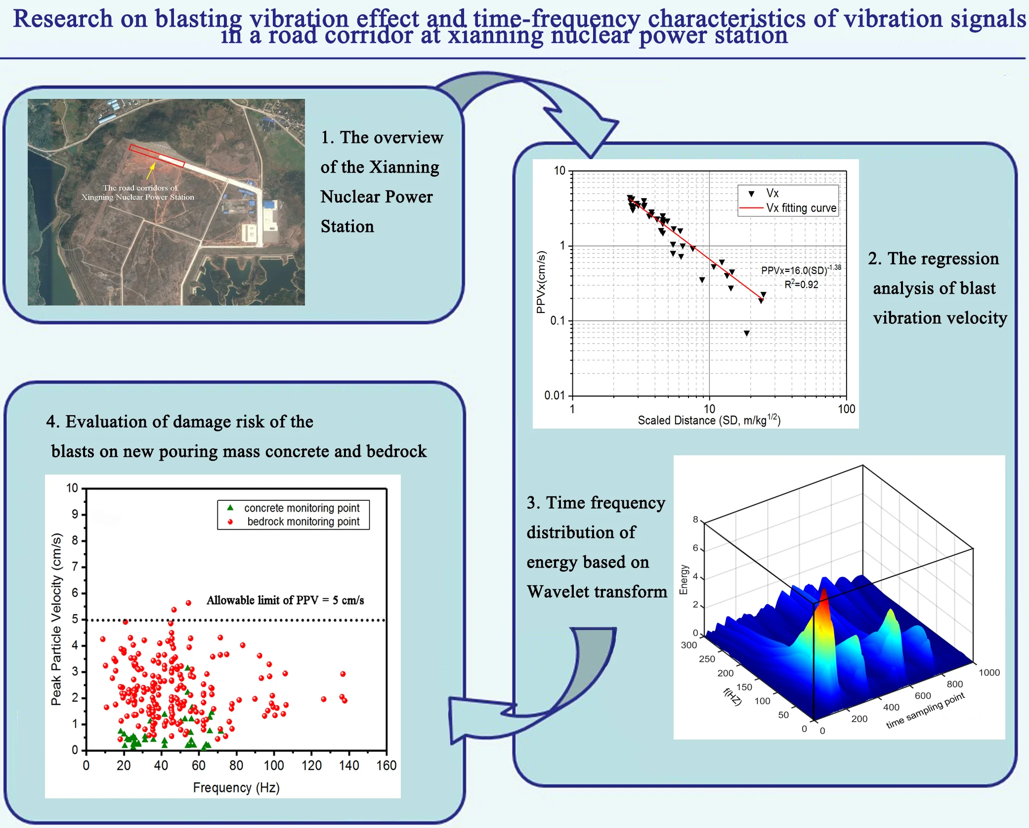
Drill and blast is a major method for foundation excavation in nuclear power plant engineering. For transporting heavy components to engineering construction, the blast-induced vibration of foundation excavation in a road corridor may has a great influence on new pouring mass concrete and surrounding bedrock in Xianning Nuclear Power Station, which will affect the safety of the engineering construction. So it is necessary to monitor the process of blasting excavation and put forward effective control measures on blasting vibration effect, in which the peak particle velocity (PPV) attenuation law are investigated through regression analysis of practical field data by Duvall empirical formula and the time-frequency characteristics was analyzed by wavelet transform and wavelet package decomposition. By analyzing the velocity amplitude and power spectrum density amplitude of wavelet components, it shows the blast energy of original vibration signal is mainly within the frequency below 250 Hz and has three sub-band which varies from 10 Hz to 30 Hz, from 40 Hz to70 Hz and from 75 Hz to 125 Hz, respectively. Wavelet packet analysis indicates the energy of the signal in 0-125 Hz accounts for 94.25 % of the total signal. At the same time, for the sake of ensuring the safety of road corridor, Chinese admissibility standards (GB6722-2014) of blasting-induced vibration and the constants obtained from the regression were used to establish the maximum explosive charge per delay for an acceptable ground vibration level that would not cause damage for new pouring mass concrete and bedrock in road corridor. The safety criteria of particle vibration velocity for new pouring mass concrete and bedrock in road corridor could be both set as 5 cm/s, which show the remarkable effect on blasting damage control of the new pouring mass concrete and surrounding bedrock, the results demonstrate that controlling maximum explosive charge per delay methodology can be commendably applied to road corridor to control blasting-induced vibration effects.
Highlights
- The peak particle velocity attenuation law is investigated through regression analysis of practical field data by Duvall empirical formula.
- The time-frequency characteristics are analyzed by wavelet transform and wavelet package decomposition.
- The safety criteria of particle vibration velocity for new pouring mass concrete and bedrock in road corridor is proposed.
- The maximum explosive charge per delay for an acceptable ground vibration level for new pouring mass concrete and bedrock in road corridor is established.
1. Introduction
China is in the stage of rapid economic development and continuous infrastructure construction, blasting engineering plays an increasingly prominent role in highway excavation, hydropower construction, underground space development and other fields [1, 2]; however, a series of negative effects caused by blasting have attracted widespread attention. The stress wave and explosion gases will not only reduce the joint strength and aggrandize the permeability of rock, but also cause building crack, landslide, tunnel collapse and many other hazards [3, 4]; therefore, it is necessary to control blasting vibration effect for ensuring the blasting damage of rock mass and building is within safety criterion range [5, 6]. In the construction of nuclear power project, in order to speed up the construction progress, the blasting excavation and the concrete pouring near the adjacent parts are often simultaneously executed, so there is a general problem that the impact of blasting vibration may damage the new pouring large volume concrete. The strength of concrete at different ages is different, for early age concrete with low strength, excessive blasting vibration will cause cracks in cement mortar or cracks at the junction of aggregate and slurry, even forming penetrating cracks, which will affect the later concrete strength [7]. According to the design requirements of Xianning nuclear power station, it is necessary to carry out foundation excavation blasting of road corridor for transporting heavy components to engineering construction, the stress wave and high pressure gas in the process of blasting excavation may cause different degrees damage to the new pouring mass concrete and surrounding rock mass, which will affect the safety of engineering construction, so it is necessary to monitor the process of blasting excavation and put forward effective control measures on blasting vibration effect for the safety of near new pouring large volume concrete and surrounding rock mass in blasting field.
Numerous researches on the blasting vibration effect of different engineering backgrounds such as highway tunnel, urban subway tunnel, nuclear power station, hydropower station and coal mining have been carried out using field measurement and theoretical analysis. Sun et al. [8] and Deng et al. [9] evaluated the safety distance and the causes of house cracking for buildings near the blasting area at highway, in addition, based on the excavation of Jiahua tunnel, the damage status of ground buildings in the blast vibration area was qualitatively analyzed by using the method of fault tree analysis in safety system engineering [10]. Li et al. [11] and Zeng et al. [12] studied the characteristics of wave propagation and blast-induced damage to rock mass by site seismic survey and sonic wave test; the relationship between peak particle velocity at 30 m away from the charge hole and the damage depth of rock mass is established, a simple method based on safety threshold of vibration velocity for rock mass to restrict the damage depth of rock mass under blasting excavation is presented. In order to assess damage controlling of blast vibrations considering rock properties of underwater blasting, Li et al. [13] proposed a novel model for predicting peak particle velocity (PPV) considering the effects of geological factor, rock properties and engineering category on the attenuation of ground vibrations and frequency, the novel predictor, formed by adding the depth ratio of the water to the scaled distance law suggested by Duvall and Fogelson, is verified by the agreement of measurement data with a correlation coefficient of 92 %. Nateghi [14, 15] described blasting-induced ground vibration level of underground and surface concrete structures and analyzed the effects of different rock formations, different detonators and explosives during the construction of upper Gotvand dam. Li [16] proposed a method to predict the time history of blast vibrations on high slopes, the spectral prediction and control of blast vibrations during the excavation of high dam abutment slopes with millisecond-delay blasting is presented in the Xiluodu hydropower project. Qiu [17] proposed a new blasting pattern using short-delay intervals in order to improve rock breaking and control blast induced vibrations in cutting blasting with single free surface in underground mines. Faramarzi [18] achieved simultaneous investigation of blast induced ground vibration and airblast effects on safety level of structures and human in surface blasting at Sungun Copper Mine, Iran. Ak [19, 20] examined the impacts of discontinuity frequency parameter on the propagation of blast-induced ground vibrations and analyzed the results of ground vibration measurement to predict peak particle velocity and to determine the slope attenuation curve on the blasting benches at a quarry mine in Turkey, the prediction graphics of maximum charge weight per delay versus distance for different damage criteria was proposed in order not to damage to nearby structures. Effect of bedding plane on prediction blast-induced ground vibration in open pit coal mines was researched, PPV attenuates more rapidly within the steeply dipping multiple bed rock masses down and up dip compared to along the strike [21]. Shin [22] attempts to identify the effect of blast-induced vibration on the adjacent tunnels in soft rock, a guideline for evaluating the blast protection zone is proposed based on a parametric study on blast location, tunnel depth, and the amount of explosives. Yu [23] evaluated influence of vibrations generated by blasting construction on an existing tunnel in soft soils by field monitoring and finite element software ABAQUS. Similarly, Xia [24] presented a case study on rock damage prediction and control method for underground tunnels subjected to adjacent excavation blasting, the effects of tunnel blast excavation on the surrounding rock mass and the lining systems of adjacent existing tunnels are comprehensively studied for the Damaoshan highway tunnel project. Gou [25] assessed attenuation of blast-induced vibrations derived from an underground mine, the influence of blasting design, propagating medium and its mechanical parameters on PPV and frequency attenuation law were also carefully investigated. Singh P. K. [26] and Roy [27] studied blast vibration effects in an underground mine caused by open-pit mining, ground vibration recorded at roof, pillar and floor were analyzed separately and the threshold value of vibration for the safety of underground workings has been determined based on the Rock Mass Rating values of the roof rock, at the same time, accordingly blast designs have been optimized. In order to assess the influence of underground mining blasting on the stability of open pit slopes and control the potential risk, Jiang and Zhou [28] investigated a mathematical model to describe the attenuation of blasting vibration on open pit slopes subjected to underground mining blasting in Daye Iron Mine, the PPV predicting model for high slopes at different elevations was proposed based on the numerical simulations of underground mining blasting.
As for the time-frequency characteristic and safety standards of blasting vibration signal, Li et al. [29] analyzed a practical blasting vibration signal by means of wavelet transform (WT) and Hilbert-Huang Transform (HHT), the presented results show that both WT and HHT are efficient ways for analyzing and processing non-stationary signals, and can draw main characteristic information from signals as well as carry out wave filtration and noise elimination. The influence of the blasting vibration on the structure was assessed based on the relation between characteristic frequency of blasting seismic signals on different frequency bands and natural frequency of controlled structure by means of the wavelet packet analysis, a practical engineering example proved that the wavelet packet analysis method was more effective than the safety-judging standard of single intensity factor for blasting vibration [30]. Zhong et al. [31] discussed the dynamic response of structures and the effect of inherent characteristics of controlled structures to blasting vibration, frequency band response coefficients and multi-factor blasting vibration safety criteria for controlled structures by blasting vibration have been obtained. Besides, energy distributions for different frequency bands of blast vibration signal are obtained and the characteristics of energy distributions for blast vibration signal measured under different explosion parameters (the maximum explosive weight per delay, the distance of blast source to measuring point and the section number of millisecond detonator) are analyzed [32]. Zhao [33] study the time–frequency characteristics of blasting vibration signals measured in milliseconds by applying a combination of reassigned smoothed pseudo Wigner-Ville distribution (RSPWVD) and wavelet at an open pit of the Jinduicheng Mine, the effect of milliseconds intervals on time-frequency characteristics of blasting vibration signals is significant. Han and Ma [34] studied the impacts of blasting vibration on surrounding rock and existing roadway structure by taking driving blasting in coal mine rock roadway as engineering background, in which wavelet packet method is used to decompose blasting vibration signals and to draw energy distribution features in different frequency bands. The accurate identification of delay time in millisecond blasting plays an important role in the optimization of blasting design and reduction of vibration effect, Shi et al. [35] compared the capability of the empirical mode decomposition (EMD) method with the instantaneous energy method based on Hilbert-Huang transform (HHT) in identifying the delay time of short millisecond blasting under precise initiation, it was found that the instantaneous energy method was adaptable to millisecond blasting with delay time longer than half of the energy peak period. In order to ensure the safety of mining, Li [36] studied the wave characteristics of natural mineral earthquake and blast in a coal mine based on the Hilbert-Huang transform (HHT) method; the dominant frequency of natural mineral earthquake wave is 20 Hz, however, the blast wave frequency is relatively complex and its dominant frequency is 140 Hz. Lu et al. [37, 38] introduced the safety standards of blast vibrations and the results of blast vibration measurements during bedrock excavations in Three Gorge Project and discussed several important problems related to the safety standards; the domestic safety criteria of blasting vibration and permitted standard of blasting velocity for high rock slope, underground caverns, foundation rock mass and early-aged concrete adopted in field of hydropower engineering are presented. Blasting excavation in a tunnel passing beneath an airport is quite rare at home and abroad, Lu et al. [39] carried out monitor vibration and investigated effect of excavation blasting by the dynamic finite element program LS-DYNA in an under-cross tunnel on airport runway; the numerical results showed that the airport runway was affected little and an existed cave could amplify the amplitude of blasting vibration to an extent, in addition, the safety threshold for the airport runway induced by blasting vibration was obtained.
For transporting heavy components to engineering construction, the blast-induced vibration of foundation excavation in a road corridor may has a great influence on new pouring mass concrete and surrounding bedrock in Xianning Nuclear Power Station, which will affect the safety of the engineering construction; the study on peak particle velocity (PPV) attenuation law and time-frequency characteristics of blasting vibration signal is of great importance to control vibrations induced by bench blasting. In order to reduce the damage extent to new pouring mass concrete and surrounding rock mass during the foundation blasting excavation of the road corridor, the peak particle velocity (PPV) attenuation law of blasting vibration signal has been studied through regression analysis of practical test data by Duvall empirical formula and the time-frequency characteristics of blasting vibration signal was analyzed by wavelet transform and wavelet packet transform. Furthermore, some feasible measures to mitigate the negative effects of blasting induced vibrations is given, Chinese admissibility standards (GB6722-2014) of blasting induced vibration and the constants obtained from the regression were used to establish the maximum explosive charge per delay for an acceptable ground vibration level that would not cause damage for new pouring mass concrete and bedrock in road corridor.
2. Theory
2.1. Characteristics of wave propagation
Base on wave theory and elasticity theory, when rock mass vibrates by reason of disturbance in the case of plane waves, the rock mass stress σ for blasting can be obtained as follow [40]:
where E is elastic modulus, ε is strain and ν, cp is particle vibration velocity, propagation speed of vibration wave, respectively.
Combine Eq. (2) with Eq. (1), it show that:
We can find that the rock mass stress for blasting is proportional to particle vibration velocity; the particle vibration velocity is an important physical quantity, which can reflect the blast-induced rock mass damage, the measurement of particle vibration velocity is more convenient than the direct measurement of rock mass damage.
In general, most predictor equations of the ground vibration velocity are developed based on: (1) the maximum explosive weight per delay, Q, and (2) the distance between the monitoring point and blasting point, R. Several common empirical relationships have been suggested to describe the attenuation of blast-induced ground vibration, such as Eqs. (4)-(8) obtained by Duvall and Fogelson [41], Langefors and Kihlstrom [42], IS 6922 [43], Pal Roy [44], and GB6722-2014 [45], respectively:
where PPV stands for the peak particle velocity at the target point, according to United States Bureau of Mines (USBM), the attenuation Eq. (4) is used most widely to study the attenuation of blast vibration [46-48], the Duvall Formula points out [41]: Q is the maximum explosive weight per delay (kg), R is the distance between the blasting source and the measurement point (m), SD=R/Q1/2 is the scaled distance (m/kg1/2), K is the blasting design and field geology coefficient, and a is the attenuation coefficient.
2.2. Wavelet transform and wavelet packet transform
Wavelet analysis is a kind of time and frequency analysis method which implement discrete transform of signal in time domain and spectrum analysis in frequency domain, it has a good localization in both time and frequency domain, which can solve the contradiction between time and frequency resolution. For the low frequency components of the signal, the wide time window can make the resolution in time domain is low and the resolution in frequency domain is high; For the high frequency components of the signal, the narrow time window can make the resolution in time domain is high and the resolution in frequency domain is low; It has many advantages and is widely used in the analysis of blasting vibration signal [40, 49].
R denotes the set of real numbers. L2(R) denotes the vectors space of measurable, square integrable one- dimensional functions ϕ(t).
Supposing ϕ(t)∈L2(R) and Fourier transform of ϕ(t) is ˆϕ(ω), if ˆϕ(ω) satisfy:
then ϕ(t) is called a basis wavelet function or mother wavelet function, a set of wavelet can be obtained through the shift and scale of ϕ(t).
For the continuous case, the wavelet sequence is:
where a is scale factor, b is shift factor.
For the discrete case, the wavelet sequence is:
where scale factor a is taken as a=2j, shift factor b is taken as b=2jk(j,k∈Z).
The continuous wavelet transform of any function f(t)∈L2(R) is:
where ⟨f,ϕa,b⟩ denotes the inner product between f(t) and ϕa,b(t); ¯ϕ((t-b)/a) is conjugate function of ϕ((t-b)/a).
The continuous wavelet inverse transform is:
The discrete wavelet transform (DWT) coefficient corresponding to function f(t) and its reconstruction formula are:
where C is a constant of not related to the signal.
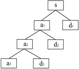
The frequency band of the signal obtained by the wavelet analysis is divided in equal interval. If the frequency range of the analyzed signal is (0, W), then it is divided into two parts of low frequency a1 (0, W/2) and high frequency d1 (W/2, W) after one layer decomposition. The second layer wavelet decomposition is further decompose the low-frequency part a1 (0, W/2) of the first layer decomposition to two parts of low frequency a2 (0, W/4) and high frequency d2 (W/4, W/2); in this way, the result of wavelet decomposition of N layer can be gained by decomposing N times (scale N). The 3-layer discrete wavelet decomposition tree on vibration signal is illustrated in Fig. 1.
Fig. 13-layer discrete wavelet decomposition tree on vibration signal
In view of the phenomenon of wavelet transform only can decompose the sub band of low frequency signal and no longer decompose the sub band of high frequency signal in the process of wavelet analysis which results in its frequency resolution decrease with the increase of frequency of signal, Wickerhauser and Coifman put forward the concept of wavelet packet decomposition and made the strict derivation mathematically [49]. The basic idea of wavelet packet transform is that the high frequency part which is not decomposed in wavelet transform is also decomposed into high frequency and low frequency parts, and the similar multi-layer partition is carried out in sequence, it can adaptively select the corresponding frequency band matching the signal frequency band according to the signal being analyzed.
The algorithm of wavelet package decomposition can be expressed as [50]:
where i is the number of decomposition layer, j∈{0,1,2,…,2i-1} denotes the index of nodes in the ith layer, di,j denotes the coefficient sequence of the jth node in the ith layer, d0,0is the received signal, and hl-2k and gl-2k are a low-pass filter and a high-pass filter, respectively, obtained from a pair of conjugate mirror filters. The wavelet packet decomposition tree up to decomposition layer 3 is demonstrated in Fig. 2.
Fig. 23-layer wavelet package decomposition tree on vibration signal

When the signal is analyzed in the wavelet packet analysis, the depth of the wavelet packet decomposition must be determined first. If the sampling frequency of the blasting vibration signal s(t) is 2f, the Nyquist frequency is f according to the Shannon sampling theorem; the wavelet packet decomposition is carried out at i decomposition layer, total j=2i sub band can be obtained and the frequency width of each sub-band is f/2i, the energy of each frequency band signal can be obtained by reconstructing the wavelet packet decomposition coefficient and extracting each band range signal from original signal. s(t) can be expressed as [34]:
where si,j denotes the reconstruction signal of the node (i,j) in the ith layer of wavelet packet and j=0,1,2,…,2i-1.
In the wavelet packet energy spectrum, the square sum of the signal in each sub frequency band can be selected as the symbol of the energy, the energy of the jth node in layer i can be defined as:
where xi,j is the discrete point amplitude of reconstructed signal si,j (j=0,1,2,…,2i-1; k= 1, 2,…, m, m is the number of discrete sampling points).
The total energy E0 of blasting vibration signal s(t) can be expressed as:
The ratio of the energy of each sub frequency band to the total energy of blasting vibration signal is expressed as:
2.3. Safety criterion of blasting vibration effect
The rock mass failure in the near area and middle area of the blasting source is mainly caused by explosion shock wave and stress wave, respectively. Usually, the stress wave theory is used to determine the safety criterion of bedrock fracture for blasting vibration. According to the variation form of Eq. (3), it show that:
where [PPV] is the allowable peak velocity of particle vibration, [εt] is the allowable tensile strain, and [σt] is the allowable tensile strength of rock.
It is deduced from Eq. (21) that there is a positive relationship between the peak particle velocity and the dynamic tensile strain or the dynamic tensile stress of the rock mass; therefore, according to the dynamic tensile strength [σt] or dynamic ultimate tensile strain [εt] of rock mass, the allowable threshold value of peak particle velocity [PPV] can be determined.
Due to the complexity of structural dynamic response characteristics, the safety criteria for blasting vibration of building, rock slope, surrounding rock mass of cavern and fresh concrete adopt single particle vibration velocity has great limitation, which cannot fully reflect the integrated influence of blasting frequency and duration of vibration on dynamic characteristics of corresponding structures and rock mass. Thus, the United States, Switzerland, Germany and China simultaneously taken vibration velocity and frequency into account when regulate the safety standards for blasting vibration, where different critical vibration velocities are used at different frequencies. However, there is no systematic research on the effect of duration on the safety criterion of blasting vibration at domestic and foreign.
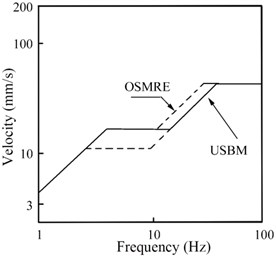
As shown in Fig. 3, Office of Surface Mining Reclamation and Enforcement (OSMRE) and the United States Bureau of Mines (USBM) in American put forward the relevant safety criterion of blasting vibration [51].
Fig. 3Safety criteria of USBM and OSMRE
In terms of ground building, central control room equipment at hydropower station and power plant in service, hydraulic tunnel, traffic tunnel, mine tunnel, high rock slope and the new pouring mass concrete, Chinese admissibility standards, i.e. “Safety regulations for blasting” (GB6722-2014) point out safety criteria in consideration of peak particle velocity and dominant frequency. Blasting vibration safety criteria established in China are listed in Table 1.
Table 1Blasting vibration criteria at China “Safety regulations for blasting” (GB6722-2014)
Sequence number | Protective structure | Permitted particle vibration velocity(cm/s) | ||
f≤ 10 Hz | 10 Hz <f≤ 50 Hz | f> 50 Hz | ||
1 | Cave dwelling, adobe building and freestone building | 0.15-0.45 | 0.45-0.9 | 0.9-1.5 |
2 | Common civil building | 1.5-2.0 | 2.0-2.5 | 2.5-3.0 |
3 | Industrial building and commercial building | 2.5-3.5 | 3.5-4.5 | 4.2-5.0 |
4 | General ancient architecture and historic site | 0.1-0.2 | 0.2-0.3 | 0.3-0.5 |
5 | Central control room equipment at hydropower station and power plant in service | 0.5-0.6 | 0.6-0.7 | 0.7-0.9 |
6 | Hydraulic tunnel | 7-8 | 8-10 | 10-15 |
7 | Traffic tunnel | 10-12 | 12-15 | 15-20 |
8 | Mine tunnel | 15-18 | 18-25 | 20-30 |
9 | Permanently high rock slope | 5-9 | 8-12 | 10-15 |
10 | The new pouring mass concrete(C20): Curing time: initial solidification- 3d Curing time: 3d-7d Curing time: 7d-28d | 1.5-2.0 3.0-4.0 7.0-8.0 | 2.0-2.5 4.0-5.0 8.0-10.0 | 2.5-3.0 5.0-7.0 10.0 – 12.0 |
For new pouring mass concrete (C20), the allowable limit of particle vibration velocity is different on the basis of dominant frequency and curing time, when the dominant frequency is f≤ 10 Hz, 10 Hz<f≤ 50 Hz and f> 50 Hz, respectively, for curing time between initial solidification and 3d, the allowable limit of particle vibration velocity is 1.5-2.0 cm/s, 2.0-2.5 cm/s and 2.5-3.0 cm/s, respectively; for curing time between 3d and 7d, the allowable limit of particle vibration velocity is 3.0-4.0 cm/s, 4.0-5.0 cm/s and 5.0-7.0 cm/s, respectively; for curing time between 7d and 28d, the allowable limit of particle vibration velocity is 7.0-8.0 cm/s, 8.0-10.0 cm/s and 10.0-12 cm/s, respectively.
Table 2PPV criterion for the blast induced damage [54]
Peak particle velocity (cm/s) | Effects of damage |
< 25.0 | No fracturing of intact rock |
25.0-63.5 | Millar tensile slabbing will occur |
63.5-254.0 | Strong tensile and some radial cracking |
254.0 | Complete break-up of rock mass |
Table 3PPV criterion for the blast induced damage [55]
Rock type | Uniaxial compressive strength (MPa) | RQD (%) | Peak particle velocity (cm/s) | ||
Minor damage | Medium damage | Heavy damage | |||
Soft schist | 14-30 | 20 | 13.0-15.5 | 15.5-35.5 | > 35.5 |
Hard schist | 49 | 50 | 23.0-35.0 | 35.0-60.0 | > 60.0 |
Shultze granite | 30-55 | 40 | 31.0-47.0 | 47.0-170.0 | > 170.0 |
Porphyry granite | 30-85 | 40 | 44.0-77.5 | 77.5-124.0 | > 124.0 |
A number of safety criteria for peak vibration velocity of rock mass cracking have been put forward at home and abroad by new crack investigation and acoustic test before and after bedrock blasting. For example, Langefors and Kihlstrom [42] take the peak particle velocity of 60 cm/s as the critical value of new rock cracks; Zhang [52] measured the micro-cracking zone boundaries of rock mass in blasting using the computer tomography (CT) and the allowed critical vibration velocities of rock particles are calculated which are 13.8-16.6 cm/s. Huang et al. [53] found that the remained bedrock was very slightly damaged when the PPV of rock mass is under 3.5 cm/s. Bauer A. [54] and Mojitabai N. [55] suggested the safety criterion for the peak vibration velocity for the blasting damage of the rock mass is shown in Table 2 and Table 3, respectively; it is shown that there is no fracturing damage of intact rock for blasting excavation when peak particle velocity is under 25.0 cm/s, minor damage will exist when the peak vibration velocity is greater than 13.0-15.5 cm/s, 23.0-35.0 cm/s, 31.0-47.0 cm/s and 44.0-77.5 cm/s for soft schist, hard schist, shultze granite and granite porphyry, respectively.
3. Case study
3.1. Introduction to Xianning Nuclear power station
The Xianning Nuclear Power Plant with a total installed capacity of 6000 MW (4 × 1000 MW) Advanced passive pressurized water reactor (AP1000) lies on Xianning city, the south of Hubei Province, China. Its geographical location is at longitude 114° 40'52'' E and latitude 29°40'38'' N, The project construction scale will be divided into two phases and two AP1000 nuclear power units are planned in the first phase.
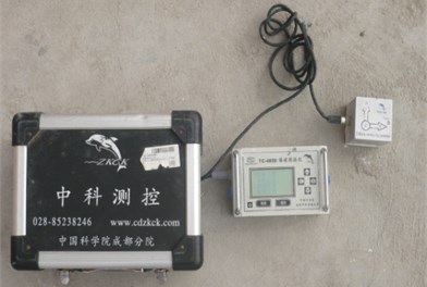
In construction site of the blasting for foundation excavation of the road corridor, the blasting seismic monitoring has been conducted in order to reduce the damage extent to the new pouring mass concrete and surrounding rock mass; the overview of the Xianning Nuclear Power Station, the layout of blasting vibration monitoring points and the blasting vibration monitoring system for foundation excavation blasting is shown in Fig. 4, Fig. 5, and Fig. 6, respectively.
Fig. 4The overview of the Xianning Nuclear Power Station
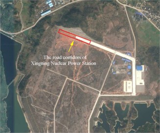
Fig. 5The layout of blasting vibration monitoring points
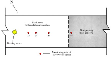
Fig. 6Blasting vibration monitoring system
3.2. Peak particle velocity attenuation law
During the experiments, 252 blasting vibration data along the horizontal radial, horizontal tangential and vertical direction were recorded from 84 blasting monitoring points of 19 shots. Summary of experimental blast design parameters at road corridor in Xianning nuclear power station is given in Table 4. Parts of vibration measurement results of peak particle velocity under explosion are shown in Table 5.
Table 4Summary of blast design parameters at road corridor in Xianning nuclear power station
No. of shots | Diameter of hole (mm) | Burden (m) | Spacing (m) | Depth of blast hole (m) | Length of stemming (m) | Total charge (kg) | Maximum charge per delay (kg) | Initiation systems | Explosives |
19 | 90 or 115 | 2.2-3.0 | 2.2-2.5 | 2.7-8.8 | 2.0-3.5 | 300-1107 | 40-184 | Non-electric shock tube delay detonator and milli-second connector | Emulsion explosive |
Table 5Parts of vibration measurement results of peak particle velocity under explosion
Sequence No. | Measuring point location | Maximum explosive weight per delay (kg) | Total explosive weight (kg) | Distance (m) | Horizontal radial direction | Horizontal tangential direction | Vertical direction | |||
PPVx (cm/s) | f (Hz) | PPVy (cm/s) | f (Hz) | PPVz (cm/s) | f (Hz) | |||||
1 | rock mass | 93 | 408 | 27 | 3.42 | 15.62 | 3.25 | 41.66 | 3.12 | 41.66 |
2 | rock mass | 93 | 408 | 44 | 1.51 | 55.55 | 1.84 | 62.50 | 1.96 | 29.41 |
3 | concrete | 93 | 408 | 138 | 0.28 | 27.77 | 0.23 | 25.00 | 0.23 | 27.77 |
4 | rock mass | 104 | 634 | 27 | 4.03 | 83.33 | 3.66 | 41.66 | 3.89 | 18.52 |
5 | rock mass | 104 | 634 | 30 | 3.74 | 20.00 | 3.13 | 29.41 | 3.38 | 38.46 |
6 | rock mass | 104 | 634 | 37 | 2.54 | 62.50 | 2.13 | 38.46 | 2.12 | 62.50 |
7 | concrete | 104 | 634 | 90 | 0.36 | 41.67 | 0.31 | 62.50 | 0.38 | 41.67 |
8 | rock mass | 80 | 400 | 30 | 3.57 | 47.50 | 3.11 | 48.46 | 3.35 | 38.50 |
9 | rock mass | 80 | 400 | 37 | 2.34 | 25.50 | 2.41 | 30.41 | 2.17 | 20.46 |
10 | rock mass | 80 | 400 | 49 | 1.73 | 51.67 | 1.83 | 50.50 | 1.32 | 21.67 |
11 | concrete | 80 | 400 | 110 | 0.62 | 20.12 | 1.12 | 34.12 | 0.73 | 18.25 |
12 | rock mass | 96 | 666 | 27 | 3.06 | 45.45 | 2.91 | 31.25 | 2.91 | 50.00 |
13 | rock mass | 96 | 666 | 37 | 2.66 | 41.66 | 2.82 | 38.46 | 2.75 | 50.78 |
14 | rock mass | 96 | 666 | 74 | 0.94 | 27.77 | 0.82 | 31.25 | 0.56 | 45.45 |
15 | concrete | 96 | 666 | 183 | 0.07 | 62.50 | 0.18 | 41.67 | 0.12 | 25.00 |
16 | rock mass | 80 | 400 | 24 | 3.50 | 46.45 | 3.11 | 56.25 | 2.40 | 52.00 |
17 | rock mass | 80 | 400 | 37 | 2.30 | 35.71 | 2.19 | 22.73 | 2.12 | 55.55 |
18 | rock mass | 80 | 400 | 44 | 2.19 | 62.50 | 2.05 | 45.45 | 1.55 | 45.45 |
19 | rock mass | 80 | 400 | 57 | 1.02 | 41.66 | 0.95 | 41.67 | 1.28 | 38.46 |
20 | concrete | 80 | 400 | 96 | 0.54 | 25.00 | 0.48 | 25.88 | 0.69 | 55.56 |
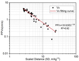
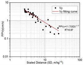
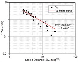
For foundation excavation blasting, total 117 blasting vibration data from 39 blasting monitoring points of first 10 shots from bench blasting are selected to fit in the form of power function based on Eq. (4); The regression analysis results of peak particle velocity, PPV, and the scaled distance, SD, along the horizontal radial, horizontal tangential and vertical direction are shown in Fig. 7.
The Duvall Formula on regressive analysis along the horizontal radial, horizontal tangential and vertical direction is expressed as Eq. (22), Eq. (23) and Eq. (24), respectively. The determination coefficients (R2) for Eq. (22), Eq. (23) and Eq. (24) is 0.92, 0.87 and 0.87, respectively, it indicates that the power law of attenuation Eq. (4) has a good fitting consistency:
The blast-induced peak particle velocity attenuation law is obtained in the form of Eq. (22), Eq. (23), and Eq. (24), based on the above equation, we can effectively present the blasting design about the maximum explosive weight per delay, Q, according to the allowable peak particle velocity, PPVlimit, at different distance from the center of explosion, R, in terms of requisition of “Safety regulations for blasting” (GB6722-2014) and expert opinion in China:
Fig. 7The regression analysis of blast vibration velocity
a) Horizontal radial direction
b) Horizontal tangential direction
c) Vertical direction
In term of Duvall empirical formula in Eq. (4), parameter K is directly proportional to particle vibration velocity and parameter a represent declining speed of particle vibration velocity where the bigger of a, the faster of velocity attenuation along propagation distance. It is observed in Eqs. (22-24) that the range of variation for K is from 10.0 to 16.0 and a is from 1.11 to 1.38 where it has been observed that K, a of horizontal radial direction is largest, this is, 16.0 and 1.38, respectively; but K, a of horizontal tangential direction is 11.7 and 1.17, respectively and K, a of vertical direction is 10.0 and 1.11, respectively. It is easy seen that the K of horizontal radial direction is more than horizontal tangential and vertical direction while a of horizontal radial direction is also more than horizontal tangential and vertical direction, it mean that horizontal radial direction has faster speed of velocity attenuation, As consistent with the results shown in Table 5, in spite of PPV of horizontal radial direction generally is larger than horizontal tangential and vertical direction in the near field of blasting source, however, the PPV of horizontal radial direction will be lower than horizontal tangential and vertical direction in the far field of blasting source. So it is noteworthy that we should take three different direction components of particle vibration velocity rather than single direction into account as safety criteria for blasting vibration.
3.3. Time-frequency characteristics for blasting vibration signal
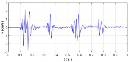
As shown in Fig. 8, there is a typical multiple section raw signal of millisecond blasting seismic wave with four sections of electric detonator monitored at 37 m away from the explosion source. The sampling points are 1000 and sampling interval time is 0.001 s. The original vibration signal (Fig. 8) will be decomposed and reconstructed by wavelet transform, the selection of wavelet basis function is the most direct problem in the application of wavelet analysis, since there is not absolutely same conclusion when different wavelet basis function is used to analyze the same signal, the selection of wavelet basis function has an important influence on the correctness of signal analysis; the commonly used wavelet basis function of non-stationary vibration signal analysis mainly come from db3, db5, sym5 and coif3; through the comparative analysis of signal reconstruction and relative error of blasting vibration signal, it is found that db3, db5, sym5 and coif3 wavelet basis function all have good reconstruction ability and extremely low relative error range within the order of 10-11 [29, 56, 57], where db5 is chosen as the wavelet basis function of wavelet transform for blasting vibration signal.
Fig. 8The velocity curve of original vibration signal
According to the characteristics of the instrument and sampling theorem, the sampling frequency of the signal is set to 1000 Hz, and the Nyquist frequency of the signal is 500 Hz. Therefore, according to the principle of wavelet analysis (Fig. 1), the original vibration signal is decomposed into 7 levels and total 8 frequency band signal, i.e. a7 and d1-d7 wavelet components is obtained, in which a7 is low frequency component, d1-d7 is high frequency component. The decomposed vibration signal is shown in Fig. 9, the reconstructed vibration signal and relative error are shown in Fig. 10.
Fig. 9The decomposed vibration signals by wavelet transform
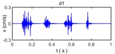
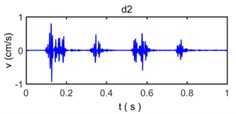
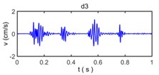
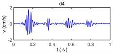
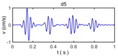
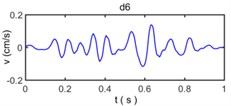
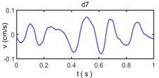
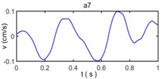
Because wavelet transform always decompose the sub band of the low frequency signal and no longer decompose the sub band of high frequency signal in the process of wavelet analysis, the band range of a7, d7, d6, d5, d4, d3, d2, and d1 is 0-3.9063 Hz, 3.9063-7. 8125 Hz, 7.8125-15.625 Hz, 15.625-31.25 Hz, 31.25-62.5 Hz, 62.5-125 Hz, 125-250 Hz, and 250-500 Hz, respectively. The wavelet component d1 has a very small amplitude reflect the energy of original vibration signal in 250-500 Hz is very small, the wavelet component d2, d3, d4, d5 have observably larger amplitude than other wavelet components which show the energy of original vibration signal in 15.625-250 Hz constitutes a majority of energy of original vibration signal and become main component to influence of building vibration; the wavelet component d6, d7, a7 have less amplitude of original vibration signal reflects the energy of original vibration signal in 0- 15. 625 Hz is also small.
Fig. 10The reconstructed vibration signal and relative error based on wavelet transform
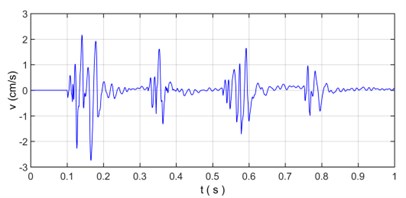
a) Reconstruction signal based on wavelet transform
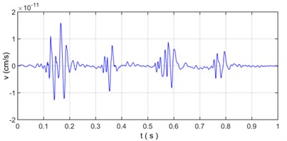
b) Relative error based on wavelet transform
As is shown in Fig. 10, the reconstructed vibration signal based on wavelet transform is very consistently similar to original vibration signal with relative error is 10-11, which shows that wavelet transform can accurately reflect the characteristics of the non-stationary signal and have an excellent suitability for analysis on blasting vibration signal.
Fig. 11 shows power spectrum density of original vibration signal (Fig. 8) and Fig. 12 shows power spectrum density of wavelet component from d1 to d7 and a7 (Fig. 9).
Fig. 11The power spectral density of original vibration signal
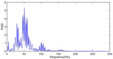
Fig. 11 indicates the blast energy of original vibration signal is mainly within the frequency below 250 Hz region and has three sub-band which varies from 10 Hz to 30 Hz, from 40 Hz to 70 Hz and from 75 Hz to 125 Hz, respectively, in which the main energy concentrates in the range of 40 Hz to 70 Hz, and the energy in the range of 10 Hz to 30 Hz and 75 Hz to 125 Hz is relatively weak.
The natural frequencies of common buildings are between 1 Hz and 10 Hz, from the perspective of security, low energy distribution in the low frequency region is beneficial to structural safety and stability of surrounding rock for reducing the probability of resonance [40, 58].
It can be seen in Fig. 12 that the frequency range about power spectrum density of wavelet component d1 is widely distributed in the range from 220 Hz to 500 Hz and the amplitude of power spectrum density of wavelet component d1 is extremely low. The frequency range of wavelet component d2 mainly varies from 80 Hz to 250 Hz and the corresponding amplitude of power spectrum density is relatively weak. The wavelet component d3, d4, d5 occupies the spectral range from 50 Hz to 120 Hz, from 30 Hz to 80 Hz, and from 15 Hz to 35 Hz, respectively and constitute the main energy of original vibration signal, in addition, the dominant frequency of d6, d7, a7 is below 15 Hz and energy density spectrum is also low.
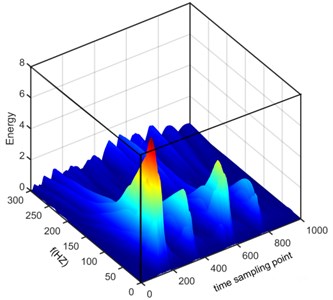
The three-dimensional energy density spectrum of original vibration signal on wavelet transform is showed in Fig. 13.
Fig. 12The power spectrum density of wavelet component from d1 to d7 and a7
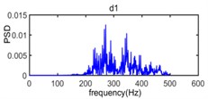
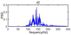
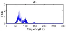
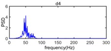
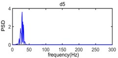
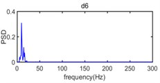
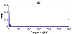
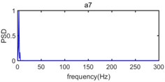
Fig. 13 presented the distribution characteristics about energy of blasting vibration signal as the variation of frequency and time; It can be more intuitive to show the distribution of energy on blasting vibration signal with time and frequency, where the color is redder, the energy is greater, we can see that the energy mainly concentrates on the range of 10 Hz-125 Hz and 100-800 time sampling point, where the main frequency is located at 50 Hz in frequency domain and there are energy peaks near 170, 360, 590 and 780, respectively in the time sampling point. Dividing time sampling point 100-800 by sampling frequency 1000 Hz is 0.10 s-0.80 s, we can obtain the energy mainly concentrates on the range of 10 Hz-125 Hz and 0.10 s-0.80 s. The time frequency distribution characteristics about energy based on Wavelet transform is in accordance with the velocity curve of original vibration signal in Fig. 8 where the time region for velocity vibration amplitude mainly vary from 0.10 s to 0.80 s and there are four velocity amplitude peaks in 0.17 s, 0.36 s, 0.59 s and 0.78 s, respectively and the power spectral density of original vibration signal in Fig. 11 where the frequency region for power spectral density mainly concentrate on 10 Hz-125 Hz where peak of power spectral density is located at 50 Hz.
Fig. 13Time frequency distribution of energy based on Wavelet transform
In the case of wavelet packet analysis for blasting vibration signal, the number of layers of wavelet packet decomposition is needed. The sampling frequency of the blasting vibration signal is determined as 1000 Hz, the Nyquist frequency is 500 Hz on the basis of Shannon sampling theorem [49], According to the principle of wavelet packet analysis, the blasting vibration signal is decomposed to seventh layers, with a total of 27 i.e., 128 wavelet packets and each frequency bandwidth is 3.91 Hz, in which corresponding to the lowest frequency band is 0-3.91 Hz. The frequency bands for the reconstructed signals of each layer after wavelet packet decomposition of the blasting vibration signal are shown in Table 6.
Table 6The range for frequency band of reconstructed signal by wavelet packet decomposition
Number of layers | si,0 (Hz) | si,1 (Hz) | si,2 (Hz) | si,j-1 (Hz) | si,j (Hz) | |
1 | 0-250 | 250-500 | ||||
2 | 0-125 | 125-250 | 250-375 | 375-500 | ||
3 | 0-62.5 | 62.5-125 | 125-187.5 | … | 375-437.5 | 437.5-500 |
4 | 0-31.25 | 31.25-62.5 | 62.5-93.75 | … | 437.5-468.75 | 468.75-500 |
5 | 0-15.63 | 15.63-31.25 | 31.25-46.88 | … | 468.75-484.38 | 484.38-500 |
6 | 0-7.82 | 7.82-15.63 | 15.63-23.44 | … | 484.38-492.19 | 492.19-500 |
7 | 0-3.91 | 3.91-7.82 | 7.82-11.72 | … | 492.19-496.09 | 496.09-500 |
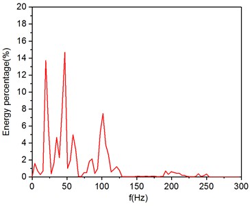
The energy of blasting vibration signal will change in different frequency bands. The vibration signal can be subdivided into different frequency bands by wavelet packet and the corresponding energy in each frequency band can be obtained, which can observably reflects the characteristics of blasting vibration. The calculation in this paper is based on Eqs. (17-20) in MATLAB. The energy of blasting vibration signals is mainly concentrated in 0-300 Hz, so the energy percentage in different frequency bands for the total energy of the signal is shown in Table 7 and Fig. 14.
Table 7The frequency band energy percentage decomposed by wavelet packet decomposition
Frequency band (Hz) | Energy percentage (%) | Frequency band (Hz) | Energy percentage (%) | Frequency band (Hz) | Energy percentage (%) | Frequency band (Hz) | Energy percentage (%) |
0-3.91 | 1.58 | 74.22-78.13 | 0.50 | 148.44-152.34 | 0.09 | 222.66-226.56 | 0.04 |
3.91-7.82 | 0.73 | 78.13-82.03 | 1.83 | 152.34-156.25 | 0.05 | 226.56-230.47 | 0.01 |
7.82-11.72 | 0.26 | 82.03-85.94 | 2.12 | 156.25-160.02 | 0.06 | 230.47-234.38 | 0.05 |
11.72-15.63 | 0.69 | 85.94-89.84 | 0.40 | 160.02-164.06 | 0.09 | 234.38-238.28 | 0.37 |
15.63-19.93 | 13.70 | 89.84-93.75 | 0.96 | 164.06-167.97 | 0.04 | 238.28-242.19 | 0.06 |
19.93-23.44 | 5.77 | 93.75-97.66 | 5.26 | 167.97-171.88 | 0.10 | 242.19-246.09 | 0.14 |
23.44-27.34 | 0.37 | 97.66-101.56 | 7.45 | 171.88-175.78 | 0.08 | 246.09-250.00 | 0.33 |
27.34-31.25 | 1.62 | 101.56-105.47 | 3.80 | 175.78-179.69 | 0.03 | 250.00-253.91 | 0.00 |
31.25-35.16 | 4.64 | 105.47-109.38 | 2.63 | 179.69-183.59 | 0.04 | 253.91-257.81 | 0.00 |
35.16-39.06 | 2.26 | 109.38-113.28 | 0.57 | 183.59-187.50 | 0.07 | 257.81-261.72 | 0.00 |
39.06-42.97 | 7.87 | 113.28-117.19 | 0.88 | 187.50-191.41 | 0.69 | 261.72-265.63 | 0.00 |
42.97-46.88 | 14.67 | 117.19-121.09 | 1.21 | 191.41-195.31 | 0.29 | 265.63-269.53 | 0.00 |
46.88-50.78 | 1.01 | 121.09-125.00 | 0.79 | 195.31-199.22 | 0.62 | 269.53-273.44 | 0.00 |
50.78-54.69 | 1.93 | 125.00-128.91 | 0.03 | 199.22-203.13 | 0.52 | 273.44-277.34 | 0.00 |
54.69-58.59 | 4.96 | 128.91-132.81 | 0.04 | 203.13-207.03 | 0.42 | 277.34-281.25 | 0.00 |
58.59-62.50 | 3.19 | 132.82-136.72 | 0.02 | 207.03-210.94 | 0.43 | 281.25-285.16 | 0.00 |
62.50-66.41 | 0.07 | 136.72-140.63 | 0.02 | 210.94-214.84 | 0.18 | 285.16-289.06 | 0.00 |
66.41-70.31 | 0.03 | 140.63-144.53 | 0.02 | 214.84-218.75 | 0.17 | 289.06-292.97 | 0.00 |
70.31-74.22 | 0.49 | 144.53-148.44 | 0.04 | 218.75-222.66 | 0.05 | 292.97-500.00 | 0.52 |
From Table 7 and Fig. 14, we can see that the energy of the signal between 0 and 250 Hz accounts for 99.48 % of the total energy of the signal, which indicates that although the energy of the blasting vibration signal is widely distributed in the different frequency domain, but most of the energy is concentrated in the range between 0 and 250 Hz. The ratio of the energy of the signal above 250 Hz to the total energy is only 0.52 %, which indicating that the extremely high frequency components (above 250 Hz) of the blasting vibration signal are very few. The energy of the signal in 0-125 Hz accounts for 94.25 % of the total signal and the energy percentage between the 11.72-31.25 Hz, 39.06- 70.31 Hz and 74.22-125 Hz is 22.15 %, 33.73 % and 28.40 %, respectively, this phenomenon reflect that the dominant energy of the millisecond delay blasting vibration signal is mainly distributed in the main frequency band, and the main frequency band can be divided into multiple sub frequency band.
Fig. 14The frequency band energy percentage of vibration signal
3.4. Initiative control for blasting vibration effect
Blasting vibration effect is affected by the blasting design parameters, topography parameters and geology parameters, where the blasting design parameters include the explosive charge, explosive distance, hole-pattern parameters, charging structure, initiation method, and millisecond blasting delay time; topography parameters contain subdued topography, concave topography, convex topography and inclination topography; geology parameters involve rock property, rock structure, fault distribution , and hydrological conditions, etc. In this study, the initiative control for blasting vibration effect is mainly by controlling maximum explosive weight per delay and total explosive weight, meanwhile, adopting decoupling charge and millisecond delay blasting technology; in which the emulsion explosive has a diameter of 32 mm, diameter of hole is 90 mm or 115 mm, therefore, the radial uncoupling coefficient of about 2.81 or 3.59; in addition, four multiple section of non-electric shock tube delay detonator is usually used with millisecond connector.
Fig. 15The dominant frequency distributions of all particle velocity
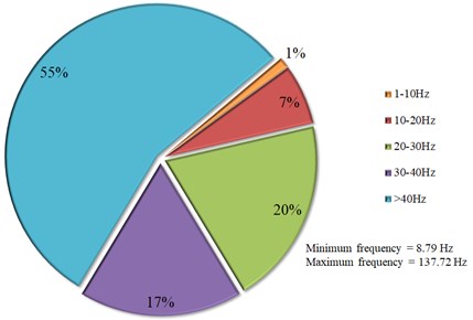
The dominant frequency distributions of all particle velocity are given in Fig. 15. This graph shows that the percentage distribution of blasting vibration signal is 1 %, 7 %, 20 %, 17 % and 55 % when dominant frequency distribution varies from 1-10 Hz, 10-20 Hz, 20-30 Hz, 30-40 Hz and above 40 Hz, in which the maximum frequency and minimum frequency is 137.72 Hz and 8.79 Hz, respectively.
In consistent with the standards of the United States Bureau of Mines (USBM), Siskind et al. [59] point out damage potentials for low-frequency blasts (< 40 Hz) are considerably higher than those for high-frequency blasts (> 40 Hz), with the latter often produced by close-in construction and excavation blasts. A major part of the recorded dominant frequencies is greater than 40 Hz, hence, it can be said that the blasting site of foundation excavation can be classified as a moderate -frequency site. Because the natural frequencies of common buildings are between 1 Hz and 10 Hz, the ratio of vibrations with dominant frequencies of lower than 10 Hz only is 1 %, it is difficult to produce resonance phenomenon, which is beneficial to the safety of structure and rock mass [40, 58].
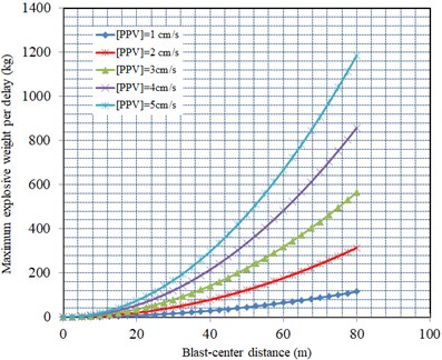
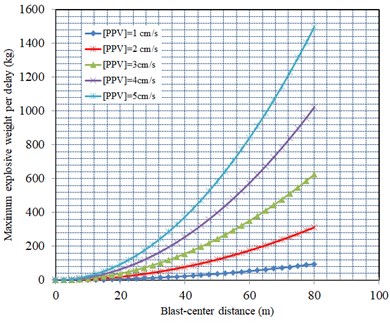
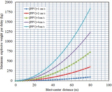
In order to perform controlled blasting, the relationship between the maximum explosive weight per delay and the blast-center distance at different maximum allowable PPVlimit can be calculated as Fig. 16. It is able to determine maximum charge weight per delay for any shot in close distances to the road corridor.
Fig. 16The relationship between maximum explosive weight per delay and the distance on account of different PPVlimit
a) Horizontal radial direction
b) Horizontal tangential direction
c) Vertical direction
It is very significant of setting the initiative control standard of particle vibration velocity for new pouring concrete and surrounding rock mass. “Safety regulations for blasting” (GB6722-2014) points out the permitted particle vibration velocity is subject to the maximum value of three mutually perpendicular components in cartesian coordinate of blasting vibration signal and the vibration frequency is the dominant frequency of permitted particle vibration velocity. The road corridor belongs to new pouring mass concrete with concrete strength grade of C50 and curing time has been over 28 days at the start of blasting for foundation excavation of road corridor project, as for the measured vibration data, the dominant frequency of the blasting vibration signal is mainly in 10 Hz-100 Hz, the safe allowable velocity standard in “Safety regulations for blasting” (GB6722-2014) is 7.0-12.0 cm/s, in order to more safe, the safe allowable peak particle velocity of 5.0 cm/s is recommended in this paper. In terms of the safety criterion of peak vibration velocity for the blasting damage of rock mass, the lithologic types of bedrock are slightly weathered calcareous conglomerate, sandy conglomerate and siltstone [60], which should belong to intact rock, Bauer A. [54] point out that there is no fracturing damage of intact rock for blasting excavation when peak particle velocity is under 25.0 cm/s, as a conservative approach, a PPV of 5.0 cm/s was adopted as bedrock safe vibration level for safely completing the road corridor excavation work. Therefore, the initiative control standard of particle vibration velocity for new pouring mass concrete and bedrock in road corridor are both determined to [PPV] = 5.0 cm/s according to Table 1 of “Safety regulations for blasting” (GB6722-2014) and expert opinion.
As seen in the Table 5, in terms of the peak particle velocity of 20 groups monitoring data, Due to the phenomenon about field monitoring particle vibration velocity approximate close to initiative control standard of particle vibration velocity is existed, therefore, we should control maximum explosive weight per delay at different distance from the explosion source on the basis of the blast-induced peak particle velocity attenuation law based on Eq. (22-24) and Fig. 16. As shown in Table 8, the maximum explosive weight per delay is controlled by maximum explosive weight per delay of horizontal radial direction. If the distance between road corridor monitoring point and the explosion source is 30 m, the maximum explosive weight per delay can be evaluated to 166.8 kg; that is, it can satisfy the road corridor concrete structure and rock mass safety when the maximum explosive weight per delay is less than 166.8 kg. In order to guarantee safety of damage control for new pouring mass concrete and bedrock in road corridor under blasting load in Xianning Nuclear Power Station, it is essential that we should strictly control maximum explosive weight per delay and total explosive weight based on above calculation results of Table 8 and Fig. 16.
The peak particle velocity and frequency of the total 252 blasting vibration data along the horizontal radial, horizontal tangential and vertical direction were recorded from 84 blasting monitoring points of 19 shots in new pouring mass concrete and bedrock at road corridor were evaluated. The evaluation of damage risk of the blasts on new pouring mass concrete and bedrock is shown in Fig. 17. It was observed in Fig. 17 that the recorded peak particle velocity for nearly all blasts were below allowable limit of PPV (5 cm/s) for new pouring mass concrete with curing time over 28d and bedrock.
Fig. 17Evaluation of damage risk of the blasts on new pouring mass concrete and bedrock
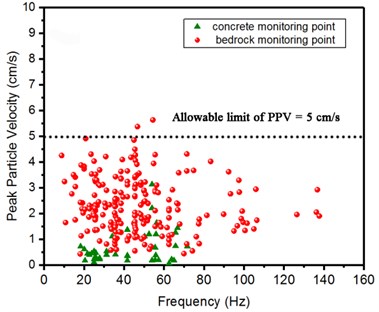
Table 8The maximum explosive weight per delay calculated by Eq. (22) to Eq. (24)
Blast radial distance (m) | Horizontal radial direction | Horizontal tangential direction | Vertical direction | Maximum explosive weight per delay(kg) |
Qx(kg) | Qy(kg) | Qz(kg) | ||
10 | 18.5 | 23.4 | 28.7 | 18.5 |
20 | 74.1 | 93.5 | 114.7 | 74.1 |
30 | 166.8 | 210.4 | 258.1 | 166.8 |
40 | 296.5 | 374.1 | 458.9 | 296.5 |
50 | 463.3 | 584.5 | 717.0 | 463.3 |
60 | 667.1 | 841.7 | 1032.5 | 667.1 |
4. Conclusions
The peak particle velocity attenuation law are investigated through regression analysis of practical field data by Duvall empirical formula and the time-frequency characteristics was analyzed by wavelet transform and wavelet package decomposition at a road corridor in Xianning Nuclear Power; The dominant frequency distributions of all particle velocity are presented, the relationship between maximum explosive weight per delay and the distance on account of different PPVlimit are given. In order to reduce the damage extent to the new pouring mass concrete and surrounding rock mass, some initiative control methods for blasting vibration effect is carried out. The main conclusions of the study are drawn as follows:
1) The peak particle velocity attenuation law along the horizontal radial, horizontal tangential and vertical direction is expressed as PPVx=16.0(SD)-1.38, PPVy=11.7(SD)-1.17, PPVz=10.0(SD)-1.11, respectively. Based on the above equation, we can effectively present the blasting design about the maximum explosive weight per delay, Q, according to the allowable peak particle velocity, PPVlimit, at different distance from the center of explosion, R, in terms of requisition of “Safety regulations for blasting” (GB6722-2014) and expert opinion in China, which shows the excellent control effect on blasting damage of the new pouring mass concrete and surrounding rock mass.
2) As for measured data, By analyzing the velocity amplitude and power spectrum density amplitude of wavelet components, it shows the energy of original vibration signal in 250-500 Hz is very small, the blast energy of original vibration signal is mainly within the frequency below 250 Hz region and has three sub-band which varies from 10 Hz to 30 Hz, from 40 Hz to 70 Hz and from 75 Hz to 125 Hz, respectively, in which the main energy concentrates in the range of 40 Hz to 70 Hz, and the energy in the range of 10 Hz to 30 Hz and 75 Hz to 125 Hz is relatively weak. Wavelet packet analysis indicates the energy of the signal in 0-125 Hz accounts for 94.25 % of the total signal and the energy percentage between the 11.72-31.25 Hz, 39.06-70.31 Hz and 74.22-125 Hz is 22.15 %, 33.73 % and 28.40 %, respectively.
3) The initiative control for blasting vibration effect is mainly by controlling maximum explosive weight per delay and total explosive weight, meanwhile, adopting decoupling charge and millisecond delay blasting technology; in which the initiative control standard of particle vibration velocity for new pouring mass concrete and bedrock in road corridor both is determined to [PPV] = 5.0 cm/s, the radial uncoupling coefficient of about 2.81 or 3.59, four multiple section of non-electric shock tube delay detonator is usually used with millisecond connector. the recorded peak particle velocity for nearly all blasts were below allowable limit of PPV for new pouring mass concrete with curing time over 28d and bedrock.
References
-
Wang Z. W., Li X. B., Peng K., et al. Impact of blasting parameters on vibration signal spectrum: Determination and statistical evidence. Tunnelling and Underground Space Technology, Vol. 48, Issue 1, 2015, p. 94-100.
-
Torres V. F., Silveira L. G., Lopes P. F., et al. Assessing and controlling of bench blasting-induced vibrations to minimize impacts to a neighboring community. Journal of Cleaner Production, Vol. 187, Issue 1, 2018, p. 514-524.
-
Yan Y., Hou X. M., Fei H. L. Review of predicting the blast-induced ground vibrations to reduce impacts on ambient urban communities. Journal of Cleaner Production, Vol. 260, Issue 1, 2020, p. 1-21.
-
Ainalis D., Ducarne L., Kaufmann O., et al. Improved analysis of ground vibrations produced by man-made sources. Science of The Total Environment, Vol. 616, Issue 1, 2018, p. 517-530.
-
Murmu S., Maheshwari P., Verma H. K. Empirical and probabilistic analysis of blast-induced ground vibrations. International Journal of Rock Mechanics and Mining Sciences, Vol. 103, Issue 1, 2018, p. 267-274.
-
Singh P. K., Roy M. P. Damage to surface structures due to blast vibration. International Journal of Rock Mechanics and Mining Sciences, Vol. 47, Issue 6, 2010, p. 949-961.
-
Zhang C. S., Hu F., Zou S. Effects of blast induced vibrations on the fresh concrete lining of a shaft. Tunnelling and Underground Space Technology, Vol. 20, Issue 4, 2005, p. 356-361.
-
Sun X. M., Wang J. Y. Evaluation of blasting vibration effects on buildings. Blasting, Vol. 25, Issue 2, 2008, p. 73-76.
-
Deng T., Jin Y. P., Wu P. G., et al. Highway tunnel blasting vibrations and cracking of adjacent residential houses. Modern Tunnelling Technology, Vol. 55, Issue 3, 2018, p. 69-75.
-
Jiang D. Y., Hou Y. B., Ren S., et al. Study on the influence of urban large-span tunnel blasting on ground buildings. China Safety Science Journal, Vol. 18, Issue 7, 2008, p. 99-104.
-
Li H. B., Xia X., L. J. C., et al. Rock damage control in bedrock blasting excavation for a nuclear power plant. International Journal of Rock Mechanics and Mining Sciences, Vol. 48, Issue 2, 2011, p. 210-218.
-
Zeng Y. Q., Li H. B., Xia X., et al. Blast-induced rock damage control in Fangchenggang nuclear power station, China. Journal of Rock Mechanics and Geotechnical Engineering, Vol. 10, Issue 5, 2018, p. 914-923.
-
Li X. F., Li H. B., Zhang G. K. Damage assessment and blast vibrations controlling considering rock properties of underwater blasting. International Journal of Rock Mechanics and Mining Sciences, Vol. 121, Issue 1, 2019, p. 104045.
-
Nateghi R. Prediction of ground vibration level induced by blasting at different rock units. International Journal of Rock Mechanics and Mining Sciences, Vol. 48, Issue 6, 2011, p. 899-908.
-
Nateghi R. Evaluation of blast induced ground vibration for minimizing negative effects on surrounding structures. Soil Dynamics and Earthquake Engineering, Vol. 43, Issue 1, 2012, p. 133-138.
-
Li P., Lu W. B., Wu X. X., et al. Spectral prediction and control of blast vibrations during the excavation of high dam abutment slopes with millisecond-delay blasting. Soil Dynamics and Earthquake Engineering, Vol. 94, Issue 1, 2017, p. 116-124.
-
Qiu X. Y., Shi X. Z., Gou Y. G., et al. Short-delay blasting with single free surface: results of experimental tests. Tunnelling and Underground Space Technology, Vol. 74, Issue 1, 2018, p. 119-130.
-
Faramarzi F., Farsangi M. A., Mansouri H. Simultaneous investigation of blast induced ground vibration and airblast effects on safety level of structures and human in surface blasting. International Journal of Mining Science and Technology, Vol. 24, Issue 5, 2014, p. 663-669.
-
Ak H., Konuk A. The effect of discontinuity frequency on ground vibrations produced from bench blasting: A case study. Soil Dynamics and Earthquake Engineering, Vol. 28, Issue 9, 2008, p. 686-694.
-
Ak H., Iphar M., Yavuz M., et al. Evaluation of ground vibration effect of blasting operations in a magnesite mine. Soil Dynamics and Earthquake Engineering, Vol. 29, Issue 4, 2009, p. 669-676.
-
Simangunsong G. M., Wahyudi S. Effect of bedding plane on prediction blast-induced ground vibration in open pit coal mines. International Journal of Rock Mechanics and Mining Sciences, Vol. 79, Issue 1, 2015, p. 1-8.
-
Shin J. H., Moon H. G., Chae S. E. Effect of blast-induced vibration on existing tunnels in soft rocks. Tunnelling and Underground Space Technology, Vol. 26, Issue 1, 2011, p. 51-61.
-
Yu H. T., Yuan Y., Yu G. X., et al. Evaluation of influence of vibrations generated by blasting construction on an existing tunnel in soft soils. Tunnelling and Underground Space Technology, Vol. 43, Issue 1, 2014, p. 59-66.
-
Xia X., Li H. B., Li J. C., et al. A case study on rock damage prediction and control method for underground tunnels subjected to adjacent excavation blasting. Tunnelling and Underground Space Technology, Vol. 35, Issue 1, 2013, p. 1-7.
-
Gou Y. G., Shi X. Z., Zhou J., et al. Attenuation assessment of blast-induced vibrations derived from an underground mine. International Journal of Rock Mechanics and Mining Sciences, Vol. 127, Issue 1, 2020, p. 104220.
-
Singh P. K., Roy M. P., Paswan R. K., et al. Blast vibration effects in an underground mine caused by open-pit mining. International Journal of Rock Mechanics and Mining Sciences, Vol. 80, Issue 1, 2015, p. 79-88.
-
Roy M. P., Singh P. K., Sarim M. D., et al. Blast design and vibration control at an underground metal mine for the safety of surface structures. International Journal of Rock Mechanics and Mining Sciences, Vol. 83, Issue 1, 2016, p. 107-115.
-
Jiang N., Zhou C. B., Lu S. W., et al. Propagation and prediction of blasting vibration on slope in an open pit during underground mining. Tunnelling and Underground Space Technology, Vol. 70, Issue 1, 2017, p. 409-421.
-
Li X. B., Zhang Y. P., Liu Z. X., et al. Wavelet analysis and Hilbert-Huang transform of blasting vibration signal. Explosion and Shock Waves, Vol. 25, Issue 6, 2005, p. 528-535.
-
Xu G. Y., Zhong G. S., Xiong Z. M. Study and application of energy analysis method for blasting seismic safety based on wavelet transform. Chinese Journal of Geotechnical Engineering, Vol. 28, Issue 1, 2006, p. 24-28.
-
Zhong G. S., Li J., Zhao K. Structural safety criteria for blasting vibration based on wavelet packet energy spectra. Mining Science and Technology (China), Vol. 21, Issue 1, 2011, p. 35-40.
-
Zhong G. S., Ao L. P., Zhao K. Influence of explosion parameters on wavelet packet frequency band energy distribution of blast vibration. Journal of Central South University, Vol. 19, Issue 1, 2012, p. 2674-2680.
-
Zhao M. S., Zhang J. H., Yi C. P. Time–frequency characteristics of blasting vibration signals measured in milliseconds. Mining Science and Technology (china), Vol. 21, Issue 3, 2011, p. 349-352.
-
Han B., Ma Q. Y. Wavelet packet analysis of energy distribution features of blasting vibration signals in coal mine rock roadway. China Mining Magazine, Vol. 22, Issue 6, 2013, p. 110-113.
-
Shi X. Z., Qiu X. Y., Zhou J., et al. Application of Hilbert-Huang transform based delay time identification in optimization of short millisecond blasting. Transactions of Nonferrous Metals Society of China, Vol. 26, Issue 7, 2016, p. 1965-1974.
-
Li X. L., Li Z. H., Wang E. Y., et al. Analysis of natural mineral earthquake and blast based on Hilbert–Huang transform (HHT). Journal of Applied Geophysics, Vol. 128, Issue 1, 2016, p. 79-86.
-
Lu W. B., Lai S. X., Zhu C. Y., et al. Safety standards of blast vibrations adopted in rock base excavation of three gorge project. Explosion and Shock Waves, Vol. 21, Issue 1, 2001, p. 67-71.
-
Lu W. B., Li H. B., Chen M., et al. Safety criteria of blasting vibration in hydropower engineering and several key problems in their application. Chinese Journal of Rock Mechanics and Engineering, Vol. 28, Issue 8, 2009, p. 1513-1520.
-
Lu S. H., Zhou C. B., Jiang N., et al. Effect of excavation blasting in an under-cross tunnel on airport runway. Geotechnical and Geological Engineering, Vol. 33, Issue 3, 2015, p. 973-981.
-
Li X. B., Ling T. H., Zhang Y. P. Analysis of Blast Vibration Signals Theories and Methods. Science Press, Beijing, 2009.
-
Duvall W. I., Fogelson D. E. Review of Criteria for Estimating Damage to Residences from Blasting Vibration. Report No. R.I. 5968, United States Bureau of Mines, Washington, 1962.
-
Langefors U., Kihlstrom B. The Modern Technique of Rock Blasting. John Wiley and Sons, New York, 1963.
-
IS 6922. Criteria for Safety and Design of Structures Subject to Underground Blast. Bureau of Indian Standards (BIS), New Delhi, India, 1973.
-
Pal Roy P. Vibration control in an opencast mine based on improved blast vibration predictors. Mining Science and Technology, Vol. 12, Issue 2, 1991, p. 157-165.
-
GB6722-2014. Safety Regulations for Blasting. Standards Press of China, Beijing, 2014, (in Chinese).
-
Kumar R., Choudhury D., Bhargava K. Determination of blast-induced ground vibration equations for rocks using mechanical and geological properties. Journal of Rock Mechanics and Geotechnical Engineering, Vol. 8, Issue 3, 2016, p. 341-349.
-
Blair D. P. Blast vibration dependence on charge length, velocity of detonation and layered media. International Journal of Rock Mechanics and Mining Sciences, Vol. 65, Issue 1, 2014, p. 29-39.
-
Tripathy G. R., Shirke R. R., Kudale M. D. Safety of engineered structures against blast vibrations: A case study. Journal of Rock Mechanics and Geotechnical Engineering, Vol. 8, Issue 2, 2016, p. 248-255.
-
Zhang D. F. Wavelet analysis. China Machine Press, Beijing, 2011.
-
Pei L., Liu J., Guinness R., et al. Using LS-SVM Based Motion Recognition for Smartphone Indoor Wireless Positioning. Sensors, Vol. 12, Issue 5, 2012, p. 6155-6175.
-
Wang X. G., Yu Y. L. On several problems of safety criterion of blasting vibration. Engineering Blasting, Vol. 7, Issue 2, 2001, p. 88-92.
-
Zhang J. C. Vibration characteristics of blasting in bed rock mass at Three Gorges project. Explosion and Shock Waves, Vol. 21, Issue 2, 2001, p. 131-137.
-
Huang Z. P., Song Y. L. Effect and control of the blast for the remnant rock mass. Journal of Wuhan Automotive Polytechnic University, Vol. 21, Issue 6, 1999, p. 90-94.
-
Bauer A., Calder P. N. Open pit and blast seminar. Mining Engineering Department, Kingston, Ontario, Canada, 1978.
-
Mojtabai N., Beattie S. G. Empirical approach to prediction of damage in bench blasting. Transactions of the Institution of Mining and Metallurgy, Vol. 105, Issue 1, 1996, p. 75-80.
-
Wang X. F. Selection and Optimization of Wavelet Base. Journal of Zhuzhou Institute of Technology, Vol. 17, Issue 5, 2003, p. 33-35.
-
Wang H. B. Study on Roadway Stability and Control of Blasting Seismic Effect in Coal Mine. Ph.D. Thesis, Anhui University of Science and Technology. Huainan, China, 2012.
-
Zong Q., Wang H. B., Zhou S. B. Research on monitoring and controlling techniques considering effects of seismic shock. Chinese Journal of Rock Mechanics and Engineering, Vol. 27, Issue 5, 2008, p. 938-945.
-
Siskind D. E., Stagg M. S., Kopp J. W., Dowding C. H. Structure response and damage produced by ground-vibration from surface mine blasting. Report No. RI 8507, Washington, United States Bureau of Mines; 1980.
-
Li W. Q. Geotechnical characteristics of the upper cretaceous -tertiary at dafan nuclear power plant of tongshan county in hubei. Resources and Environment Engineering, Vol. 20, Issue 1, 2006, p. 32-35.
Cited by
About this article
The study was supported by the Key Program of National Natural Science Foundation of China (Grant No. 51439008), National Natural Science Foundation of China (Grant Nos. 41572307 and 51779248), and The Program of Hunan Province Education Department of China under (Grant No. 19C0870). The authors are also very grateful to the editors and anonymous reviewers for valuable suggestions which have improved the quality of this paper.

