Abstract
The interest to use steel foam sandwich structures is expanding in various industrial applications, and more attention is paid to improve the properties of these materials. However, liquid and solid intrusions can severely hamper their useful characteristics. This study aims to provide an experimental investigation on the potential of steel foam (hollow sphere) sandwich specimens to operate as passive dampers in flexural vibration and to preserve their capabilities when affected by the intrusion of external particles. The authors utilized two different experimental examinations, random noise (white noise) and impact (hammer) tests. The specimens consist of a hollow sphere foam core sandwiched between two mild steel sheets, bonded with a thermosetting epoxy resin. To simulate the intrusions of granular materials in operating conditions, the metallic foam cores of the samples were partially filled with different percentages of quartz sand particles. The two-phase specimens were then compared to the pristine (single-phase) ones. The resulting estimates of the vibrational damping ratio for single and double-phase metallic foam specimens were used to calibrate the respective Finite Element models, which proved to be suitable for replicating the damping characteristics of the specimens.
Highlights
- The dynamic properties of metallic foam sandwich panels are experimentally investigated.
- Their performances as passive dampers are determined with and without sand intrusions.
- Frequency Response Functions both from the Random Noise and Impact Tests are used to calibrate the Finite Element models of the specimens.
1. Introduction
In the last few years, the growing demand to detect new structures with better mechanical properties and lower weight gave the direction to improve and employ novel foam sandwich elements [1]. These can be made by diverse materials mixtures. Specifically, metallic foams are made up of two thin sheets (skins) enclosing a central core to which they can be linked with different methods, e.g., bonded together [2, 3], to support the load and pressure between its components [4]. Table 1 provides a brief overview of some noteworthy uses.
Table 1Potential applications for metallic foam
Applications | Importance to engineering |
Wind turbine tower | Great specific stiffness, perfect shear strength, and low density |
Off-shore structures | Damping capability, vibration frequency tuning |
Aircraft structures (e.g., B787) | Low weight, high stiffness, damping capability, vibration frequency tuning, higher lifetime |
Marin structures | High stiffness/weight ratio |
Automotive | high stiffness, energy absorption, damping insulation |
Nowadays, metallic foam materials are still relatively novel and characterized inadequately, though, they have developed quickly since the last decade and using as a new type of porous material [5]. Moreover, these ultra-lightweight materials have special physical and mechanical characteristics, such as high specific stiffness, fireproofing, ideal plastic energy absorption (low weight), good permeability, high damping ratio together with excellent resistance against corrosion, etc. [6, 7]. These unique structures have a mixture of properties that cannot be reached by using metals (solids), dense polymers, or ceramic foams. For instance, the energy absorption and mechanical strength of these materials are higher than the polymer foams [8, 9]. The metallic foams’ mechanical and structural characteristics are defined based upon cell topology (suchlike an open or closed cell), the relative density of the bulk foam ( is the foam density and the is the solid density), size and volume, foaming material, and its anisotropy [1, 10]. Moreover, being nontoxic and have the potential to recycle are other main factors for these unique materials together with high resistance to explosion and impact force more than the regular structures considering the equal mass [11-13].
Even though metallic foams have large potential and various applications in different industrial sectors, they are not yet enough extensively used and widespread [14]. It is expected, in the next following years, the accessibility of metallic foams will increase expeditiously due to intensive research investigation and advancing processes [15].
The inspiration for this study formed on the hypothesis that metallic foam materials are a new and unique kind of composites, which can perfectly use as the ultra-light stiffened structures against buckling, and capable to mitigate vibrations in various civil and mechanical demands together with some other infrastructures suchlike bridges, wind turbine towers [16], offshore structures, aerospace, and armour for both military and civil applications [17, 18]. However, these properties may suffer from degradation over time, especially due to the presence of external objects (solid or liquid) into the cavities of the core. This is a potential threat especially for applications in the oil and gas industry, which often operates in desert regions or offshore and are subject to oil leakages. Even small surface cracks may cause large intrusions. While many progressions have been made in recent years for damage detection and localization – e.g. [19-22] small crack may still go undetected, especially in hard-to-reach locations (e.g., foundations or underwater structures). For all these reasons, at the current time, it is needed to pre-emptively account for potential liquid and solid intrusions, thus characterizing the sandwich panels for that contingency.
Although there are several existing manufacturing methods, three main production methods to make metallic foam materials can be listed as:
1) Hollow spheres: it has applied successfully in different profitable products and the most proper technique for the present research study,
2) Powder metallurgy [23]: it is using sufficiently to improve structural metallic foams,
3) Lotus: it has a high capacity for processing continuously at a low-cost [5].
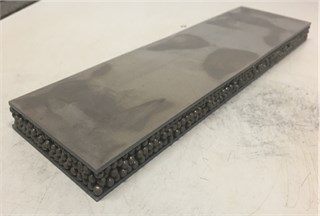
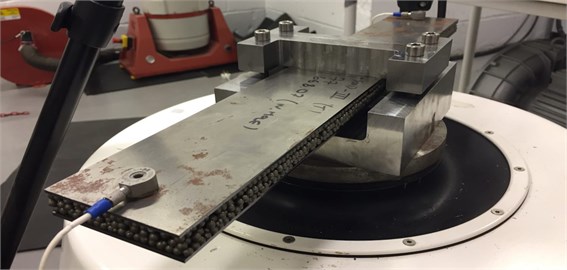
Currently, around 150 companies are producing and working on different metallic foams in the world. They are developing these materials to use in various industrial applications suchlike lightweight structures, blast-resistance structures, energy absorption, heat exchangers, and biomedical implants [24]. This study focused on the hollow sphere; specifically, it was performed on plate-like samples like the one represented in Fig. 1. The specimens were manufactured by Hollomet and coated by thermosetting epoxy Araldite AT1-1 (epoxy adhesive in powder kind) to connect the core with the two light steel faceplates.
Fig. 1Hollomet specimen
The physical and mechanical characteristics estimation of metallic-foam materials is an inevitable discussion. The mechanical properties of steel foam manufactured by the different processes are available in the literature [25]. A model to express the properties of metallic foams was proposed by Gibson and Ashby [5], which could provide the scaling relationships for foams characteristics [26].
In this sense, the scientific literature about the characterization of metal foam structural components is quite large; experimental analyses are fundamental in the investigation of composite material damping [27]. Lim et al. [10] studied the quasi-static uniaxial compression behaviour of both single hollow spheres and bulk metal foams. Ramamurty and Paul [28] discussed the dependence of the macroscopic mechanical properties as a function of relative density. A complete review can be found in the work of Patel et al. [1]. However, the static examination and analysis of stress and strain are not enough to fully characterize the dynamic response of the target structure. Consequently, vibration analysis is fundamental. Regarding specifically their dynamic behaviour, Jing et al. [29] experimentally investigated sandwich beam-like panels, while Vaidya et al. [30] focused on the impact and post-impact vibrations for sandwich plates. The identification of the structural damping was studied by Tu and Wang [31] with an analytical approach.
The other aim of this research was to obtain a calibrated FE model of the investigated specimens. Since metallic-foam structures are extremely engineered materials, applying finite element models is an economical and effective way to understand the behaviour of these novel materials. One of the main remarkable properties of the metallic-foams is relative density and there are several mathematical models and numerical analysis which intend to define material behaviour due to this feature, though, the experimental analysis represents the properties of metallic-foam materials are more complex than the current mathematical representations [26]. The existence of errors between the experimental outcomes and numerical results can negatively affect the maintenance, design, and repair of the structures. Consequently, to solve the complexities caused by the experiment and the simulation, a detailed FEM is required [32].
The rest of this paper is organized as follows. The experimental set-up and the two typologies of specimens are described in Section 2. The FE Model Updating procedure is briefly recalled in Section 3. The Results are commented on in Section 4, and the Conclusions are reported in Section 5.
2. Experimental set-up
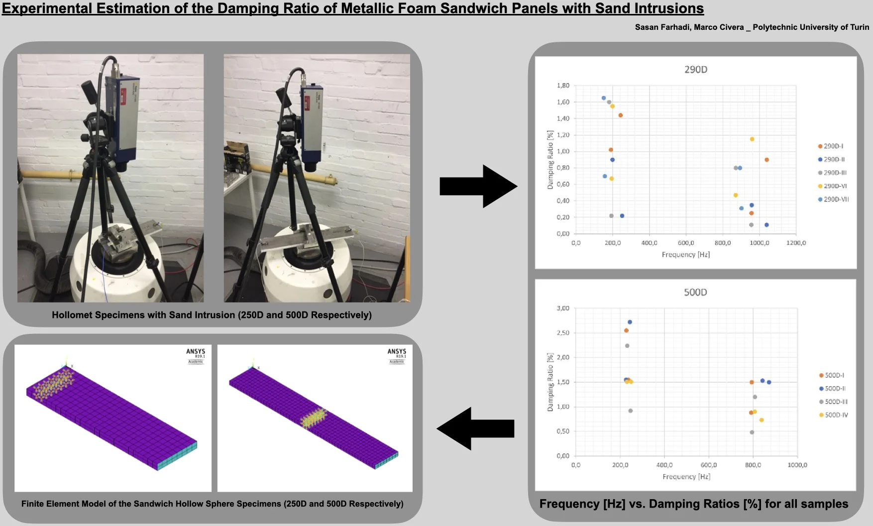
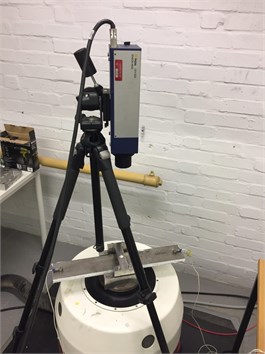
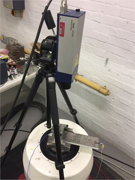
Two typologies of panels were considered: a single-cantilever form (length 290 mm) with the code 290D, and a 500 mm-long double-cantilever shape with an intermediate clamp at mid-length (labelled 500D). Both specimens had a 23.5 mm span. Four 500D and five 290D samples have been investigated experimentally. They have been clamped to the shaker (a V400HG/DSA4 Data-Physics electrodynamic vibration exciter) by applying around 20 N∙m torque due to hold two blocks and minimize the friction damping. Moreover, SignalStar Vibration Controller has been given the shaker closed-loop control together with the corresponding control and analysis software. Both a laser Doppler vibrometer (LDV; Polytec OFV-505) and PCB piezoelectric accelerometers (shown in Fig. 2) have been applied to measure the output from the samples’ tip.
The two different experimental procedures mentioned above (Random Noise and Impact test) have been performed. Table 2 reports the specific details of the Solid Foam Specimens (SFS). The acquisition set-up has been the same for all the examinations, using a signal acquisition module NI-9234 (four-channel) from National Instrument and LabView software. A sampling frequency of 1024 Hz was set for the LDV.
For what concerns the Random Noise tests, an amplitude of 0.0025 g/Hz was applied to all specimens. The bandwidth was set to 30 to 2000 Hz for the 500D specimens, and 30 to 2500 Hz for the 290D specimens. To eliminate the small shaker displacements that occurred during the test, the low frequencies (< 30 Hz) have been filtered out. There were no vibrational modes under this threshold, so it was an appropriate assumption. The impact test procedure has been defined by the trial-and-error approach, the selected parameters (equal for all specimens) were a time length of 3 ms and 20 g for the peak amplitude. The laser vibrometer has been used to read the response of the specimen and the input signal has been recorded by the feedback accelerometer.
Fig. 2Test set-ups: a) the Hollomet Specimen 500D (clamped in the middle) with sand intrusion, b) the Hollomet Specimen 290D (clamped on one end) with sand intrusion, c) detail view of the 500D with the attached sensors
a)
b)
c)
Table 2Specimen geometry and sand volume
Specimen code | Length [mm] | Sand volume [mL] |
SFS4-500D-I | 500 | 20 |
SFS4-500D-II | 500 | 20 |
SFS4-500D-III | 500 | 0 |
SFS4-500D-IV | 500 | 0 |
SFS4-290D-I | 290 | 20 |
SFS4-290D-II | 290 | 0 |
SFS4-290D-III | 290 | 0 |
SFS4-290D-VI | 290 | 20 |
SFS4-290D-VII | 290 | 20 |
3. FE modeling and model calibration
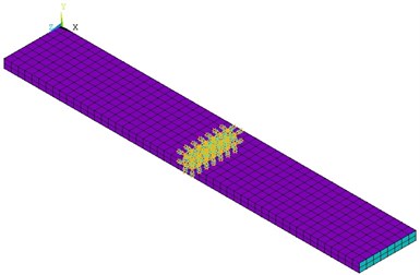
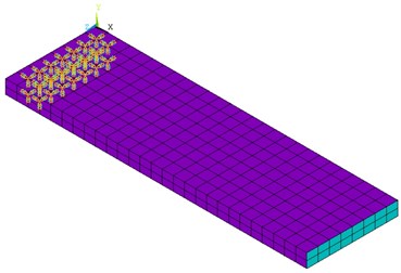
To replicate the damping characteristics of the metal-foam materials for the FEM analysis, FE models were built by using the commercial ANSYS Mechanical software (free Academic version, V.19.1). These reflect the sandwich geometry, with the core and the face-sheet modelled respectively as solid and shell elements (the models are not intended to be a high-fidelity geometrical model but to capture the vibrational global behaviour). Fig. 3 shows the finite element model for both 500D and 290D specimens. The constraint has been fixed on the peak and base of the clamped cross-section.
Fig. 3Finite element model of the sandwich hollow sphere specimen: a) Specimen 500D; b.) Specimen 290D
a)
b)
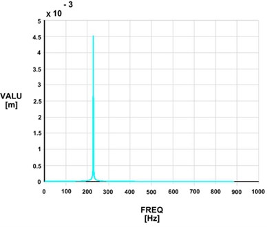
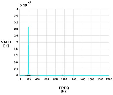
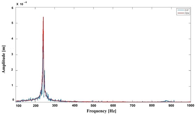
Table 3 represents the material features set in the numerical models. The mesh was formed by 1020 Elements (1900 Elements for the specimen 500D) and 756 nodes (1404 nodes for the specimen 500D) to have a relevant deformation control. Both harmonic and modal analyses were performed on the models, iteratively, to update and calibrate the values of the damping ratio [33, 34]. This was done accordingly to the model updating procedure described in [35] and more recently applied in [36, 37]. This is based on the fitting of the numerically defined Frequency Response Function (FRF) over the experimental input-output acquisitions. The nodes closer to the actual sensor placement were considered for this aim. Fig. 4 shows an example of the results collected from the numerical simulation, while Fig. 5 highlights the fitting procedure over the displacement.
Table 3Specimen material properties data
Specimen unit | Density | Poisson’s ratio | Young’s modulus |
Solid shell | 7800 kg/m3 | 0.3 | 210 GPa |
Core | 450 kg/m3 | 0.1 | 560 MPa |
Fig. 4Harmonic response analysis for the numerically simulated sandwich specimen: a) Specimen 500D; b) Specimen 290D
a)
b)
4. Results
The modal parameters as experimentally estimated for each specimen are reported in Table 4 for random noise and Table 5 for the impact test. The resulting natural frequencies and damping ratios are plotted in Fig. 5 for the reader’s convenience.
Fig. 5FEM vs. EXP results
The results were further confirmed by the second round of experiments (run only on one 500D specimen) with a Polytec 3D laser vibrometer, performing a multi-point sweep sine scan from 100 to 2000 Hz. Two undetected torsional modes were also found in between the two flexural modes at circa 577 Hz and circa 645 Hz respectively. The following mode encountered was a third flexural shape at circa 1620 Hz; however, this was deemed of less practical interest due to its natural frequency.
Table 4Random noise tests outputs
Specimen code | Frequency [Hz] | Damping ratio [%] | Frequency [Hz] | Damping ratio [%] |
SFS4-500D-I | 227.7 | 2.55 | 793.9 | 1.50 |
SFS4-500D-II | 243.6 | 2.72 | 871.9 | 1.50 |
SFS4-500D-III | 231.8 | 2.24 | 808.5 | 1.20 |
SFS4-500D-IV | 248.7 | 1.51 | 838.6 | 0.73 |
SFS4-290D-I | 190.6 | 1.02 | 956.1 | 0.25 |
SFS4-290D-II | 250.9 | 2.20 | 1039.1 | 0.11 |
SFS4-290D-III | 192.4 | 2.20 | 955.2 | 0.11 |
SFS4-290D-VI | 193.7 | 0.67 | 870.4 | 0.47 |
SFS4-290D-VII | 156.2 | 0.70 | 902.0 | 0.31 |
Table 5Impact tests outputs
Specimen code | Frequency [Hz] | Damping ratio [%] | Frequency [Hz] | Damping ratio [%] |
SFS4-500D-I | 236.6 | 1.55 | 791.2 | 0.88 |
SFS4-500D-II | 226.3 | 1.55 | 842.1 | 1.53 |
SFS4-500D-III | 246.7 | 0.92 | 794.8 | 0.48 |
SFS4-500D-IV | 230.2 | 1.51 | 807.3 | 0.90 |
SFS4-290D-I | 242.9 | 1.44 | 1039.2 | 0.90 |
SFS4-290D-II | 198.7 | 0.90 | 957.2 | 0.35 |
SFS4-290D-III | 180.9 | 1.60 | 871.1 | 0.80 |
SFS4-290D-VI | 198.8 | 1.55 | 960.1 | 1.15 |
SFS4-290D-VII | 150.9 | 1.65 | 893.3 | 0.80 |
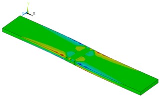
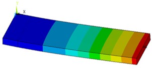
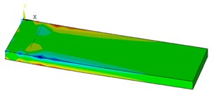
The outcomes of the experimental tests for the specimen (290D) reveal an excellent correlation with the results of the calibrated FE model with less than 5 % variance for the 1st and 2nd harmonic in all tests, while the double cantilever samples (500D) show the results by expressing 1-2 % variance for the 1st mode shape and with less than 10 % variance for the 2nd mode shape. The mode shapes of both the models for the 500D and 290D specimens can be seen in Fig. 6. In both cases, the first eigenmode is the first flapwise flexural vibration, while the second one is the first edgewise flexural vibration.
Fig. 6Frequency [Hz] vs. Damping Ratios [%] for all samples: a) 500D samples, b) 290D samples
![Frequency [Hz] vs. Damping Ratios [%] for all samples: a) 500D samples, b) 290D samples](https://static-01.extrica.com/articles/21812/21812-img10.jpg)
a)
![Frequency [Hz] vs. Damping Ratios [%] for all samples: a) 500D samples, b) 290D samples](https://static-01.extrica.com/articles/21812/21812-img11.jpg)
b)
Fig. 7Specimens mode shape built by ANSYS V. 19.1: a) 1st mode shape at 234.2 Hz (500D); b) 2nd mode shape at 922.2 Hz; c) 1st mode shape (290D); d) 2nd mode shape (290D)

a)
b)
c)
d)
Considering the damping ratio results, it seems the impact test outcomes have lower variation, in particular, for the 1st natural frequency. All tests depict a decay for the damping ratio by raising the frequencies. When analyzing the double-phase cores (i.e., presence of sand in the core), the white noise test did not resemble to show any differences between the specimens as the damping ratios are quite identical, especially for the 500D configuration [34].
This examination proved the damping ratio of hollow sphere specimens containing sand particles is slightly higher than the single-phase samples. The damping capacity of porous materials has been shown to improve by limiting the size of the macroscopic pores and increasing the volume fraction [38]. It confirmed that the silicate existence can improve the damping capacity of composite foams, as those particles make various interfaces [39], and composite foams show better damping and sound absorption due to the existence of particles with respect to the single-phase foams [7]. Filled metallic foams have up to five times higher damping capacity under a high level of vibration [31]. Besides, Gui et al. [40] have found the reinforced composite foams by Al/SiC have better damping capacity than hollow foams, while its impact on the dynamic characteristics is quite small.
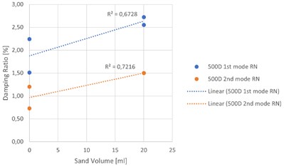
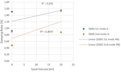
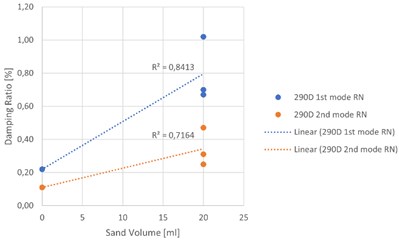
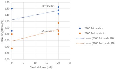
To conclude this work, Fig. 8 reports the experimentally defined relationships between the sand volume and the damping ratios (both for the first and the second mode). In both cases, one can see that by increasing the sand volume in both 500D and 290D specimens the damping ratios increases as well.
Fig. 8Experimental relationships between sand volume and damping ratio: a) random noise test, 500D specimens, b) hammer test, 500D specimens, c) random noise test, 290D specimens, d) hammer test, 290D specimens
a)
b)
c)
d)
5. Conclusions
An experimental examination of the dynamic properties of metallic foam structures (hollow sphere) has been reported here. The main aim was to determine their performance as passive dampers due to vibrations when disturbed by sand intrusions in their core. To meet this goal, two different experiments were applied to test and analyze the steel foams in a single-phase and double-phase (with quartz sand). Further, the identified Frequency Response Function both from the Random Noise and Impact Tests have been used to calibrate the Finite Element models of the specimens. Moreover, the damping ratios for both 290D and 500D individual samples have been computed, and for the 1st resonant frequency output, the ratios were found to increase for the samples which contain the sand particles. Comparatively, the damping ratio for the 1st natural frequency of the single-phase specimen is 1.55 % (sample 500D) and 1.73 % (sample 290D) sequentially, besides, for the two-phase sandwich core, the average damping ratio increased to 2.10 % (for the specimen 500D) and 1.17 % (for the specimen 290D). The damping ratios output of random noise results represents the fact that for the 1st mode of all specimens the damping ratios are higher than the solid steel samples (< 0.1 %). However, the 2nd frequencies output results have been shown varied responses that were particular for each test. The damping ratios for the 1st natural frequencies of all specimens were found to be more than three times of the results which are presented by Golleti et al. [33] as well as Banhart [41], where the specimens (aluminium foams) have been shaped with the similar conditions to our work, clamped in the middle (similar to 500D) and at the end (290D) respectively. This seems to highlight a major sensitivity of steel foams over aluminium foams to solid intrusions. Similarly, Yiatros et al. [18] have tested similar specimens (with comparable damping ratios for the single-phase steel foam cores) including lubricant oil with different volumes. The present study indicates that the damping ratios of sand-filled double-phase specimens are more than five times higher than the lubricant oil-filled ones. This indicates that sand intrusions can have much more marked effects under equal conditions. Furthermore, we believe that this investigation has a promising future looking to develop further results for using in FEM models by knowing the damping behaviour of the materials to predict the dynamic behaviour of the composite specimen and many questions are in this field remaining.
References
-
Patel P., Bhingloe P. P., Makwana D. Manufacturing, characterization and application of lightweight metallic foams for structural applications: review. Matreials Today: Proceedings, Vol. 5, 2018, p. 20391-20402.
-
Borsellino C., Calabrese L., Valenza A. Experimental and numerical evaluation of sandwich composite structures. Composites Science and Technology, Vol. 64, 2004, p. 1709-1715.
-
Lefebvre L. P., Banhart J., Dunand D. C. Porous metals and metallic foams: current status and recent developments. Advanced Engineering Materials, Vol. 10, 2008, p. 775-787.
-
Lamanna E., Gupta N., Cappa P., Strbik O. M., Kyu C. Evaluation of the dynamic properties of an aluminum syntactic foam core sandwich. Journal of Alloys and Compounds, Vol. 695, 2016, p. 2987-2994.
-
Ashby M. F., Evans A. G., Fleck N. A., Gibson L. J., Hutchinson J. W., Wadley H. N. G. Metal Foams: A Design Guide. Butterworth-Heinemann, USA, 2000.
-
Qiang Z., Yingfei L., Haitao C., Jing C., Gaohui W. Quasi-static and dynamic compression behavior of glass cenospheres. Composite Structures, Vol. 183, 2017, p. 499-509.
-
Jiejun W., Chenggong L., Dianbin W., Manchang G. Damping and sound absorption properties of particle reinforced Al matrix composite foams. Composites Science and Technology, Vol. 63, 2003, p. 569-574.
-
Sanders W. S., Gibson L. J. Mechanics of hollow sphere foams. Materials Science and Engineering, Vol. 347, 2002, p. 70-85.
-
Davies G. J., Zhen S. Metallic foams: their production, properties and applications. Journal of Material Science, Vol. 18, 1983, p. 1899-1911.
-
Lim T.-J., Smith B., Mcdowell D. L. Behavior of random hollow sphere metal foam. Acta Materialia, Vol. 50, 2002, p. 2867-2879.
-
Yu J. L., Li J. R., Hu S. S. Strain-rate effect and micro-structural optimization of cellular metals. Mechanics of Materials, Vol. 38, 2005, p. 160-170.
-
Garcia-Moreno F. Commercial applications of metal foams: their properties and production. Materials, Vol. 9, Issue 2, 2016, p. 85.
-
Jing L., Yang F., Zhao L. Perforation resistance of sandwich panels with layered gradient metallic foam cores. Composite Structures, Vol. 171, 2017, p. 217-226.
-
Banhart J. Manufacture, characterisation and application of cellular metals and metal foams. Progress in Materials Science, Vol. 46, 2001, p. 559-632.
-
Katunin A. Vibration-based spatial damage identification in honeycomb-core sandwich composite structures using wavelet analysis. Composite Structures, Vol. 118, 2014, p. 385-391.
-
Mishnaevsky L., Branner K., Petersen H. N., Beauson J., McGugan M., Sørensen B. F. Materials for wind turbine blades: an overview. Materials, Vol. 10, 2017, p. 1285.
-
Xie Z., Yan Q., Li X. Investigation on low velocity impact on a foam core composite sandwich panel. Steel and Composite Structures, Vol. 17, 2014, p. 159-172.
-
Yiatros S., Petrunin I., Zanotti L., Brennan F. P. Experimental Investigation of Vibration Damping in Steel Foam Sandwich Structure. Cranfield University, UK, 2017.
-
Civera M., Zanotti Fragonara L., Surace C. A novel approach to damage localisation based on bispectral analysis and neural network, Smart Structures and Systems, Vol. 20, Issue 6, 2017, p. 669-682.
-
Civera M., Ferraris M., Ceravolo R., Surace C., Betti R. The teager-kaiser energy cepstral coefficients as an effective structural health monitoring tool. Applied Sciences, Vol. 9, Issue 23, 2019, p. 5064.
-
Civera M., Zanotti Fragonara L., Surace C. An experimental study of the feasibility of phase‐based video magnification for damage detection and localisation in operational deflection shapes. Strain, Vol. 56, Issue 1, 2020, p. e12336.
-
Martucci D., Civera M., Surace C. The extreme function theory for damage detection: an application to civil and aerospace structures. Applied sciences, Vol. 11, 2021, p. 1716.
-
Muriel J., Sanchez R. A., Barona M. W., Sanchez S. H. Steel and gray iron foam by powder metallurgical synthesis. Suplemento de la Revista Latinoamericana de Metalurgia y Materiales, Vol. 4, 2009, p. 1435-1440.
-
Rizov V., Shipsha A., Zenkert D. Indentation study of foam core sandwich composite panels. Composite Structures, Vol. 69, 2005, p. 95-102.
-
Arwade S. R., Hajjar J. F., Schafer B. W., Moradi M., Smith B. H., Szyniszewski S. Steel foam material processing, properties, and potential structural applications. NSF Engineering Research and Innovation Conference, Atlanta, Georgia, 2011.
-
Smith B. H., Szyniszewski S., Hajjar J. F., Schafer B. W., Arwade S. R. Steel foam for structures: A review of applications, manufacturing and material properties. Constructional Steel Research, Vol. 71, 2011, p. 1-10.
-
Treviso A., Genechten Van B., Mundo D., Tournour M. Damping in composite materials: properties and models. Composites Part B, Vol. 78, 2015, p. 144-152.
-
Ramamurty U., Paul A. Variability in mechanical properties of a metal foam. Acta Material, Vol. 52, 2004, p. 869-876.
-
Jing L., Wang Z., Ning J., Zhao L. The dynamic response of sandwich beams with open-cell metal foam cores. Composites Part B: Engineering, Vol. 42, 2011, p. 1-10.
-
Vaidya U., Pillay S., Bartus S., Ulven C., Grow D., Mathew B. Impact and post-impact vibration response of protective metal foam composite sandwich plates. Materials Science and Engineering: A, Vol. 428, 2006, p. 59-66.
-
Tu Y., Wang G. Damping parameter identification and study of metal foam filled steel tube. Journal of Materials in Civil Engineering, Vol. 22, Issue 4, 2010, p. 397-402.
-
Min C. H., Hong S., Park S. Y., Park D. C. Sensitivity- based finite element model updating with natural frequencies and zero frequencies for damped beam structures. International Journal of Naval Architecture and Ocean Engineering, Vol. 6, 2014, p. 904-921.
-
Goletti M., Mussi V., Rossi A., Monnob M. Procedures for damping properties determination in metal foams to improve FEM modeling. Procedia Materials Science, Vol. 4, 2014, p. 233-238.
-
Farhadi S., Ziadloo S. Dynamic characterization and modeling of steel foam sandwich structure. Vibroengineering Procedia, Vol. 27, 2019, p. 145-149.
-
Boscato G., Russo S., Ceravolo R., Fragonara L. Z. Global sensitivity‐based model updating for heritage structures. Computer‐Aided Civil and Infrastructure Engineering, Vol. 30, Issue 8, 2015, p. 620-635.
-
Zanotti Fragonara L., Boscato G., Ceravolo R., Russo S., Ientile S., Pecorelli M. L., Quattrone A. Dynamic investigation on the Mirandola bell tower in post-earthquake scenarios. Bulletin of Earthquake Engineering, Vol. 15, Issue 1, 2017, p. 313-337.
-
Civera M., Zanotti Fragonara L., Surace C. A computer vision-based approach for non-contact modal analysis and finite element model updating. Proceedings of EWSHM 2020.
-
Wei J. N., Li Z. B., Han F. S. Damping Behavior and Mechanism of Foamed Zn-Al Eutectoid Alloy. Physica Status Solidi, Vol. 191, Issue 2, 2002, p. 435-444.
-
Sirong Y., Jiaan L., Yanru L., Yaohui L. Compressive behavior and damping property of ZA22/SiCp composite foams. Materials Science and Engineering: A, Vol. 457, 2007, p. 325-328.
-
Gui M. C., Wang D. B., Wu J. J., Yuan G. J., Li C. G. Deformation and damping behaviors of foamed Al – Si – SiCp composite. Materials Science and Engineering: A, Vol. 286, 2000, p. 282-288.
-
Banhart J. Damping properties of aluminum foams. Materials Science and Engineering: A, Vol. 205, 1996, p. 221-228.
About this article
The authors give thanks to Prof. Cecilia Surace from Politecnico di Torino for allowing his period abroad at Cranfield University and Dr. Luca Zanotti Fragonara for his help with the experimental set-up and advice.
