Abstract
Fuel injection nozzle is one of the key components of fuel injection system. The accuracy of the temperature field analysis is related to its working reliability. In order to obtain the temperature field of the nozzle, this paper considers the interaction of the fluid domain and solid domain, establishing a heat transfer model by fluid-solid coupling method. Compared with empirical formula method, the results show that the coupling method can fully simulate the characteristics of the flow fluid and improve precision of the temperature of the nozzle, which plays an important role in the subsequent thermal fatigue analysis of the nozzle.
Highlights
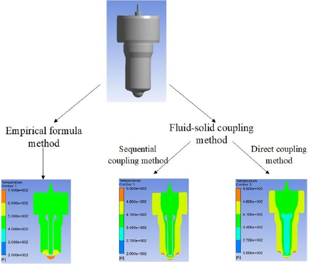
- The simulation results of the nozzle are compared with empirical formula method and fluid-solid coupling method.
- Fluid-solid coupling method can fully simulate fluid characteristics and fit the actual conditions well.
- Sequential coupling method is a priority when solid deformation is negligible.
1. Introduction
Fuel injection nozzle plays an important role in communicating the injection system and the combustion system. When it is working, the fuel oil is injected from the pressure chamber, which mixed with air to form combustible gas. When the gas is burning, the heat generated is transferred to the nozzle, resulting in its excessive temperature [1]. In order to ensure its service life, it is necessary to carry out an accurate temperature field analysis to reduce its heat load.
Many researchers have carried out relevant temperature analysis on the nozzle. Through the engine bench test, Shizhen Li simulated actual operation condition of the nozzle, and obtained the limit temperature of the nozzle. Lin Wang introduced the calculation method of convective heat transfer coefficient in different areas of the nozzle chamber, and obtained its temperature distribution. And some researchers proposed empirical formulas to calculate transfer heat coefficient of the fluid to obtain boundary conditions of the nozzle [2-4]. However, empirical formula method cannot accurately acquire the fluid state to reflect its actual condition.
Therefore, this paper introduces the fluid-solid coupling method and uses finite element software ANSYS to get its actual temperature field. Compared with the results obtained by empirical formula method, the fluid-solid coupling method has a significant advantage by simulating the fluid characteristics and acquiring accurate temperature field.
2. Theoretical basis of fluid-solid coupling
The fluid-solid coupling theory can be divided into sequential coupling method and direct coupling method according to the coupled physical field. The sequential coupling method is to arrange multiple physics fields in a certain order for analysis, and each analysis involves a single field. The direct coupling method is to couple multiple fields through the element matrix and only perform a numerical simulation once [5].
2.1. The governing equation of fluid
All flow fluid obeys three basic laws: the continuity equation, the conservation of momentum and the conservation of energy. For incompressible fluid, the continuity equation is:
The conservation of momentum of incompressible fluid can be expressed by:
where, p represents the pressure, f is the unit mass force and μ is the fluid viscosity.
And the conservation of energy is:
where, λ is the thermal conductivity, htot is the total enthalpy, and SE is the energy source.
2.2. The governing equation of solid
The governing equation for the displacement of solid caused by the fluid is:
In the equation, Ms is the mass matrix, Cs is the damping matrix, Ks is the stiffness matrix, r is the displacement, and τs is the stress.
2.3. Heat transfer equation
Heat transfer equation of convection is expressed by:
where, is the convective heat transfer coefficient, is the heat flux density and is temperature differential.
2.4. Coupling control equation
In coupling interface between the fluid domain and solid domain, the displacement, heat flow, temperature and stress of the fluid domain and the solid domain should be equal:
where, is the displacement, is the heat flow, is the temperature, and is the stress.
3. Model and numerical simulation
3.1. Physical geometry and mesh
The fuel injection nozzle is assembled by two parts. One part is the needle valve, and its conical surface plays a role of blocking fuel. The other part is the needle valve body. When it is in use, the fuel oil is injected from the nozzle hole. The physical geometry of the nozzle is imported into ANSYS, as shown in Fig. 1. And the fluid domain is extracted by the fill function.
Then mesh the solid domain and the fluid domain, the generated mesh is shown in Fig. 2. In the solid field, the number of elements is 995015 and the number of nodes is 184400. In the fluid domain, the number of elements is 663979 and the number of nodes is 261980.
Fig. 1Geometry of the nozzle
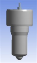
Fig. 2Mathematical model of the nozzle

3.2. Material definition
In the thermal analysis, some material properties are needed such as the specific heat, the viscosity and the thermal conductivity of the fluid, shown in Table 1. The thermal conductivity of the nozzle is also involved, shown in Table 2.
Table 1Detailed material properties of the fluid
Part name | Thermal conductivity (W/(m·K)) | Density (kg/m3) | Viscosity (Pa·s) | Specific heat (J/(kg·K)) |
Fuel oil | 0.149 | 730 | 0.0024 | 0.3 |
Table 2Detailed material properties of the solid
Part name | Thermal conductivity (W/(m·K)) | Density (kg/m3) | Poisson’s ratio | Elastic strength (MPa) |
Needle valve | 16.27 | 8030 | 0.3 | 2.07E5 |
Needle body | 16.27 | 8030 | 0.3 | 2.07E5 |
3.3. Boundary conditions
According to the heat transfer characteristics in different positions of the fuel injection nozzle, the boundary region can be divided into three parts: the nozzle head, the upper middle of the nozzle and the internal nozzle passage.
3.3.1. Boundary settings of the head of the nozzle
The nozzle head extends into the combustion chamber during installation. When the gas is burning, its surface is in direct contact with the high-temperature gas. Therefore, the heat transfer process is convective heat transfer.
Although the temperature and heat transfer coefficient of the gas are dynamically changing in a cycle, temperature fluctuations only occur in a very thin layer on the surface, the amplitude is small and decays rapidly. Therefore, it can be considered that the heat transfer process is steady. Through several experiments, Xiaoli Yu obtained a series of empirical formulas of the gas [6, 7]. The average heat transfer coefficient and average temperature of the gas can be calculated by the following equations:
where, is the average heat transfer coefficient, is the average temperature, is a cycle time.
3.3.2. Boundary setting of the upper middle of the nozzle
The middle and upper part of the fuel injection nozzle is embedded in the cylinder head. Because the gap between the two is too small, this area can be considered to transfer heat through conduction. Therefore, the heat transfer mode is the heat conduction and the boundary condition can be obtained by measuring the cylinder head temperature.
3.3.3. Boundary conditions of the internal nozzle passage
When the fuel injection nozzle is working, the fuel oil is injected from the nozzle hole to take away part of the heat. Therefore, the heat transfer process is convection. Obviously, the heat transfer coefficient here mainly depends on the fluid flow state, which can be given by empirical formula or the fluid-solid coupling simulation.
The empirical formula method is to consider the heat transfer coefficient of the fluid was constant. The temperature can be obtained by measuring the inner wall of the nozzle, and the heat transfer coefficient can be calculated with the Dittus-Boelter formula [7]:
As the oil flows, the heat transfer coefficient is constantly changing with the flow position. Except the empirical method, this paper uses fluid-solid coupling method to obtain accurate fluid characteristics. Then the flow fluid parameters are automatically applied by the analysis module to the solid domain to obtain accurate temperature field of the fuel injection nozzle.
4. Results
4.1. Simulation result based on empirical formula method
The heat transfer coefficient of the fuel oil is 3422.23 W/(m2·K) according to empirical formula, and the wall temperature is 456 K. With this boundary conditions, the temperature field of the fuel nozzle can be analyzed through the software ANSYS. In order to avoid the influence of elements, independence verification is required. Refine the elements until the difference between two results is within 5 %, the result is considered credible. The verification results are shown in Table 3. Similarly, the fluid-solid coupling simulation is also verified.
Table 3Maximum temperature under different elements
Elements | 41537 | 432842 | 1407248 | 41537 |
Temperature / K | 689.24 | 689.77 | 689.78 | 689.24 |
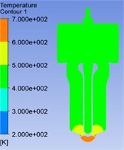
It can be seen from Fig. 3 that due to the special structure of the nozzle and different heat transfer conditions, the temperature field is unevenly distributed. The temperature of the nozzle head changes sharply and its gradient is much larger than other areas. The temperature increases gradually from top to bottom and the highest temperature occurs at the head of the nozzle, the value of which is 689.8 K. This is because this part is directly affected by the high-temperature gas. In the area above the needle valve seat, the temperature is lower and the distribution is relatively uniform because of the influence of convective heat transfer of the oil.
Fig. 3Temperature cloud chart of the nozzle
4.2. Simulation results based on fluid-structure coupling method
In this paper, sequential coupling method and direct coupling method are used to analyze the temperature field of the fuel injection nozzle and the results of the two simulation are compared.
4.2.1. Results of sequential coupling method
When using sequential coupling, the fluid domain and the solid domain are respectively simulated. The CFD method is first used to obtain the fluid characteristics, then transfer the heat transfer coefficient and temperature to the nozzle passage through the coupling interface.
The mathematical result is shown in Fig. 4. It can be seen that the temperature field is not even too and the temperature of the nozzle head changes very sharply. The highest temperature 513.6 K occurs at the nozzle tip because of the high-temperature gas. And the temperature and its gradient gradually decrease from the head upwards.
Compared with the results obtained based on empirical formula method, the maximum temperature all appears at the nozzle head, but the difference between two values is 176 K. This is because in the actual flow of the fluid, the heat transfer coefficient in the nozzle head reaches tens of thousands. Therefore, the oil can take more heat than the empirical formula method and the maximum temperature decreases. Due to the heat transfer coefficient near the nozzle hole is the biggest, it has a greater temperature drop than other region of the head. Therefore, the temperature field of the nozzle head is also uneven. The temperature is the lowest near the nozzle hole and gradually increases from the hole to the sides.
4.2.2. Results based on direct coupling method
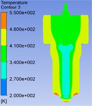
The direct coupling method is to place the two physical fields in the same analysis module, which makes the heat transfer model better fit the actual working condition. The result is shown in Fig. 5. The maximum temperature appears at the nozzle head, which value is 512.6 K and the temperature increases gradually from top to bottom. Besides, near the nozzle hole is the lowest temperature and the temperature gradually increases from the nozzle hole to the sides.
It can be seen that the two coupling method simulation results are consistent. This is because the deformation of solid caused by fluid is negligible. Since the two physics fields are analyzed separately in sequential coupling method, the computing space occupied is smaller and the computing speed is faster. Therefore, priority is given to the sequential coupling method when analyzing the fluid-solid thermal coupling model if the solid deformation is too small.
Fig. 4Temperature cloud chart of the nozzle
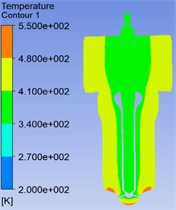
Fig. 5Temperature cloud chart of the nozzle
5. Conclusions
In this paper, ANSYS is used to simulate the fluid-solid thermal coupling model of the fuel injection nozzle with fluent to acquire the temperature field. Compared with the results acquired by the empirical formula method, the following conclusions are obtained:
1) Using the empirical formula to obtain the heat transfer coefficient of the fluid as the boundary conditions, the temperature simulated is higher and the result is conservative.
2) With the fluid-solid coupling method, it can fully simulate fluid characteristics and the temperature obtained fit the actual conditions well.
3) Results obtained by sequential coupling and direct coupling are consistent. But when solid deformation is too small, sequential coupling method is better for its less computing space.
4) This temperature analysis plays an important role in subsequent thermal fatigue of the nozzle, and has a guiding significance to other similar fluid-solid couple models.
References
-
Liu Yanhui Analysis and elimination of common troubles in diesel engine injector. Diesel Engine, Vol. 33, Issue 1, 2011, p. 54-56.
-
Li Shizhen, Xue Lei Analysis of nozzle peak temperature and design of bench testing program. I.C.E. & Power Plant, Vol. 4, 2012.
-
Wang Lin, Cheng Rongxin Analysis of temperature field in nozzle chamber of steam turbine. Turbine Technology, Vol. 57, Issue 2, 2015, p. 96-99.
-
Ci Ying Fundamentals of Fluid and Heat Transfer. First edition, Science Press, Beijing, 2016.
-
Yang Fuqin, Liu Xin Fluid-solid coupling characteristics analysis for tripod sliding universal joints. Mechanics and Industry, Vol. 20, Issue 2, 2019, p. 201.
-
Yuan Jiangtao, Ouyang Guangyao Three-dimensional finite element thermal analysis of diesel fuel injector. Vehicle Engine, Vol. 1, 2005, p. 64-67.
-
Chen Yutao, Wang Zuoqun Simulation analysis of temperature field of common rail injector based on multi-field coupling. Journal of System Simulation, Vol. 37, Issue 7, 2019, p. 1334-1341, (in Chinese).
Cited by
About this article
The authors gratefully acknowledge the support from the National Natural Science Foundation of China (Grant No. 51574161).
