Abstract
Abrasive flow machining technology has unique advantages in improving the surface quality of precision parts. In order to study the effect of abrasive flow machining on the curved inner surface workpieces used in special environments, the U-tube was used as the research object, and the large eddy simulation (LES) method was used to numerically simulate the abrasive flow polishing U-tube process. The turbulence kinetic energy cloud diagram, wall shear stress cloud diagram and fluid trajectory diagram of the abrasive flow composed of solid-phase silicon carbide and liquid-phase oil at different inlet speeds on the inner surface of the U-tube were drawn, and the situation of abrasive flow and vortex formation in the process of abrasive flow machining were obtained. The influence of different inlet speeds on the quality of abrasive flow polishing U-tube was analyzed, which provided theoretical support for future research work.
Highlights
- The large eddy simulation method is used to study the abrasive flow polishing U-shaped tube.
- The influence of changes in inlet speeds on turbulence kinetic energy and wall shear stress is investigated.
- The abrasive flow and vortex formation are analyzed through different fluid trajectories.
1. Introduction
Curved tube parts are widely used in daily life and industrial production. With the development of society, the requirements for the surface quality of such parts are higher and higher. The internal structure of curved tube parts is relatively complex, and the traditional polishing technology cannot effectively polish the internal surface, and abrasive flow polishing technology emerges as the times require. Abrasive flow polishing technology can be used to process parts with a complex inner cavity, which is suitable for some curved tube parts with small diameter, and the polished surface can be uniform and complete [1, 2]. Therefore, it is of great engineering value to study the abrasive flow polishing of the inner surface of the curved tube. Kheradmand et al numerically simulated the processing process of the magnetorheological medium through the axially rotating pipe under the action of an external magnetic field. It was concluded that the magnetic field strength increased from 0 to 0.2T can improve the surface roughness up to 60 % [3]. Butola R. et al summarized the study of the parameters (Number of process cycles, Extrusion pressure and Abrasive concentration) and experimented variation used in Abrasive flow machining (AFM) for the surface finishing process and its optimization using Taguchi method. It had been found through the experiment that the optimum result was obtained when ‘Number of cycles is equal to 6, Extrusion pressure is 15 bars and Abrasive concentration is 100 gm’, which showed that the percentage difference in surface roughness after machining was 26.42 % [4]. Wang et al proposed a new AFM for surface finishing, which does not require any special devices except for a tool bar. It was concluded that the optimum abrasive grain size utilized in the new AFM is related to the standoff distance between tool bar and workpiece during finishing process [5]. Li et al used the large eddy simulation method to study the surface formation mechanism of solid-liquid two-phase abrasive flow processing, discussed the trajectory of abrasive flow composed of solid-phase silicon carbide and liquid-phase hydraulic oil on the inner surface of elbow, and studied the distribution characteristics of solid-liquid two-phase abrasive flow pattern. Besides, the wear and erosion of the abrasive particles and the wall surface of the workpiece were discussed [6].
2. The method of large eddy simulation
The turbulence contains a series of large and small vortex clusters, and the scale of the vortex is quite wide. The LES method is based on solving the N-S equation of the model directly when the mesh of the model is not closed [7]. It requires a larger grid size than the general turbulent size, so the large eddy simulation method has a good effect on the turbulent flow process. The reason for the turbulent pulsation phenomenon and the mixing phenomenon is the flow of large eddies, and the large vortex has a relatively strong non-isotropy and changes with the process of fluid flow. There are interaction forces between the large vortices, which can transfer the energy in the flow process to the small vortices. Then, the small vortices can slowly consume the energy obtained, and the small vortices are isotropic.
In the LES method, a filter function is first constructed to divide the transient variables of the fluid into large-scale average components and small-scale components, and the Navier-Stokes equation is filtered to obtain the following Eqs. (1) and (2):
where is the velocity of the fluid, is the time, is the density of the fluid, is pressure, is viscosity coefficient, is the subgrid stress, and , and represent space coordinates , and , respectively.
In Eq. (1), . Since and cannot be obtained simultaneously, a closed mode of subgrid stress must be constructed. The most commonly used model is the assumption of the concept of eddy viscosity, that is:
where is subgrid eddy viscosity coefficient, and 1/2, is transition scale, is equivalent to the mixing length, is Smagorinsky constant. The simple subgrid stress model is called the Smagorinsky model.
3. Numerical simulation model construction and analysis
3.1. Modeling and meshing of U-tube workpiece
In some precision machinery, U-tube is used for pipe connection. To complete the research on the large eddy numerical simulation of the abrasive flow polishing U-tube, the first step is to establish the U-tube model. The model and size of U-tube are shown in Fig. 1.
In order to analyze the distribution of abrasive particle flow at different positions of the U-tube more accurately, two different regions of inlet and outlet are defined for the U-tube. The cross-section to be studied is determined and the mesh is divided. The divisions are shown in Fig. 2.
The quality of the mesh has a great influence on the subsequent calculation. When the mesh is too rough, it will lead to the instability of the calculation process, resulting in a large error in the calculation results. Therefore, the mesh generation should be as neat and detailed as possible. After meshing, the mesh quality is checked. The area and volume of the mesh are not negative, so the mesh quality of U-tube is qualified.
Fig. 1The model of U-bend
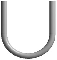
a) Three-dimensional model of U-bend
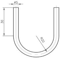
b) Dimension diagram of U-tube
Fig. 2Region division and meshing of U-tube
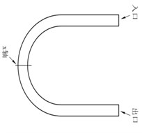
a) Region division of U-tube
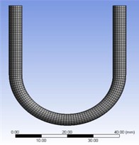
b) Meshing of U-tube
3.2. Parameter settings and boundary conditions
In this paper, solid-liquid two-phase abrasive flow polishing U-tube is simulated. The abrasive flow fluid is incompressible, and the three-dimensional double precision solver based on pressure is selected for analysis. The solid phase of abrasive flow is SiC particles with a density of 3170 kg/m3, and the liquid phase is oil with a density of 1260 kg/m3. For the solid-liquid two-phase polishing liquid, the Mixture model is selected, and the LES is used for numerical simulation analysis. According to the Reynolds number calculation formula , it can be seen that when the flow speed of the abrasive particle is greater than 20 m/s, the turbulent flow conditions can be met. So the speeds of this large eddy simulation are selected as 30 m/s, 40 m/s, 50 m/s and 60 m/s to study abrasive flow polishing characteristics.
The solid-liquid two-phase polishing fluid used in this paper is incompressible, and the speed-inlet boundary condition is generally used to solve the flow phenomenon of an incompressible fluid, so the speed-inlet boundary condition is adopted. It is difficult to measure the speed and pressure of polishing fluid at the outlet, so the free-outlet boundary condition is selected.
3.3. Numerical simulation analysis of abrasive flow polishing U-tube under different speed conditions
Under the condition of abrasive volume fraction of 30 %, different inlet speed conditions are set to 30, 40, 50 and 60 m/s. The turbulence kinetic energy cloud diagram, wall shear stress cloud diagram and fluid trajectory diagram of solid-liquid two-phase abrasive flow polishing U-tube are obtained by the LES method.
3.3.1. Effect of turbulent kinetic energy on abrasive flow polishing characteristics at different inlet speeds
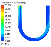
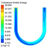
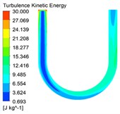
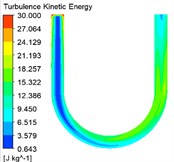
The turbulent kinetic energy has a great influence on the characteristics of abrasive flow polishing. The turbulent kinetic energy distribution cloud diagrams under different inlet speed conditions are shown in Fig. 3.
Fig. 3Turbulent kinetic energy cloud diagrams under different inlet speed conditions
a)30 m/s
b)40 m/s
c)50 m/s
d)60 m/s
It can be seen from the turbulent kinetic energy cloud diagrams shown in Fig. 3 that the abrasive has larger turbulent kinetic energy at the entrance of the U-tube than the turbulent kinetic energy at the straight pipe of the inlet. As the abrasive continues to flow, the turbulent kinetic energy gradually increases. The turbulent kinetic energy is larger at the curved pipe and the straight pipe of the outlet, where the polishing effect is better. Finally, the turbulent kinetic energy near the outlet decreases gradually. When the inlet velocity increases from 30 m/s to 60 m/s, the color in the cloud chart changes, and the value represented shows an increasing trend. Therefore, the turbulent kinetic energy in the U-tube increases with the increase of inlet speed, and the movement of abrasive particles in the pipe is more irregular. So the abrasive scouring the pipe wall is more serious, and the polishing effect of abrasive flow is better.
3.3.2. Effect of wall shear stress on abrasive flow polishing characteristics at different inlet speeds
The wall shear stress also has a great influence on the characteristics of abrasive flow polishing U-tube. The wall shear stress distribution cloud diagrams under different inlet speed conditions are shown in Fig. 4.
Fig. 4The wall shear stress cloud diagrams under different inlet speed conditions
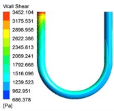
a)30 m/s
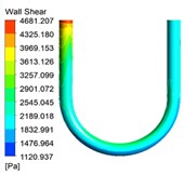
b)40 m/s
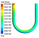
c)50 m/s
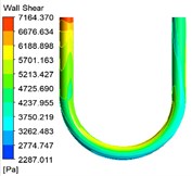
d)60 m/s
It can be seen from the turbulent kinetic energy cloud diagrams shown in Fig. 3 that the wall shear stress is the largest at the entrance of U-tube, where the polishing effect is the best. As the abrasive continues to flow, the wall shear stress gradually decreases. Then it will increase at the curved pipe, and decrease again at the straight pipe at the outlet. Due to the influence of the pipe structure, the wall shear stress of the curved pipe is larger, and the wall shear stress on the inner side of the bending section is greater than the wall shear stress on the outer side, so the polishing effect on the inner side is better. As the inlet speed increases, the overall wall shear stress increases, and the polishing effect on the wall surface of the workpiece is better. At the same time, too much wall shear force will cause damage to the workpiece. So in the actual processing, we should select the appropriate parameters according to various factors.
3.3.3. Fluid trajectory analysis at different inlet speeds
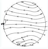
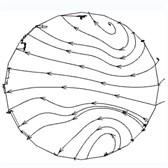
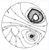
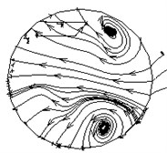
In order to analyze the influence of the inlet speed on the abrasive flow polishing U-tube, the speeds of 30 m/s, 40 m/s, 50 m/s and 60 m/s are used to obtain the trajectory of the fluid, and the trajectory diagram is analyzed. Among them, the U-tube bottom circular section is -axis. The trajectory diagrams in the -axis direction are shown in Fig. 5.
Fig. 5The trajectory diagrams in the x-axis direction at different inlet speeds
a)30 m/s
b)40 m/s
c)50 m/s
d)60 m/s
It can be seen from the trajectory diagrams in the -axis direction at different inlet speeds in Fig. 5 that the distribution of the -axis vortex gradually changes from a straight line to a spiral. This phenomenon does not change much when the speed is 30 m/s to 40 m/s. The change is particularly obvious from 40 m/s to 50 m/s, and there are obvious vortices in the upper right corner and the lower right corner at 50 m/s and 60 m/s. It can be seen from Fig. 5 that with the increase of inlet speeds, the flow of the abrasive changes from the same flow to the random flow in different directions, which is conducive to the formation of the vortex and improves the polishing effect.
4. Conclusions
The turbulence kinetic energy cloud diagram, wall shear stress cloud diagram and fluid trajectory diagram of solid-liquid two-phase abrasive flow polishing U-tube with inlet speeds of 30 m/s, 40 m/s, 50 m/s and 60 m/s are studied by LES method. The major conclusions obtained from this work are as follows:
1) The turbulent flow energy and wall shear stress are the largest at the entrance of the U-tube, where the polishing effect is the best. As the abrasive flows in the workpiece, the turbulence energy and wall shear stress decrease at the straight pipe of the inlet. Furthermore, it increases at the curved pipe and decreases at the straight pipe at the outlet. At the curved pipe, the turbulent flow energy and wall shear stress of the inner wall are greater than those of the outer wall. Therefore, the processing effect of the solid-liquid two-phase abrasive flow polishing U-tube at the curved pipe is better than the processing effect of the straight pipe at both ends, and the processing effect of the inner wall of the curved pipe is better than the outer wall. At the same time, with the increase of inlet speed, the turbulence energy and wall shear stress increase, and the polishing effect of the workpiece wall becomes better.
2) It can be seen from the trajectory diagram that with the increase of inlet speed, the flow direction of the polishing fluid on the -axis section becomes more random. The randomness makes the more abrasives enter into the vortex, which is beneficial to the formation of the fluid vortex and can promote the polishing of the workpiece wall by the polishing fluid.
References
-
Sambharia J., Mali S. Recent developments in abrasive flow finishing process: A review of current research and future prospects. Proceedings of the Institution of Mechanical Engineers Part B Journal of Engineering Manufacture, Vol. 3, Issue 1, 2017, p. 42-53.
-
Petare C., Jain K. A critical review of past research and advances in abrasive flow finishing process. The International Journal of Advanced Manufacturing Technology, Vol. 97, Issues 1-4, 2018, p. 741-782.
-
Kheradmand S., Esmailian M., Fatahy A. Numerical simulation of the combination effect of external magnetic field and rotating workpiece on abrasive flow finishing. Journal of Mechanical Science and Technology, Vol. 31, Issue 4, 2017, p. 1835-1841.
-
Butola R., Jain R., Bhangadia P., et al. Optimization to the parameters of abrasive flow machining by Taguchi method. Materials Today Proceedings, Vol. 5, Issue 2, 2018, p. 4720-4729.
-
Wang Tingting, Chen De, Zhang Weihua, et al. Study on key parameters of a new abrasive flow machining (AFM) process for surface finishing. The International Journal of Advanced Manufacturing Technology, Vol. 101, Issues 1-4, 2018, p. 39-54.
-
Li Junye, Su Ningning, Wei Lili, et al. Study on the surface forming mechanism of the solid-liquid two-phase grinding fluid polishing pipe based on large eddy simulation. Proceedings of the Institution of Mechanical Engineers Part B Journal of Engineering Manufacture, Vol. 233, Issue 14, 2019, p. 2505-2514.
-
Li Junye, Zhang Hengfu, Wei Lili, et al. Formation mechanism and quality control technology for abrasive flow precision polishing vortex: large eddy simulation. The International Journal of Advanced Manufacturing Technology, Vol. 105, Issues 5-8, 2019, p. 2135-2150.
About this article
The authors would like to thank the National Natural Science Foundation of China No. NSFC 51206011 and U1937201, Jilin Province Science and Technology Development Program of Jilin Province No. 20200301040RQ, Project of Education Department of Jilin Province No. JJKH20190541KJ, Changchun Science and Technology Program of Changchun City No. 18DY017.

