Abstract
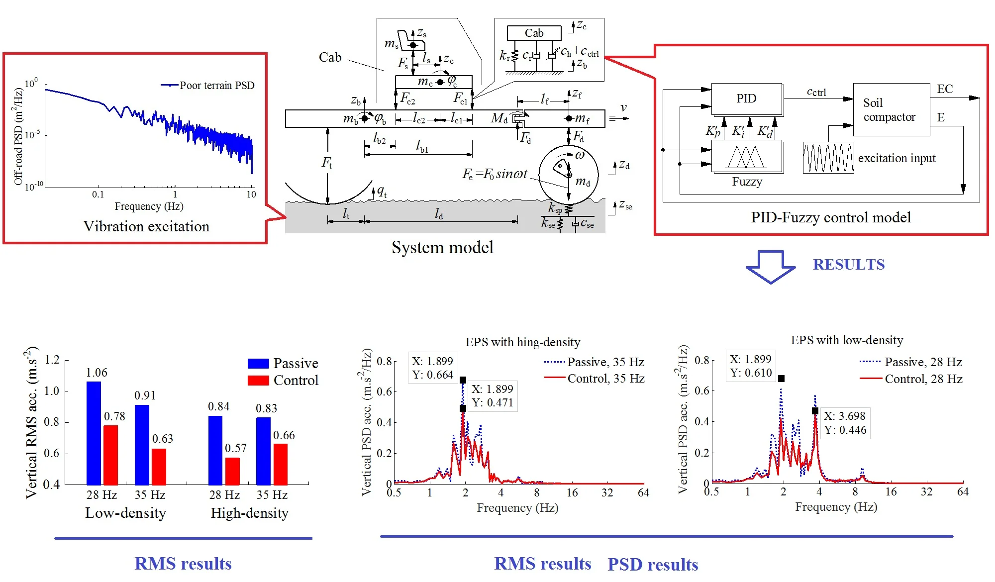
To improve the soil compactor ride comfort, a combined control method of Fuzzy and PID control is proposed to control the cab isolation system of soil compactor based on the non-linear vehicle dynamic model. The vibration excitation sources are concerned by the vibrator drum and elastoplastic soil (EPS) interactions in the compression process. The power-spectral-density (PSD) and weighted root-mean-square (RMS) of acceleration responses of both the vertical driver’s seat and pitching cab angle are chosen as the objective functions. The research results show that both the PSD and weighted RMS values of the vertical driver’s seat and pitching cab angle are significantly reduced by using the PID-Fuzzy control under various EPSs in the low-frequency region, especially on the EPS with high-density.
Highlights
- A combined control method of Fuzzy and PID control has successfully developed to control the cab isolation system of soil compactor.
- The power-spectral-density (PSD) of the vertical driver’s seat and pitching cab angle is remarkably improved under various compaction conditions of the soil compactor, especially under a low-frequency.
- The weighted root-mean-square (RMS) of acceleration responses of both the vertical driver’s seat and pitching cab angle is greatly reduced, thus, the driver’s ride comfort and health is significantly improved.
- The PID-Fuzzy control not only improves the ride comfort of the soil compactor but also controls the cab shaking under various working conditions.
- The research results also show that the PID-Fuzzy control is not only effective for vehicles moving on the rigid roads, but also effective for vehicles moving on off-road roads.
1. Introduction
The soil compactor performance was evaluated not only by the compression efficiency of the vibratory drum on the soil, asphalt and other materials but also by the driver’s ride comfort [1, 2]. Therefore, in order to achieve the maximum excitation force of the vibrator drum, the drum-elastoplastic soil (EPS) interaction models were studied and analyzed [3, 4], the research results showed that the compression performance of the soil compactor was maximum at the excitation frequency region from 15-40 Hz of the vibratory drum [5], especially at a low frequency 28.5 Hz and high frequency 33 Hz of the vibratory drum [1, 3]. However, these vibration excitations transmitted to the driver via the cab isolation system were very high, so the driver’s feel was very uncomfortable. To solve this issue, to improve the cab isolation system was one of the most important problems.
The cab isolation system of the soil compactor equipped with the rubber mounts was analyzed and evaluated on the driver’s ride comfort [1]. The design parameters were then optimized to improve the ride comfort [6]. However, the weighted RMS values of the driver and cab were high under various working conditions, especially the cab shaking. Three cab isolation systems including rubber, hydraulic, and pneumatic mounts to increase the ride comfort were proposed [2]. The research results showed that the driver’s rider comfort and the cab shaking were significantly reduced by the cab isolation system used the hydraulic mounts in the low-frequency region. However, the vibrations of the vertical driver’s seat and cab pitch angle are still great in the moving condition of the vehicle according to the ISO 3615-1 [7]. Therefore, to reduce the vibration of the driver’s seat and cab, the cab hydraulic mount should be controlled.
The hydraulic mounts applied for engine isolation mount [8] were controlled to decrease the engine vibrations [9]. Besides, some construction vehicles cab using the hydraulic mounts [10, 11] were optimized and controlled to improve the ride comfort. However, the researches only concerned under the vibration excitations of the rigid road surface roughness. Nowadays, the combined control methods such as PID-Fuzzy [12, 13], Hinf-Fuzzy, or Skyhook-NFLC control [14, 15]were applied to control the damping forces for the semi-active suspension system or active suspension system of vehicles and seat. The results showed that the ride comfort was significantly increased by using the above control methods. Therefore, this paper, based the combined control method of the PID-Fuzzy, the cab isolation system equipped with the hydraulic mounts is controlled via the non-linear dynamic model of the soil compactor to improve the ride comfort. The performance of the cab hydraulic mounts with the PID-Fuzzy control is then evaluated via the power-special-density (PSD) and weighted root-mean-square (RMS) of acceleration responses of both the vertical driver’s seat and pitching cab angle under the various compression conditions of the drum-EPS interactions and in the low-frequency region of the soil compactor.
2. Materials and methods
2.1. Dynamic model and motion equations
Based on the actual structure of the soil compactor, a nonlinear dynamic model of a single drum vibratory roller with 7DOF is built to evaluate the control performance of the PID-Fuzzy control for cab isolation system equipped with the hydraulic mount (HM) [2, 6, 11], as plotted in Fig. 1.
Fig. 1Dynamic model of soil compactor
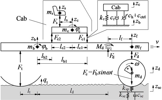
Where , , , and are the vertical displacements of the driver’s seat, cab, frame-front, frame-rear, and drum; and are the angular displacements of the cab and frame-rear; , , , and are the mass of the driver’s seat, cab, frame-front, frame-rear and drum, respectively; , , and are the vertical dynamic forces of the vibration isolations of the seat, cab, drum and wheel, respectively; and are the elastic and compression stiffness, and is the compression damper of the EPS; is the excitation of the terrain surface; is the distances of the vibratory roller, ( = 1, 2; = , , , ; , , ).
The motion equations of the soil compaction dynamic model are given by:
where , , , ,
The equation of the dynamic forces of cab hydraulic mounts is determined by [2]:
where is the damping values of HM; , and , are the stiffness and damping values of the seat suspension and the rubber of HM; is the control damping values of HM; is the relative displacements of HM are given by:
To improve the driver’s ride comfort, the damping values of the HM is then controlled based on PID-Fuzzy control.
The equations of the excitation forces of the drum () and the wheel () are also determined as follows:
where , and , are the stiffness and damping values of drum’s rubber mount and wheel.
2.2. Vibration excitations of the soil compactor
In order to determine the vertical excitation forces from the road surface on the soil compactor, two types of excitations are chosen to simulate including:
Excitation of the wheel on the terrain surface: Under the compaction condition of the soil compactor, the vehicle often travels on the poor terrain surface of off-road terrain. Therefore, to determine the poor terrain surface, the PSD of the off-road terrain in the frequency range [16, 17] was used to calculate the spatial PSD of the terrain surface. According to the ISO proposal [18], the spectral density of the off-road terrain was given by:
According to the Gaussian random process, the terrain surface roughness could be calculated through the Fourier transformation as follow:
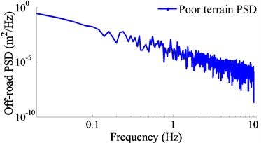
where is space frequency; is reference space-frequency; is the surface roughness coefficient; is the frequency index of the terrain surface; is the number of intervals; is a random phase uniformly distributed from 0 to 2π. According to tho the Mitschke’s research results [19, 21], a poor terrain surface of off-road terrain with = 2.14, = 3782.5×10-6 m3/cyc was used to determine the vibration excitation of the terrain on the wheel. The spectral density of the poor terrain surface in a low-frequency below 10 Hz is plotted in Fig. 2.
Excitation of the drum on the EPS: Based on the rigid drum-EPS interaction model in Refs. [6, 22], the characteristic of EPS was described by a plasticity factor and a soil damping to plasticity ratio . The excitation of the drum was then determined by:
In a vibration excitation cycle of the drum-EPS interaction, the motion of the drum on a soil patch of given density may exhibit, over each cycle of the drum, two or more often three distinct phases including (1) Loading phase: The gravel-soil ground is compressed by roller drum, the elastic stiffness and compression stiffness of the gravel-soil ground are then increased while the compression damper is decreased, (2) Unloading phase: The vibratory drum moves upward, the gravel-soil ground is then restored, and (3) Drum-Hope phase: The gravel-soil ground has become elasticity, the roller drum is easy to separate from the soil ground surface. In order to describe the relation of , and , the vibration equations of the drum on the EPS was given as follows:
By combining Eqs. 4 and 7, we can determine the vibration excitation of the drum.
Fig. 2The spectral density of a poor terrain surface
2.3. Appling PID-Fuzzy control for cab isolation system
The proportional integral derivate (PID) control is one the controller not only simple structure but also robust performance. The PID’s transfer function is written by:
where , and are the proportional, integral and derivative parameters, respectively. The PID’s performance depends on the PID’s parameters which are chosen. The well-known Ziegler-Nichols technique is used to determine the optimal values of PID, but it is efficiency only when the system works at the designed operating condition [12]. In order to solve this problem, the proportionality factors of PID is controlled by the Fuzzy control as follows:
where , and are the control parameters of the Fuzzy control in the variable ranges of the PID control of , and
The variable ranges of the PID control are chosen by 1000 ≤ ≤ 10000, 100 ≤ ≤ 1000, and 10 ≤ ≤ 100, respectively [22], their values are then replaced into Eq. 9 as follows:
By replacing Eq. 10 into Eq. 8, the PID’s transfer function is rewritten by:
In order to find the optimal proportionality factors of , and , the Fuzzy control is used to control the model.
The Fuzzy control consists of Fuzzification interface (FI), Fuzzy inference system (FIS) and Defuzzification interface (DI). First, the crisp values in FI are transformed into linguistic variables (LVs). The FIS is then used by fuzzy rule in accordance with inference rule. Finally, the LVs are transformed back to crisp values through DI for use by the physical plant [13, 20]. This paper, the relative displacement and its velocity in Eq. 3 are considered as two input variables and they are denoted by and , while the parameters of , and are the output values, and the FLC-PID control model is shown in Fig. 3.
Fig. 3PID-Fuzzy control model for subsystem
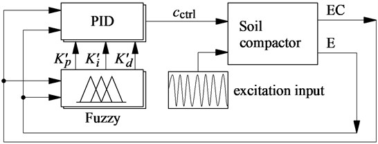
The LVs of input variables are defined by the negative big and small (nb and ns), zero (z), positive big and small (pb and ps), and of output variables are small (s), medium small (ms), medium (m), medium big (mb), and big (b); and the membership functions for their variables are represented by a fuzzy set. The shape of membership functions is the Triangular function and their values are between 0 and 1.
The if-then rules are then applied to describe according to expertise experiences and the designer’s knowledge. The fuzzy rules are listed in Table 1 and written as follows:
: if E is and EC is then is , is and is .
The FIS is selected by the minimum function and the centroid method of Mamdani [20]. This paper, we used the FIS of Mamdani for control system model.
Table 1Control rules of PID-Fuzzy control [12]
E | E | E | |||||||||||||||
EC | nb | ns | z | ps | pb | nb | ns | z | ps | pb | nb | ns | z | ps | pb | ||
nb | m | mb | b | ms | s | s | s | m | mb | S | s | m | b | mb | b | ||
ns | mb | m | m | m | ms | s | b | mb | ms | m | ms | s | m | m | s | ||
z | m | s | s | s | m | ms | ms | s | m | mb | m | b | s | s | ms | ||
ps | ms | m | ms | m | b | ms | s | m | mb | s | mb | ms | s | ms | ms | ||
pb | s | ms | m | mb | mb | m | m | ms | s | s | ms | b | s | s | m | ||
Table 2The numerical values of the EPS
EPS | (N/m) | (N/m) | (Ns/m) | |
Low-density | 0.34 | 6.44×10⁶ | 12.5×10⁶ | 70.0×10³ |
High-density | 0.87 | 283×106 | 42.3×10⁶ | 37.1×10³ |
3. Numerical simulation and result analysis
In compaction condition of the soil compactor, under the excitation force of the drum on the EPS, the characteristics of the EPS was changed from the low to medium and high-densities [3]. The effect of the medium-density on the ride comfort was researched [1, 2, 12]. To evaluate the performance of PID-Fuzzy control, two types of the EPS with low and high-densities are chosen to simulate under the excitation drum 28 and 35 Hz at a speed 5 km·h-1. The numerical values of the EPS are listed in Table 2.
Fig. 4Control results of PID-Fuzzy control on the EPS with low-density

a) Vertical driver’s seat

b) Pitching angle of cab
Fig. 5Control results of PID-Fuzzy control on the EPS with high-density

a) Vertical driver’s seat

b) Pitching angle of cab
In order to analyze the performance of cab hydraulic mounts with PID-Fuzzy control, the reduction of the maximum PSD and weighted RMS accelerations of the vertical driver’s seat and pitching cab angle are calculated in [11, 21] are chosen as the objective functions. The simulation results of the PSD accelerations of the driver’s seat and pitching cab angle with the PID-Fuzzy control at the frequencies of the drum 28 Hz and 35 Hz under the EPS with the low and high-densities are shown in Figs. 4 and 5. Under the EPS with low-density, observing Fig. 4, we can see that the PSD values with the control are clearly reduced in comparison with the passive under all the excitations of the drum 28 and 35 Hz in the low-frequency region below 10 Hz. Especially a low-frequency range below 4 Hz, the maximum PSD values of the driver’s seat and pitching cab angle with the control are greatly decreased by 28 % and 30 % at an excitation 28 Hz; and by 38 % and 67 % at an excitation 35 Hz of the vibratory drum in comparison with the passive. Similarly, under the EPS with high-density, the maximum PSD values of the driver’s seat and pitching cab angle with the control are also smaller than the passive by 26 % and 60 % at an excitation 28 Hz; and by 29 % and 58 % at an excitation 35 Hz of the vibratory drum, especially the reduction of the PSD value of the pitching cab angle at both the EPS with low and high-densities, as listed in Table 3. Therefore, the driver’s health is significantly reduced by the cab hydraulic mounts using PID-Fuzzy control in the low-frequency region below 4 Hz.
Table 3Maximum PSD values of the driver and cab
Excitation | Max-PSD | Low-density ground soil | High-density ground soil | ||||
Passive | Control | Reduction % | Passive | Control | Reduction % | ||
28 Hz | PSDz | 0.61 | 0.44 | 28 % | 0.65 | 0.48 | 26 % |
PSDφ | 0.30 | 0.21 | 30 % | 0.25 | 0.10 | 60 % | |
35 Hz | PSDz | 0.64 | 0.40 | 38 % | 0.66 | 0.47 | 29 % |
PSDφ | 0.30 | 0.10 | 67 % | 0.26 | 0.11 | 58 % | |
Table 4Reducing RMS values of PID-Fuzzy control
Reduction (Re.) % | Low-density | High-density | ||
28 Hz | 35 Hz | 28 Hz | 35 Hz | |
Re. | 26 % | 31 % | 32 % | 20 % |
Re. | 30 % | 35 % | 42 % | 52 % |
Fig. 6Weighted RMS results of PID-Fuzzy control on the EPS
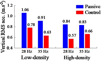
a) Vertical driver’s seat
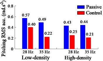
b) Pitching angle of cab
Additionally, the performance of the PID-Fuzzy control is evaluated via the weighted RMS value on the ride comfort. The comparison and simulation results of the weighted RMS values of the driver’s and cab with the control are plotted in Figs. 6(a) and (b). Observing Fig. 6, both the weighted RMS values of the driver’s seat and pitching cab angle with the control are obviously reduced comparable with the passive under the various excitations of the drum and EPSs. The results in Fig. 6(a) and Table 4 show that the weighted RMS values of the vertical driver’s seat with the control are reduced by 26 % at 28 Hz and 31 % at 35 Hz of the excitation drum on the EPS with low-density; and by 32 % at 28 Hz and 20 % at 35 Hz of the excitation drum on the EPS with high-density in comparison with the passive. Similarly, the results in Fig. 6(b) and Table 4 also show that the weighted RMS values of the pitching cab angle with the control are also lower than the passive by 30 % at 28 Hz and 35 % at 35 Hz of the excitation drum on the EPS with low-density; and by 42 % at 28 Hz and 52 % at 35 Hz of the excitation drum on the EPS with high-density. Therefore, under various compression conditions of the excitation frequencies 28 Hz and 35 Hz of the vibratory drum and on the EPS with low and high-densities of the soil compactor, both the maximum PSD and weighted RMS values of the driver’s seat and pitching cab angle are strongly reduced by using the PID-Fuzzy control. It implies that the ride comfort of the soil compactor is significantly improved by the cab hydraulic mounts with the control.
4. Conclusions
This paper, the ride comfort of the soil compactor is studied based the PID-Fuzzy control for the soil compactor cab hydraulic mounts. The main conclusions can be given by:
The ride comfort of the driver is remarkably improved by the PID-Fuzzy control under various compaction conditions of the soil compactor, especially under a low-frequency region below 4 Hz.
Both the maximum PSD and weighted RMS values of the pitching cab angle are strongly reduced with the control under different operation conditions and on the EPS with low and high-densities, especially on the EPS with high-density. Consequently, the PID-Fuzzy control not only improves the ride comfort of the soil compactor but also controls the cab shaking under various working conditions.
The research results also show that the PID-Fuzzy control is not only effective for vehicles moving on the rigid roads, but also effective for vehicles moving on off-road roads.
References
-
Kordestani A., Rakheja S., et al. Analysis of ride vibration environment of soil compactors. SAE International Journal of Commercial Vehicles, Vol. 3, 2010, p. 259-272.
-
Nguyen V., Zhang J., et al. Vibration analysis and modeling of an off-road vibratory roller equipped with three different cab’s isolation mounts. Shock and Vibration, Vol. 2018, 2018, p. 1-17, https://doi.org/10.1155/2018/8527574.
-
Adam D., Kopf F. Theoretical analysis of dynamically loaded soils. Proceedings of the European Workshop Compaction of Soils and Granular Materials, Paris, France, 2000, p. 207-217.
-
Li J., Zhang Z., et al. Dynamic characteristics of the vibratory roller test-bed vibration isolation system: simulation and experiment. Journal of Terramechanics, Vol. 56, 2014, p. 139-156, https://doi.org/10.1016/j.jterra.2014.10.002.
-
Paul J., Michael A. Capturing nonlinear vibratory roller compactor behavior through lumped parameter modeling. Journal of Engineering Mechanics, Vol. 134, 2008, p. 684-693, https://doi.org/10.1061/(ASCE)0733-9399 (2008)134:8(684).
-
Nguyen V., Zhang J., et al. Ride quality evaluation of the soil compactor cab supplemented the auxiliary hydraulic mounts via simulation and experiment, Journal of Southeast University, Vol. 35, Issue 3, 2019, p. 273-280, https://doi.org/10.3969/j.issn.1003-7985.2019.03.001.
-
International Organization for Standardization, Mechanical vibration and shock-evaluation of human exposure to whole body vibration – Part 1: General requirements. ISO 2631-1:1997, Geneva, Switzerland, 1997.
-
Marzbani H., Jazar R., et al. Hydraulic engine mounts: a survey. Journal of Vibration and Control, Vol. 20, 2010, p. 1439-1463, https://doi.org/10.1177/1077546310380432.
-
Wang M., et al. A novel design of semi-active hydraulic mount with wide-band tunable notch frequency. Journal of Vibration and Control, Vol. 333, 2014, p. 2196-2211, https://doi.org/10.1016/j.jsv.2013.12.004.
-
Lee P., Vogt J., Han S. Application of hydraulic body mounts to reduce the freeway hop shake of pickup truck. SAE Technical Paper Series, 2009, https://doi.org/10.4271/2009-01-2126.
-
Nguyen V., Nguyen K. Enhancing the ride comfort of the off-road vibratory roller cab by adding damper hydraulic mount. Vibroengineering Procedia, Vol. 21, 2018, p. 89-95, https://doi.org/10.21595/vp.2018.20339.
-
Nguyen V., Zhang J., Yang X. Low-frequency performance analysis of semi-active cab’s hydraulic mounts of an off-road vibratory roller. Shock and Vibration, Vol. 2019, 2019, p. 1-15, https://doi.org/10.1155/2019/8725382.
-
Nguyen V., Zhang J., Le Q., et al. Performance analysis of air suspension of heavy truck with semi-active fuzzy control. Journal of Southeast University (English Edition), Vol. 33, 2017, p. 159-165, https://doi.org/10.3969/j.issn.1003-7985.2017.02.006.
-
Félix-Herrán L., Mehdi D., Rodríguez-Ortizc J., et al. Hinf control of a suspension with a magnetorheological damper. International Journal of Control, 2012, p. 1366-5820, https://doi.org/10.1080/00207179.2012.674216.
-
Nguyen S., et al. A hybrid clustering based fuzzy structure for vibration control – Part 2: An application to semi-active vehicle seat-suspension system. Mechanical systems and signal processing, Vol. 450, 2015, p. 288-301, https://doi.org/10.1016/j.ymssp.2014.10.019.
-
Wong J. Theory of Ground Vehicles. John Wiley and Sons, New York, NY, USA, 2001.
-
Robson J. Road surface description and vehicle response. International Journal of Vehicle Design, Vol. 1, 1979, p. 25-35, https://doi.org/10.1504/IJVD.1979.061223.
-
International Organization for Standardization. Reporting Vehicle Road Surface Irregularities. ISO/TC108/SC2/WG4 N57, Tieme Medical Publishers, Stuttgart, Germany, 1982.
-
Mitschke M. Dynamik der Kraffahrzeuge. Springer-Verlag, Berlin, Germany, 1972.
-
Mamdani H. Assilian An Experiment in linguistic synthesis with a fuzzy logic controller. International Journal of Man-Machine Studies, Vol. 7, 1975, p. 1-13, https://doi.org/10.1016/S0020-7373(75)80002-2.
-
Nguyen V., Zhang J., Jiao R., et al. Effect of the off-road terrains on the ride comfort of construction vehicles. Journal of Southeast University (English Edition), Vol. 35, 2019, p. 191-197, https://doi.org/10.3969/j.issn.1003-7985.2019.02.008.
-
Nguyen V., Zhang J., et al. Performance analysis of semi-active hydraulic system of the off-road vibratory roller cab using optimal fuzzy-PID control. Journal of Southeast University, Vol. 35, Issue 4, 2019, p. 1-9, https://doi.org/10.3969/j.issn.1003-7985.2019.04.001.
Cited by
About this article
This study is supported by Hubei Polytechnic University Teaching and Research Projects (No. 19XJK17R).
