Abstract
This study focuses on the comparison of the performance of two unsymmetrical hydrofoils, NACA 4424 and MHKF-240 at 60 angle of attack under cavitation. The Schnerr and Sauer cavitation model along with Realizable k-ε turbulence model is used for numerical computation in commercial software ANSYS Fluent. The lift, drag and pressure coefficients for different cavitation numbers were studied. Among both the hydrofoils MHKF-240 gives a higher lift coefficient which is the parameter of better performance.
1. Introduction
Cavitation is a phenomenon of formation and subsequent collapse of vapor bubbles that form in the liquid flow when the local pressure falls below the saturated vapor pressure. The inception of cavitation in flow causes severe structural damage due to noise, vibration, and erosion making it complex and interesting area for research [1]. Cavitation instabilities may be of different types such as cavitation surge, rotating cavitation, asymmetric cavitation, and high order instabilities. The cavitation phenomenon can be commonly observed around the hydrofoils and propellers in a marine application.
The hydrofoil is the streamlined body designed in such a way that it can provide sufficient lift required by the ship to move on water. This lift force produced on the hydrofoil is due to the pressure difference between the lower and upper surface of the hydrofoil as the upper side of hydrofoil is having lower pressure. This lower pressure can cause the problem of cavitation. By nature, a cavitating flow is always an unsteady three-dimensional flow and to study the cavitation on the hydrofoil various experimental and numerical studies have been reported in the literature. Fabula [2] has applied Thin-Aerofoil theory and closure-singularity cavity termination method on thin hydrofoil for steady, plane irrotational and incompressible flow to know the phenomenon of cavity termination along with the wake thickness for a different angle of attack. His theoretical results for lift and drag force on the cavitating aerofoil are found to be in good agreement with the experimental results. Similarly, Woods [3] studied the unsteady cavitating flow past a finite length two-dimensional flat plate hydrofoil and symmetrical wedge to understand the feature of cavity growth and required sink for the accommodation of displaced liquid.
The occurrence of cavitation can be quantitatively measured by a non-dimensional parameter, termed as cavitation number (σ), which is essentially a measure of how close the pressure in liquid flow is to vapor pressure. Mathematically, the cavitation number is defined as σ=(p∞-pv)/(0.5ρU2∞), where p∞ is the reference pressure, pv is the vapor pressure of the liquid, ρ is the density and U∞ is the free stream velocity of liquid flow [4]. Cavitation number is also an important parameter to determine the cavity length on the hydrofoil, as lower the cavitation number more will be the cavity length and below certain value of σ the complete hydrofoil is engulfed in the cavity bubble. This phenomenon is known as supercavitation which greatly reduces the skin friction drag on hydrofoil. Green [5] extended thin aerofoil theory on two supercavitating flat-plate hydrofoils at an angle γ1 for upper wetted surface and γ2 on the lower wetted surface in the presence of a free surface using two-dimensional, incompressible, irrotational, linearized flow model. In addition to cavitation number the cavitation behaviour is also influenced by the Reynold’s number as in many instances the local pressure reduces as the result of accelerating high velocity.
The NACA aerofoil developed by National Advisory Committee for Aeronautics (NACA) are the profiles used for aircraft wings, ship propellers and hydrofoils. The computational investigation of the performance of different NACA profiles under cavitation has been the topic of intense research in the past. To improve the performance and structural stability of hydrofoils, some researchers have modified these NACA profiles. Recently, Shiu et al. [6] has modified different NACA44 hydrofoils by adding finite thickness to the trailing edge and named the hydrofoil as Marine and Hydrokinetic (MHKF1) hydrofoils and then compared the performance of MHKF1 for different angle of attack with NACA 44 series using both experimental and numerical method. They concluded that these modified hydrofoils give higher lift coefficients. They have focused on cavitating phenomenon with respect to change in angle of attack but not mentioned the cavitation behaviour and hydrofoil performance related to different cavitation number.
In this paper, the comparison of the performance of NACA 4424 and MHKF-240 hydrofoil for different cavitation numbers (σ) has been presented. The angle of attack used is 6° as internal parametric studies gives the stall condition for NACA 44 series at 6°. The MHKF-240 hydrofoil is designed by adding finite thickness to the sharp training edge of NACA 4424 hydrofoil. The two-phase single fluid homogeneous mixture approach with Schnerr and Sauer cavitation model [7] is used and to study the turbulent flow dynamics the Realizable k-ε turbulence model is applied [8]. The chord length of both the hydrofoils is 100 mm and span is considered as a unity. The results of NACA4424 and MHKF-240 are compared and it was found that the lift coefficient of MHKF-240 has higher value as expected.
2. Governing equations
The mass conservation equation and momentum equation are the governing equations for two phase flow [9]:
where mixture density (ρm) is related to vapor volume fraction (αv) as:
where p is the pressure, ρv and ρl are the vapor and liquid phase densities. The effective viscosity in Eq. (2) is expressed as μeff=μ+μt where μ is the molecular viscosity and μt is the turbulent viscosity which is modelled using different turbulence model. For k-ε turbulence models:
In this equation k is the turbulent kinetic energy and ε is dissipation of kinetic energy and Cμ is the model constant.
3. Computational method
The commercial CFD simulation software ANSYS Fluent is used to numerically solve two-phase cavitating flow on the NACA 4424 and MHKF-240 hydrofoil at 6° angle of attack for different cavitation numbers (σ). NACA 4424 hydrofoil is having chord length of 100 mm, maximum camber of 4 % at 0.4 chords from the leading edge with maximum thickness of 24 % of the chord. The MHKF-240 is having the same chord length but with the finite thickness (2.5455 mm) at the trailing edge [6]. Fig. 1 shows the profile of both the hydrofoils.
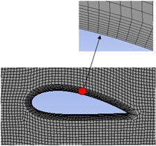
To know the hydrodynamic behaviour of the hydrofoils under the cavitation phenomenon the C type domain is made around the hydrofoil having a size of 1800 mm×1500 mm, extending 13.5 times the chord length ahead of leading edge and 12 times the chord length behind the leading edge [10]. The computational domain with the required dimensions and boundary conditions is shown in Fig. 2. The Dirichlet boundary condition is given to the domain with C type boundary in the upstream as velocity inlet with freestream velocity in x- direction as 7.03 m/s. The outlet is given as pressure outlet and all other boundaries including hydrofoil is given no-slip condition. The Reynold’s number (Rec) based on the chord length is 0.69×10⁶ [11]. The domain is meshed using unstructured quadrilateral elements and to create the denser mesh around the hydrofoil the sphere of influence is provided as shown is the Fig. 3. To obtain higher computational accuracy the inflation layers are generated around the hydrofoil as shown in Fig. 4.
The pressure based transient mixture model is used for solving the governing equations. The realizable k-ε turbulence model [12] and Schnerr and Sauer cavitation model is used to calculate the μt and αv respectively. For pressure and velocity coupling Coupled method is used. Here the momentum, volume fraction, turbulent kinetic energy and turbulent dissipation rate are solved using QUICK scheme whereas pressure is computed using PRESTO!
Fig. 1NACA 4424 and MHKF-240 hydrofoil profile
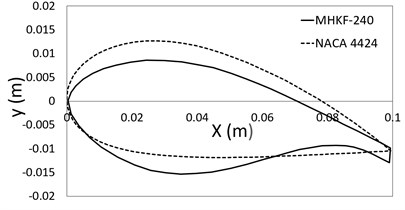
Fig. 2Computational domain with boundary conditions
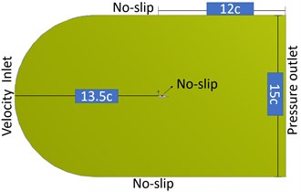
Fig. 3Meshing in computational domain
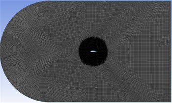
Fig. 4Inflation layers around the hydrofoil
4. Results and discussions
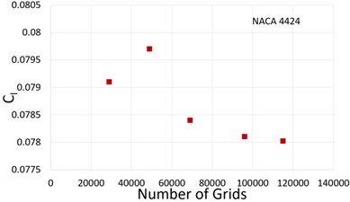
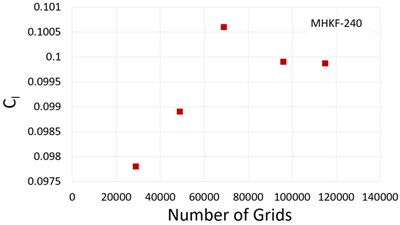
The independency of mesh is an important parameter for optimum computational cost without compromising the accuracy of the solution. The grid independence test was performed for both the hydrofoils at σ=1.5 and α=6°. The time-averaged lift coefficient and percentage error for all grids concerning the finest grid E are presented in Table 1. and it can be seen that error between grid D and grid E for both the hydrofoils is minimum. Hence, grid D with 96000 elements has been selected as the final mesh for studying the hydrodynamic behaviour of both hydrofoils at different cavitation numbers. The plots for lift coefficient for different grid size are shown in Fig. 5.
Table 1Time averaged lift coefficient for different grids
S. No | No of grids | Time averaged lift coefficient (Cl) NACA 4424 | Time averaged lift coefficient (Cl) MHKF-240 | Percentage error related to 115000 grids (Cl) NACA 4424 | Percentage error related to 115000 grids (Cl) MHKF-240 |
A | 29000 | 0.0791 | 0.0978 | 1.4 | 1.91 |
B | 49000 | 0.0797 | 0.0989 | 2.18 | 0.80 |
C | 69000 | 0.0784 | 0.1006 | 0.512 | 0.90 |
D | 96000 | 0.0781 | 0.0999 | 0.128 | 0.20 |
E | 115000 | 0.0780 | 0.0997 | – | – |
Fig. 5Time averaged lift coefficient against the grid numbers
The pressure coefficient Cp as a result of pressure distribution on the hydrofoil is represented in Fig. 6 on the suction side of both NACA 4424 and MHKF-240 hydrofoil for σ= 1.28 and α= 6°. The straight line on both the plots represents the cavity length on the hydrofoil. The cavity length of MHKF-240 foil is more as compared to NACA 4424 hydrofoil as more bubble formation takes place towards the leading edge due to more pressure drop on the suction side.
Fig. 6Pressure coefficient at the suction side of hydrofoil along the chord length
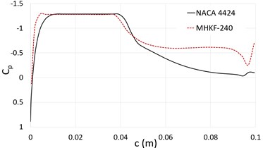
Fig. 7Time averaged (3 sec) lift coefficient for different cavitation numbers
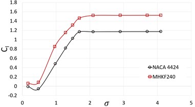
The comparison of lift coefficient on NACA 4424 and MHKF-240 hydrofoil is plotted in Fig. 7 for the range of cavitation number from 0.17 to 4.12. For calculating the lift coefficient, we normalized our results with the chord length of NACA 4412 in the literature [11]. Here, it can be observed that lift coefficient of MHKF-240 is higher as compared to NACA 4424 resulting in higher hydrodynamic performance. The other parameter to check the performance of hydrofoil is the (l/d)max value which is computed based on the wetted area of hydrofoil [13]. MHKF-240 have higher (l/d)max giving better performance as compared to NACA 4424 profile. In Fig. 8 and Fig. 9 vapor volume fraction on NACA 4424 and MHKF-240 hydrofoil is shown for α=6° and σ= 1.28. We observed that cavity on MHKF-240 starts nearer to the leading edge and had larger cavity length and more vapor fraction as compared to NACA 4424 which results in the lower skin friction drag coefficient on MHKF-240 which is described next section.
Fig. 8Vapor volume fraction on NACA 4424 hydrofoil at σ= 1.28
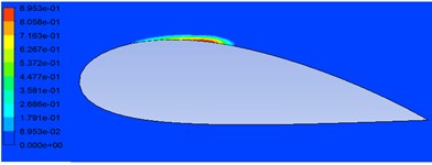
Fig. 9Vapor volume fraction on MHKF-240 hydrofoil
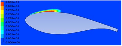
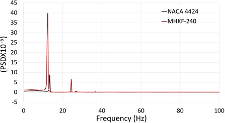
The skin friction drag is the resisting force due to the viscosity of fluid on the object. Fig. 10 represents the skin friction coefficient on the upper side of both the hydrofoils. As the flow separation on the MHKF-240 foil near the leading edge is more there is less viscous resistance due to fluid. In Fig. 11 the time evolution of lift coefficients between 1.9 sec to 3for both the hydrofoils atσ=1.28 is shown which is later used to compute the Strouhal number using Fast Fourier Transformation (FFT) of the lift coefficient.
Fig. 10Skin friction coefficient at the suction side of hydrofoil
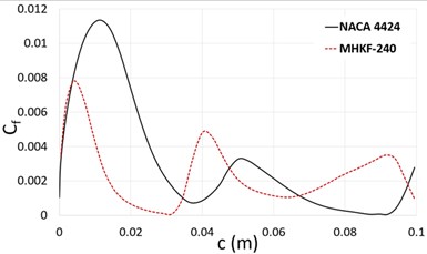
Fig. 11Time evolution of lift coefficient
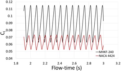
To understand the nature of the shedding of the cloud cavity the Strouhal number (St) is used as an important parameter that defines the impact of unsteady oscillations on the flow [14]. To calculate the Strouhal number FFT algorithm is used which converts the signal from a time domain to frequency domain. Fig. 11 shows the power spectral density of the lift coefficient forσ= 1.28 giving the first peak value for NACA 4424 at 13.3 Hz and for MHKF-240 at 12.3 Hz. Based on the chord length of hydrofoil and peak value of frequency we get St for NACA 4424 as 0.189 and MHKF-240 as 0.175.
Fig. 12Power spectral density of lift coefficient versus frequency
5. Conclusions
In this paper, the cavitation occurrence on NACA 4424 and MHKF-240 hydrofoil is been examined for different cavitation numbers at 6° angle of attack. The optimum mesh size on both the hydrofoils was determined and numerical simulation was performed using commercial software ANSYS Fluent to obtain lift coefficient, skin friction drag coefficient, pressure coefficients and Strouhal number. From these results, it is concluded that:
1) Lift coefficient of MHKF-240 hydrofoil is more as compared to NACA 4424 giving higher performance.
2) Vapor volume fraction of MHKF-240 is higher resulting in lower skin friction drag.
3) Strouhal number for NACA 4424 is 0.189 and for MHKF-240 is 0.175 due to lower vapor shedding frequency on MHKF-240.
References
-
Ganz S. Cavitation: Causes, Effects, Mitigation and Application. Rensselaer Polytechnic Institute, 2012.
-
Fabula A. G. Thin-airfoil theory applied to hydrofoils with a single finite cavity and arbitrary free-streamline detachment. Journal of Fluid Mechanics, Vol. 12, Issue 2, 1962, p. 227-240.
-
Woods L. C. On the theory of growing cavities behind hydrofoils. Journal of Fluid Mechanics, Vol. 19, Issue 1, 1964, p. 124-136.
-
Franc J. P., Michel J. M. Unsteady attached cavitation on an oscillating hydrofoil. Journal of Fluid Mechanics, Vol. 193, 1988, p. 171-189.
-
Green T., Street R. L. Two supercavitating hydrofoils near a free surface. Journal of Fluid Mechanics, Vol. 27, Issue 1, 1967, p. 1-28.
-
Shiu H., van Dam C. P., Johnson E., Barone M., Phillips R., Straka W., Fontaine A., Jonson M. A design of a hydorofoil family for current-driven marine-hydorkinetic turbines. 20th International Conference on Nuclear Engineering and the ASME Power Conference, 2012.
-
Niedzwiedzka A. Homogeneous cavitation modeling-analysis of basics of homogeneous cavitation modeling – analysis of basics of mathematical. Modelowanie Inżynierskie, Vol. 65, 2017, p. 75-82.
-
Huang S., He M., Wang C., Chang X. Simulation of cavitating flow around a 2-D hydrofoil. Journal of Marine Science and Application, Vol. 9, Issue 1, 2010, p. 63-68.
-
Saha K. Modelling of cavitation in nozzles for diesel injection applications. UWSpace, 2014, http://hdl.handle.net/10012/8628.
-
Kumar T. R. S., Vidyapeetham A. V., Ramakrishnananda B., Vidyapeetham A. V., Arulkrishnan A. Numerical investigation of two element camber morphing airfoil in low Reynolds number flows. Journal of Engineering Science and Technology, Vol. 12, Issue 7, 2017, p. 1939-1955.
-
Kermeen R. W. Water tunnel tests of NACA 4412 and Walchner profile 7 hydrofoils in noncavitating and cavitating flows. Rep. No 47-5, 1956.
-
Shih T. H., Liou W. W., Shabbir A., Yang Z., Zhu J. A new K-Ε{lunate} eddy viscosity model for high Reynolds number turbulent flows. Computers and Fluids, Vol. 24, Issue 3, 1995, p. 227-238.
-
Loftin Laurence K. Quest for Performance: The Evolution of Modern Aircraft. National Aeronautics and Space Administration, 2012.
-
Dular M., Bachert R. The issue of Strouhal number definition in cavitating flow. Strojniski Vestnik/Journal of Mechanical Engineering, Vol. 55, Issue 11, 2009, p. 666-674.
