Abstract
In this paper, numerical investigation is carried out on two-dimensional Ahmed body model using Computational Fluid Dynamics in ANSYS Fluent 19.1. The 2-D model is designed in Catia v5 for 25°, 35° and 45° slant angles. The turbulent model used to analyze the flow dynamics is Realizable k-ε model. The drag coefficient variation with respect to slant angle is computed. The skin friction coefficient, wall shear stress and frictional velocity are also calculated.
1. Introduction
The flow around any vehicle is primarily of turbulent nature and it is observed by the large-scale separations and reverse flow characteristics on the vehicle. To develop any new model of the vehicle it is necessary to understand the flow dynamics around it. Ahmed body is considered as the base problem for the analysis of flow dynamics for all the four-wheel vehicles using computational fluid dynamics (CFD) both experimentally and numerically. The aerodynamic drag force is an important parameter to analyze the performance of the vehicle, and the automotive industry always tries to reduce the drag force to improve fuel efficiency. Based on the literature it was found that 10 % reduction in drag force reduces fuel consumption by 7 % [1]. The drag force induced is the sum of the frictional drag and pressure drag. The friction drag is developed due to the viscosity of air related to Reynold’s number, and pressure drag is due to eddies formation on the body passage along the wake formation.
Ahmed et al. [2] developed the three-dimensional simplified model of the vehicle for a better understanding of flow dynamics as the real-life vehicles are complex to study, both experimentally and numerically. The ideal design of Ahmed body is having length (1044 mm), height (288 mm), width (389 mm) and constant slant length (222 mm) long, for any angle at the rear part of the body. The aerodynamic drag is found to influence by the slant part of the vehicle.
Guilmineau [3] did the simulation on Ahmed body at 25° and 35° slant angles with and without stilts using different turbulent models and compared their results with the experimental data in the literature. They concluded that for 35° the presence of stilts increases the drag force. Wang et al. [1] modified the Ahmed body surface to reduce the drag force by providing the non-smooth dimples on it. The effect of dimples was analyzed by the wake flow structure at the downstream side, and their model leads to reduction of coefficient of drag by 5.20 %. Similarly, Keogh et.al [4] focused on the corning of the Ahmed body. He provided the corner at both the rear and front part of the model and checked the overall performance of the model. He concluded that the drag coefficient can be reduced by lowering the corner radius. Hanfeng et al. [5] used the deflector on the rear side of Ahmed body by keeping slant angle as 25° and tried to increase the fuel efficiency by reducing the drag force. He also concluded that drag force depends both on the height and length of the deflector.
Khan and Umale [6] fabricated an ideal solid 3-D model of Ahmed body at 25° and 35° slant angles and performed both experiments and numerical simulation on it, and compared both the results for better understanding. For both experiments and simulation, he observed that drag force increases on increasing the slant angle. He also analyzed the effect of front radius and ground clearance on the performance of vehicle.
This present work is focused on the numerical analysis of drag coefficient on increasing the slant angle of 2-D Ahmed body using commercial software ANSYS Fluent 19.1. Three different slant angles i.e. 25°, 35° and 45° are used by keeping the slant length constant. The turbulent model used is Realizable k-ε and pressure velocity coupling method is SIMPLE. The results in the form of drag coefficient, pressure coefficient, pressure contours and velocity streamlines are presented in the results and discussion section.
2. Governing equations
The two-dimensional continuity equation and momentum equation are solved as governing equations [7].
Continuity equation is given in Eq. (1):
Momentum equations are given in Eq. (2) and Eq. (3).
For X-direction component:
For Y-direction component:
where, p is the pressure, ρ is the density, μ is the dynamic viscosity of fluid, u and v are the velocities in x and y directions respectively.
3. Geometry description
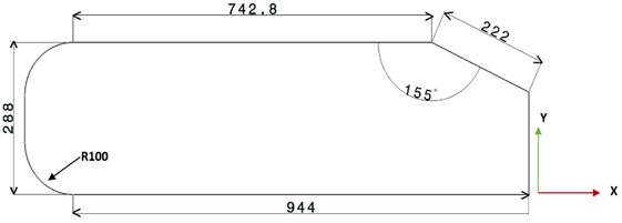
We choose Catia v5 software to design our 2D Ahmed body model. All the dimensions are given in mm, based on the standard problem given in the literature [2]. Table 1 shows all the required dimensions for the Ahmed body and the fluid domain enclosing it. The numerical simulation is done for three different slant angles i.e. 25°, 35° and 45°. In Table 2 all the computed values of different dimensions for all the three slant angles is mentioned [8]. The model of two-dimensional Ahmed body for slant angle (ϕ= 25°) is shown in Fig. 1.
Table 1Geometrical dimensions
Length | 1044 mm |
Height | 288 mm |
Front radius | 100 mm |
Ground clearance | 50 mm |
Slant angles (ϕ) | 25°, 35°, 45° |
Fluid domain | 8264 mm×2000 mm |
X is total length of Ahmed body – the horizontal distance covered by slant, Z is total height of the Ahmed body – vertical distance covered by slant:
Table 2Calculated dimensions for all the cases
Slant angle (ϕ) | L (mm) | H (mm) | X (mm) | Z (mm) |
25° | 201.20 | 93.82 | 842.79 | 194.17 |
35° | 181.85 | 127.33 | 862 | 160.67 |
45° | 156.97 | 156.97 | 887.03 | 131.03 |
Fig. 1Geometry of 2-D Ahmed body
4. Computational domain and meshing
The 2-D control volume is created around the Ahmed body for analysis of aerodynamic effects using computational fluid dynamics in commercial software ANSYS Fluent. The domain is having dimensions as 8264 mm×2000 mm. Fig. 2 represents the computational domain with 40 m/s velocity at the inlet and the atmospheric pressure (101325 Pa) at the outlet. Remaining walls are under no slip condition. The turbulent model used to solve the flow dynamics is Realizable k-ε and method for pressure velocity coupling is SIMPLE [9].
Fig. 2Domain around the Ahmed body

For meshing, triangular elements are used with refined mesh around the Ahmed body using face split tool in the geometry. In Fig. 3 the meshing with inflation layers on the Ahmed body is shown. For all three cases mesh is kept same with 72000 number of grids.
Fig. 3Meshing around the Ahmed body with inflation layers

5. Results and discussion
The drag coefficient along the number of iterations for all the three slant angles is shown in Fig. 4. Initially the flow has instabilities due to which Cd curves have fluctuating values but as the number of iterations increases the values get stabilized. Fig. 5 represents averaged value of drag coefficient at 25°, 35° and 45° slant angles. It is seen that on increasing the slant angle, the value of drag force increases. Hence the performance of the Ahmed body decreases.
Fig. 4Drag coefficient along the iterations for ϕ
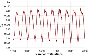
a)ϕ=25°
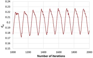
b)ϕ=35°
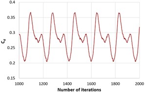
c)ϕ=45°
Fig. 5Averaged value of drag coefficient for ϕ= 25°, 35°, 45°
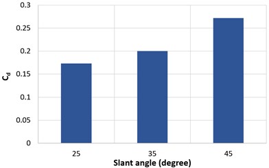
Fig. 6Pressure coefficient Cp along the length of the Ahmed body for ϕ= 25°
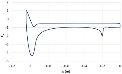
Fig. 6 represents the pressure coefficient (Cp) plot of the ahmed body along its length. The maximum value of Cp is unity at the front part on the lower side of the Ahmed body as all the kinetic energy is converted into pressure energy while, negative values are representing Cp on the upper side of the body. There is sudden drop in pressure at the slant surface (–0.2 m) on Cp curve. Fig. 7 shows the pressure contours for all three-slant angles of Ahmed body. It can be concluded that maximum pressure is at the curved front part. Similarly, Fig. 8 depicts the velocity streamlines on the Ahmed body, which represents the velocity variation on changing the slant angle. Most of the drag on the Ahmed body is due to the downstream flow separation, and as the slant angles increases the recirculation region also increases.
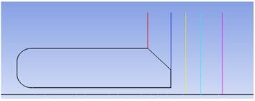
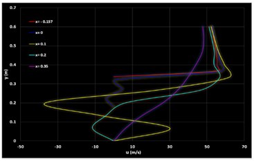
Fig. 9 depicts the u-velocity profiles (ϕ=45°) along the vertical lines at different locations (x= –0.157 m, 0 m, 0.1 m, 0.2 m, 0.35 m) starting from the initial point on the slant of Ahmed body and remaining lines on the recirculation regions in the downstream. The velocity at (x=0.1 m) location has the sharp negative value due to formation of vortices.
Fig. 7Pressure contours for different ϕ: a) 25°, b) 35°, c) 45°
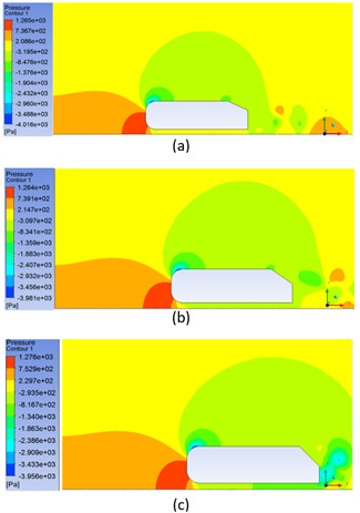
Fig. 8Velocity streamlines for different ϕ: a) 25°, b) 35°, c) 45°
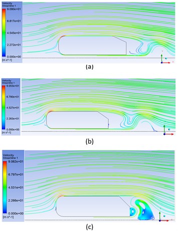
Fig. 9u-velocity along the vertical lines at different
The Reynold’s number (Re) based on the characteristic length of the Ahmed body i.e. 288 mm and the freestream velocity of 40 m/s at the inlet is:
The skin friction, wall shear stress and friction velocity calculated based on this Re are calculated as below.
Skin-Friction coefficient (Cf):
Wall shear stress (τw):
Friction velocity (u*):
6. Conclusions
In the present work, numerical computation of flow dynamics around the 2-D Ahmed body car model for three different slant angles 25°, 35° and45° is produced. The drag coefficient was found to increase with increase in the slant angles due to the development of recircular region at the downstream side of the Ahmed body. The percentage increase in drag coefficient is 57 % on varying the slant angle from 25° to 45°. In future, we will work on the numerical computation of flow behaviour around the 3-D Ahmed car body using different turbulent models.
References
-
Wang Y., Wu C., Tan G., Deng Y. Reduction in the aerodynamic drag around a generic vehicle by using a non-smooth surface. Proceedings of the Institution of Mechanical Engineers, Part D: Journal of Automobile Engineering, Vol. 231, Issue 1, 2017, p. 130-144.
-
Ahmed S., Ramm G., Faltin G. Some salient features of the time-average ground vehicle wake. SAE Technical Paper 840300, 1984, https://doi.org/10.4271/840300.
-
Guilmineau E. Computational study of flow around a simplified car body. Journal of Wind Engineering and Industrial Aerodynamics, Vol. 96, Issues 6-7, 2008, p. 1207-1217.
-
Keogh J., Barber T., Diasinos S., Graham D. The aerodynamic effects on a cornering Ahmed body. Journal of Wind Engineering and Industrial Aerodynamics, Vol. 154, 2016, p. 34-46.
-
Hanfeng W., Yu Z., Chao Z., Xuhui H. Aerodynamic drag reduction of an Ahmed body based on deflectors. Journal of Wind Engineering and Industrial Aerodynamics, Vol. 148, 2016, p. 34-44.
-
Salahuddin Khan R., Umale S. CFD aerodynamic analysis of Ahmed body. International Journal of Engineering Trends and Technology, Vol. 18, Issue 7, 2014, p. 301-308.
-
Singh S., Danish M., Saha K., Ranjan V. Numerical simulation of Vortex-Shedding from NACA4418 hydrofoil. Vibroengineering Procedia, Vol. 21, 2018, p. 125-130.
-
Thabet S., Thabit T. H. CFD simulation of the air flow around a car model (Ahmed body). International Journal of Scientific and Research Publications, Vol. 8, Issue 7, 2018, p. 517-525.
-
Bella G. On the rans modeling of turbulent airflow over a simplified car model. Fluids Engineering Division Summer Meeting, 2016.

