Abstract
Damage growth monitoring plays an important role in providing early warning of structural failure. The existing methods for damage growth monitoring are mainly local inspection methods, such as acoustic emission. These methods need a priori knowledge of accessible damage vicinity, which may not be realized in practice. Hence, vibration-based global approach is adopted to overcome these difficulties. Natural frequency, as a global modal parameter, can be measured easily and is used for vibration-based damage growth monitoring in this study. A concept of damage-induced relative natural frequency change (RNFC) curve is defined first and its relation with mode shape is then derived analytically, giving a good way to approximate RNFC curves. For monitoring damage growth, a damage growth indicator is proposed based on RNFCs between two damaged stages of a beam. The effectiveness of the indicator for damage growth monitoring is proved by both numerical and experimental cases in beam-like structures.
1. Introduction
Structural health monitoring (SHM) is a promising research field for maintaining structural health. SHM methods mainly focus on damage diagnosis including damage localization and severity evaluation [1, 2]. In comparison, less attention has been paid to damage growth monitoring, which plays an important role in providing early warning of structural failure.
The relevant literature regarding damage growth monitoring is summarized here. Bakuckas et al. [3] studied the use of acoustic emission (AE) to monitor damage growth in laminates. Daniel et al. [4] adapted AE technique for fatigue damage growth monitoring in metals. Maillet et al. [5] combined acousto-ultrasonics and AE for damage evolution monitoring in minicomposites. Chen et al. [6] used acoustography for real-time monitoring of fatigue damage growth in composites. Kumar et al. [7] used rotating frequency changes as an indicator to monitor damage growth in turbine blades. There are some other techniques used for damage growth monitoring, including thermography [8, 9], guided waves [10, 11], and digital image correlation [12, 13]. It is seen that the existing methods for damage growth monitoring are mainly local inspection methods. Such methods need a priori knowledge of accessible damage vicinity, which is not practical in many applications.
Natural frequency, as a global modal parameter, has been widely used for damage detection [14-17] based on natural frequency changes between intact and damaged stages of structures. In this paper, a simple indicator based on relative natural frequency changes (RNFCs) is formulated for damage growth monitoring from any reference state to the current state in beam-like structures. The proposed method holds the promise of developing a real-time monitoring technique.
2. Theoretical analysis
2.1. Damage-induced RNFC curves
The fundamental frequency of a beam can be obtained based on Rayleigh’s method [18]. The maximum values of kinetic energy Tmax and potential energy Umax of a beam are expressed as:
where ω is the fundamental frequency, ˉm is the linear density, ϕ is the fundamental mode shape, ζ is the dimensionless coordinate, E is the modulus of elasticity, and I is the moment of inertia. By equating Tmax and Umax, the fundamental frequency is derived as:
Damage is modeled by stiffness reduction at the position of damage. When a decrement in E occurs at ζi (the coordinate of damage i), the corresponding frequency of the damaged beam can be calculated as:
where δE(ζi) represents an increment in E at ζi. The following relation is then derived from Eq. (3) and (4):
The RNFC, denoted by Δω(ζi), is approximated from Eq. (5) as:
It is seen that the RNFC can be represented as a function of damage location and severity. Δω(ζi) is rescaled by min-max normalization:
Δˉω(ζi) is defined as RNFC curve and denoted as g(ζi). The RNFC can be written as:
Natural frequencies of a beam at damage stages I and II with severity s1 and s2 are denoted as ωd1(ζi) and ωd2(ζi), respectively. The following equations can be obtained according to Eq. (8):
This means that the relation in Eq. (8) remains true when the reference frequency is from a damage state of a beam.
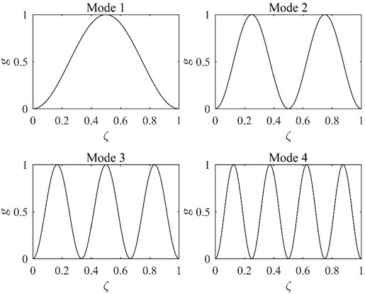
From Eq. (6) and (7), g is obtained by min-max normalization of (ϕ'')2. Similarly, the Rayleigh’s quotient is applied to higher modes of vibration and then each mode of g is obtained in the same way. The mode shapes of a SS beam are written as [19]:
where j is the number of mode, λj=jπ. The first four modes of g are plotted in Fig. 1.
Fig. 1First four modes of g for the SS beam

2.2. Damage indicator
Natural frequencies of a beam at damage stages I and II are given by ωd1j and ωd2j, respectively. Proposed indicator is created step by step [20].
Calculation of the RNFCs:
Min-max normalization of Δωj:
If max(Δωj) is equal to min(Δωj), let Δˉωj=0.
Definition of damage growth position function (DGPF):
Calculation of the Bayesian probability by fusing m DGPFs according to Bayes formula [21]:
Improvement of Bayesian probability:
Z-score normalization:
where ˉQ is the mean of Q and σ is its standard deviation.
Formulation of damage growth indicator (DGI):
3. Numerical verification
A finite element model consisting of 200 elements is developed to simulate a SS beam. The geometrical parameters of the specimen are 1000×30×2 mm3. The material properties are as follows: modulus of elasticity 69 GPa, and density 2720 kg/m3. Damage is first induced via a 5 % reduction in the modulus of elasticity of the 30th element. Then the damage severity is increased to 10 %. The first 5 natural frequencies of the specimen at two damage stages are calculated as shown in Table 1.
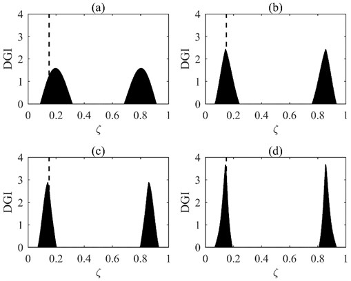
Fig. 2DGIs obtained by fusing first: a) 2, b) 3, c) 4, and d) 5 DGPFs

The DGIs are calculated by fusing the first 2, 3, 4, and 5 DGPFs (Fig. 2). The real damage growth position is marked in dashed lines. It is clear from Fig. 2 that the monitoring precision and resolution maintain an increasing trend with the increase in the number of fused DGPFs. It should be noted that this method always shows damage growth positions symmetrically because of the symmetry in the structure [14, 20].
Table 1Natural frequencies of the damaged beam at two stages (Hz)
Severity | 1 | 2 | 3 | 4 | 5 |
5 % | 4.567 | 18.267 | 41.097 | 73.060 | 114.162 |
10 % | 4.567 | 18.264 | 41.086 | 73.040 | 114.144 |
4. Experimental validation
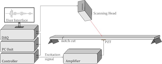
A test is conducted on a SS aluminum beam. The dimensions of the beam are 1000×30×3 mm3. Three damage stages (I, II, and III) are created. In Stage I, a through-thickness crack is cut to 3 mm in depth at the location 53 mm (ξ= 0.053) from the left end. In Stages II and III, the crack is extended to 6 and 12 mm in depth successively. The first 7 natural frequencies (Table 2) are measured using a scanning laser vibrometer (Fig. 3).
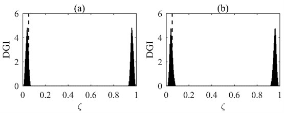
Stage I is set as the baseline to monitor damage growth from Stage I to Stages II and III. The DGIs are obtained by fusing the first 5 DGPFs and the results are presented in Fig. 4. It is seen from Fig. 4 that the DGIs peak at the dashed lines, thereby pinpointing the actual damage growth locations. It is noteworthy that the proposed method successfully locates damage growth near the boundary, where there are challenges to detecting such damage using some other methods, such as mode shape-based method, because of the interference of the boundary.
Fig. 3Experimental setup

Table 2Natural frequencies of the beam at three damage stages (Hz)
Stage | 1 | 2 | 3 | 4 | 5 | 6 | 7 |
I | 9.375 | 29.063 | 70.156 | 120.469 | 184.003 | 257.813 | 343.594 |
II | 9.375 | 29.063 | 70.156 | 120.313 | 183.594 | 257.813 | 341.563 |
III | 9.375 | 29.063 | 70.156 | 120.313 | 183.750 | 257.030 | 341.560 |
Fig. 4DGIs obtained by fusing first 5 DGPFs: a) stages I to II; b) stages I to III

5. Conclusions
Damage-induced RNFC curves in beam-like structures are derived by theoretical analysis. For monitoring damage growth, an indicator titled DGI is proposed. The effectiveness of the indicator for monitoring damage growth is confirmed by both numerical and experimental cases. The method can be used for monitoring damage growth in an efficient and cost-effective manner since natural frequencies can be conveniently measured at one accessible point of the structure.
References
-
Fan W., Qiao P. Vibration-based damage identification methods: a review and comparative study. Structural Health Monitoring-An International Journal, Vol. 10, Issue 1, 2011, p. 83-111.
-
Cao M. S., Sha G. G., Gao Y. F., Ostachowicz W. Structural damage identification using damping: a compendium of uses and features. Smart Materials and Structures, Vol. 26, Issue 4, 2017, p. 043001.
-
Bakuckas Jr J. G., Prosser W. H., Johnsont W. S. Monitoring damage growth in titanium matrix composites using acoustic emission. Journal of Composite Materials, Vol. 28, Issue 4, 1994, p. 305-328.
-
Daniel I. M., Luo J. J., Sifniotopoulos C. G., Chun H. J. Acoustic emission monitoring of fatigue damage in metals. Nondestructive Testing and Evaluation, Vol. 14, Issues 1-2, 1998, p. 71-87.
-
Maillet E., Godin N., R’Mili M., Reynaud P., Fantozzi G., Lamon J. Damage monitoring and identification in SiC/SiC minicomposites using combined acousto-ultrasonics and acoustic emission. Composites Part A: Applied Science and Manufacturing, Vol. 57, 2014, p. 8-15.
-
Chen A. S., Almond D. P., Harris B. In situ monitoring in real time of fatigue-induced damage growth in composite materials by acoustography. Composites Science and Technology, Vol. 61, Issue 16, 2001, p. 2437-2443.
-
Kumar S., Roy N., Ganguli R. Monitoring low cycle fatigue damage in turbine blade using vibration characteristics. Mechanical Systems and Signal Processing, Vol. 21, Issue 1, 2007, p. 480-501.
-
Genest M., Martinez M., Mrad N., Renaud G., Fahr A. Pulsed thermography for non-destructive evaluation and damage growth monitoring of bonded repairs. Composite Structures, Vol. 88, Issue 1, 2009, p. 112-120.
-
Kordatos E. Z., Aggelis D. G., Matikas T. E. Monitoring mechanical damage in structural materials using complimentary NDE techniques based on thermography and acoustic emission. Composites Part B: Engineering, Vol. 43, Issue 6, 2012, p. 2676-2686.
-
Diamanti K., Soutis C. Structural health monitoring techniques for aircraft composite structures. Progress in Aerospace Sciences, Vol. 46, Issue 8, 2010, p. 342-352.
-
Rathod V. T., Mahapatra D. R. Ultrasonic Lamb wave based monitoring of corrosion type of damage in plate using a circular array of piezoelectric transducers. NDT & E International, Vol. 44, Issue 7, 2011, p. 628-636.
-
Muc A., Barski M., Chwał M., Romanowicz P., Stawiarski A. Fatigue damage growth monitoring for composite structures with holes. Composite Structures, Vol. 189, 2018, p. 117-126.
-
Aidi B., Philen M. K., Case S. W. Progressive damage assessment of centrally notched composite specimens in fatigue. Composites Part A: Applied Science and Manufacturing, Vol. 74, 2015, p. 47-59.
-
Sha G., Cao M., Radzieński M., Ostachowicz W. Delamination-induced relative natural frequency change curve and its use for delamination localization in laminated composite beams. Composite Structures, 2019, https://doi.org/10.1016/j.compstruct.2019.111501.
-
Adams R. D., Cawley P., Pye C. J., Stone B. J. A vibration technique for non-destructively assessing the integrity of structures. Journal of Mechanical Engineering Science, Vol. 20, Issue 2, 1978, p. 93-100.
-
Morassi A., Rollo M. Identification of two cracks in a simply supported beam from minimal frequency measurements. Journal of Vibration and Control, Vol. 7, Issue 5, 2001, p. 729-739.
-
Zhang Z., Shankar K., Ray T., Morozov E. V., Tahtali M. Vibration-based inverse algorithms for detection of delamination in composites. Composite Structures, Vol. 102, 2013, p. 226-236.
-
Zhong S., Oyadiji S. O. Analytical predictions of natural frequencies of cracked simply supported beams with a stationary roving mass. Journal of Sound and Vibration, Vol. 311, Issues 1-2, 2008, p. 328-352.
-
Rao S. S. Vibration of Continuous Systems. Wiley, New York, 2007.
-
Sha G., Radzieński M., Cao M., Ostachowicz W. A novel method for single and multiple damage detection in beams using relative natural frequency changes. Mechanical Systems and Signal Processing, Vol. 132, 2019, p. 335-352.
-
Guo H. Y. Structural damage detection using information fusion technique. Mechanical Systems and Signal Processing, Vol. 20, Issue 5, 2006, p. 1173-1188.

