Abstract
The vibroisolation and wave properties of the lattice consisting from the beam elements and lumped masses located in the lattice nodes are studied. The finite element method is used to obtain the lattice dynamic model and its dispersion equation in analytical form. It is shown that such a lattice is a bandpass mechanical filter, and the opacity bands of the harmonic signal depending on the direction of the wave propagation is found. The limiting minimum and maximum frequencies for the harmonic signal transmission are also obtained. It is shown that the addition of discrete inclusions to the lattice increases its vibroisolation properties in low-frequency range.
Highlights
- The vibroisolation properties of beam lattices with lumped masses in the lattice nodes are studied.
- Such lattice is bandpass mechanical filter, the opacity bands for harmonic signal is found analytically.
- The dispersion equation in analytical form for lattice FEM model is received.
- The limiting minimum and maximum frequencies for the harmonic signal transmission are obtained.
- The periodic discrete inclusions improve the lattice vibroisolation properties in the low-frequency range.
1. Problem statement
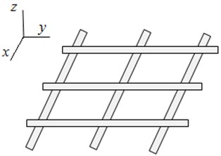
The lattice structures are often used as the vibroisolation systems. Their main advantage is the possibility of vibrations attenuation and the ability to withstand the significant static loads [1]. On Fig.1 a plane lattice with a periodic structure is presented. Due to the structure periodicity, the lattice is characterized by alternating of bandwidth and opacity band of the harmonic signal. In the opacity bands the disturbances propagate with a large attenuation, so such lattices can be considered as a band-pass mechanical filter. The wave properties for the lattice structures were theoretically and experimentally investigated in [2] and the estimates of their efficiency are given. In [3] the viboisolation properties of the periodic and dynamically self - similar lattice formed by the rod elements were studied. In this article, we study the vibroisolation and wave properties for a lattice structure consisting from the beam elements and the lumped masses located in the lattice nodes.
Fig. 1The plane lattice with a periodic structure
2. The lattices with a discrete-distributed structure
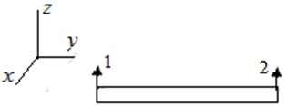
A beam lattice in which the inhomogeneities (lumped masses) are located at the discrete regular points can called as a discrete-distributed structure. Such lattices can be one-two-and three-dimensional periodic structures. At sufficiently high frequencies, the discrete inclusions will remain stationary, playing the role of a fastening for the elements with distributed parameters such as the beams. To study the oscillations and waves propagation in the lattice, it is necessary, first of all, to receive a dispersion equation. There are different ways to obtain this equation. Thus, in [2] for lattices with rod elements is proposed a method using the dynamic stiffness. Below for this purpose we use the finite element method (FEM) in analytical form, which allows to describe a fairly wide class of mechanical systems [4]. The plane beam finite element is represented on Fig. 2.
The stiffness matrixes for beam element are [4, 5]:
where J is the geometrical inertia moment for the beam, l is a finite element length, θx is rotation angle of finite element about the axis x, and analogues relations for the cross beam element in plane (z,x).
Fig. 2The plane beam finite element
3. Obtaining the dispersion equation using the finite element method
First, we explain the method of obtaining the dispersion equation using the FEM for discrete-distributed systems. For this we consider the infinity periodic chain system consisting from a beam with lumped masses located on it (Fig. 3).
Fig. 3The periodic chain system consisting from a beam with lumped masses

The equation for the natural oscillation is:
where Kij (i, j=1, 2) are the stiffness matrixes Eq. (1) for the finite elements, M is the inertia matrix for the lumped mass located on the beam.
The general view for the matrix D can be represented from Eq. (2) as:
where [D11]=K11-λM11 is a matrix describing the oscillations of a nodes, [K12] is the interaction matrix between s-th and s+1 node. Assuming the solution of the periodic structure as the traveling wave:
where μ is the wave length, ω is the oscillation frequency. Then we receive from Eqs. (3), (4) the following dispersion equation:
Such a system, as will be shown below (Section 4) is a bandpass filter [6] and it has an opacity band of the harmonic signal.
Similarly, the dispersion equations can be obtained for both plane and spatial periodic structures.
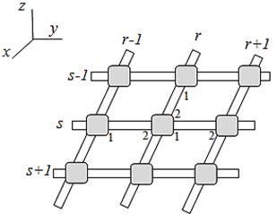
Consider now a plane lattice, consisting from the beam elements and the lumped masses, located in the lattice nodes (Fig. 4). We assume that there is only one finite element between the lattice nodes. In [4] it is shown that this is allowable in such a frequency range when the element length does not exceed ¼ of the wavelength; then the element elasticity the can be ignored.
The numbers 1, 2 near the beam element denote respectively the 1st and 2nd ends of the beam finite element. We assume that the inertial elements for the beam (Mb,Gb) are located in the lattice nodes. (M0,G0) is the mass, and the inertia moment for the lumped body. So the summary inertia matrix for lattice is diagonal:
Fig. 4a) The plane beam lattice with lumped masse (fragment); b) a subsystem with fixed ends for determining the boundary frequencies of the opacity band; c) a subsystem with free ends for determining the minimum and maximum frequencies for harmonic signal
a)

b)

c)
Presently we investigate the waves propagation in such a lattice. Now the node has a double numbering: index r for the beams located along the y axis (hereinafter these beams are called as a longitudinal for short), index s for the beams along the x axis (cross beams). The beam stiffness matrices include the following coordinates: for longitudinal beams X(z,θy), for transverse beams Y(z,θx). Thus, each node has three coordinates (z,θx,θy). So we write the motion equation for the node s, r=1,…,n:
In this equation, the Superscript 1 refers to longitudinal beams, and the index 2 refers to transverse beams, K11=(K(1)11+K(1)22)+(K(2)11+K(2)22), the inertia matrix M=diag(M,G). Considering Eq. (6) as the finite- differences equation [7], we will look for its solution as a waves product:
where μ, ν are the wave parameters in the longitudinal and transverse directions, respectively. Then from Eqs. (6), (7) we find analogously Eqs. (3), (5):
Taking into account the expressions for Kij (i, j=1, 2) Eq. (1), we obtain the following dispersion equation:
a11=48ΕJl3-24ΕJl3(chμ+chν)-Mω2,a22=8ΕJl-Gω2,a33=8ΕJl-Gω2,
where l is the finite element length between the lattice nodes, J is the geometric inertia moment for the transverse and longitudinal beams.
4. The establishment of the limiting frequencies and bandwidth of the harmonic signal
Analyzing Eq. (9), we see that the dispersion curve view depends on the wave propagation direction. Thus, when the wave propagates along the y axis (Fig. 4) the dispersion equation splits into two independent:
The first equation corresponds to the rotational oscillations around the y axis. The second equation describes the oscillations of a beam with a periodically lumped load (M,G), i.e., the lattice in this case is equivalent to a discrete-loaded beam, similar to Fig. 2, which is fairly obvious physically.
The opacity band of the harmonic signal arises as follows from Eq. (7) if cosν>1, sinν>1 when the wave parameters become purely imaginary. Therefore, the boundary of the non-transmission band can be determined from Eq. (10) at ν=π/2:
Eq. (11) defines the limiting frequencies of the opacity band: ω1, ω2. Hence it can be seen that they coincide with the frequencies of the forming subsystem with fixed ends, namely: “mass + associated beams” (Fig. 4(b)). At M0=G0=0 the dispersion Eq. (11) coincides with the equation of the finite- element beam model. As shown in [4], the opacity band of such a beam is: 98,8<ω*2<120, ω*2=ω2ml4/ΕJ, which is significantly higher than beam partial frequencies. However, when adding the lumped masses (M0,G0), its partial frequencies as follows from Eq. (11), decrease in proportion to (M0/M,G0/G) so the opacity bands can fall into the operating range. Thus, the addition of discrete inclusions to the lattice structure increases its vibroisolation properties in low –frequency range.
The minimum ω3 and the maximum ω4 frequencies are obtained from Eq. (10) at ν=0:
As follows from Eq. (8) at ν=0 we have: K11+K(2)21+K(2)12=0. This means that the roots ω3, ω4 coincide with the roots of the subsystem Fig. 4(c), describing the mass oscillations of the forming subsystem but now on the cantilever beams with free ends. By this a smaller mesh FEM is necessary.
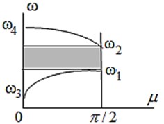
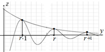
The diagram of the lattice dispersion equation, with account for Eqs. (11), (12) has the view Fig. 5 (a). The opacity band ω1<ω<ω2 is highlighted. Because in this band the wave parameter ν (or μ) becomes purely imaginary, then from Eq. (7), the wave exponentially attenuates along the structure. For example if ν=iν0, then from Eq. (7) one can see that at every moment of time Zr+1=exp(-ν0)Zr,Zr=exp(-ν0)Zr-1, that means the exponential attenuation of the wave along the structure. The oscillation frequency on time, as follows from Eq. (7), is equal to ω, but at every moment of time this exponential wave attenuation is preserved for every ω1<ω<ω2. The Fig. 5 (b) represents the exponential ratio of wave displacements along the structure at ν0=0.15 in opacity band.
Fig. 5a) The dispersion equation of the periodic lattice (the opacity band ω1<ω<ω2, is highlighted); b) the exponentially decreasing ratio of the wave displacements along the axis y in the opacity band
a)
b)
Here we see a certain analogy with the dispersion equation for the well-known in the wave’s theory problem of the diatomic molecule [8]. This is because, in both cases, the forming cell has the two degrees of freedom.
Obviously, due to the system symmetry, the opacity bands during the wave propagation along the x and y axis will be similar.
When the wave propagates at an angle of 45° (μ=ν) we obtain from Eq. (9) for a lattice with identical horizontal and transverse beams that the dispersion equation coincides with Eq. (10). In general, the location of the opacity bands depends on the direction of wave propagation. Indeed, if the transverse and longitudinal beams have the different parameters, then the opacity bands along the x and y axes would also be different.
5. Conclusions
1) A method for obtaining dispersion equations in analytical view for FEM models is proposed. It possible to analyze the oscillations and wave propagation for a wide class of mechanical systems.
2) The lattices containing the lumped inclusions, both one-dimensional (chain systems) and two-dimensional represent a bandpass mechanical filter
3) The boundary frequencies of the opacity band in lattice are defined are the frequencies of forming subsystem “the node -associated beams” with fixed ends. The limiting minimum and maximum frequencies of harmonic signal transmission are defined as the frequencies of this subsystem, but now with the free ends.
4) The addition of the lumped masses to the lattice reduces the frequency of the opacity region and improves its vibroisolation properties in low-frequency range.
References
-
Ааbel A. G. Vibroisolation of Lattice Spacers for Heavy Machines. Nauka, Moscow, 1978, (in Russian).
-
Artobolevskij I. I., Boborovnitskij J. I., Genkin M. D. Introduction in Acoustic Dynamics of Machines. Nauka, Moscow, 1979, (in Russian).
-
Banakh L. The dynamic-selfsimilar lattice as the vibroisolation systems. Vibroengineering Procedia, Vol. 25, 2019, p. 54-59.
-
Banakh Ya L., Kempner M. L. Vibrations of Mechanical Systems with Regular Structure. Springer, London, 2010.
-
Cоllatz L. Eigenwertaufgoben Mit Technishen Anwendungen. Akademische Verlagsgesselshaft Geest and Portig, Leipzig, 1963.
-
Rabinovich D. I., Trubetskov D. I. Introduction into Oscillations and Wave Theory. Nauka, Moscow, 1984, (in Russian).
-
Gallagher R. H. Finite Elements Analysis. Fundamentals. Prentice-Hall, New Jersey, 1975.
-
Pain H. J. Physics of Vibrations and Waves. John Willey and Sons, London, 1976.

