Abstract
Heterogeneous lattice structure was constructed with rhombic dodecahedron and octet-truss lattice structures. The rhombic dodecahedron lattice was bending-dominated, while octet-truss lattice was stretching-dominated. The rhombic dodecahedron lattice fabricated by selective laser melting (SLM) was compressed by a universal testing machine, which was also investigated by finite element model. Afterwards, the validated numerical model was used to study the designed heterogeneous lattice. Calculations indicates that heterogeneous lattice structures outperform the rhombic dodecahedron lattice structure. The introduction of octet-truss unit cell enhances the mechanical behavior of the heterogeneous lattice structure in terms of Young’s modulus and stress magnitude, which depends on the pattern of octet-truss cells.
Highlights
- Calculations indicates that heterogeneous lattice structures outperform the rhombic dodecahedron lattice structure.
- The introduction of octet-truss unit cell enhances the mechanical behavior of the heterogeneous lattice structure in terms of Young’s modulus and stress magnitude, which depends on the pattern of octet-truss cells.
- The rhombic dodecahedron lattice fabricated by selective laser melting (SLM) was compressed by a universal testing machine, which was also investigated by finite element model.
1. Introduction
The lattice structures attract great attention due to their extensively potential for applications, such as aerospace and transportation. The lattice structures are extensively used as energy absorber or lightweight load-bearing structure. However, it is uneconomical to fabricate a lattice structure employing traditional manufacturing processes. The advent of additive manufacturing greatly alleviates this dilemma, which makes it possible to manufacture lattice structures with complicated topology. Additively manufactured lattice structure, such as laser powder bed fusion and electron beam powder bed fusion, have been investigated with the aid of theory and various experiments.
The macro mechanical properties of lattice structures are tailored using a variety of structural design methods. The utilization of the material can be improved by taping the strut geometry, and the energy absorption is also enhanced [1, 2]. Additionally, energy absorption can also be increased by including gradient structure [3-5]. Nowadays, the crystal-inspired lattices emerge constructed by the strengthening mechanism of polycrystalline [6, 7]. The lattice structure with heterogeneous microstructure is also a promising area. Yin et al. indicate that introduction of heterogeneous structure could enhance the performance of the lattice structure [8, 9]. However, there is still a lot of uncertainty regarding the mechanical behavior of the heterogeneous lattice structures.
The proposed heterogenous lattice structure (HLS) is numerically researched to explore its static property in the current work. The finite element model is validated by the quasi-static test of rhombic dodecahedron lattice structure fabricated by selective laser melting. Furthermore, the dependence of the static properties of the designed HLS on the fraction and pattern of the octet-truss cell is also discussed.
2. Configuration and fabrication
The bending-dominated lattice always exhibits a stress-strain curves owning a flat and long stage. However, the stress level of stress-strain is low, which limits the application of the lattice structure. The heterogeneous strategy provides a promising method to overcome the weakness of lattice structure dominated by bending. Denoting the rhombic lattice structure as a soft phase, while the octet-truss lattice structure is chosen as the hard phase. Generally, the hard phase exhibits a higher stress level in stress-strain curve than that of the soft one. The unit cells of two kinds of phases marked with characteristic length and diameter are depicted in Fig. 1.
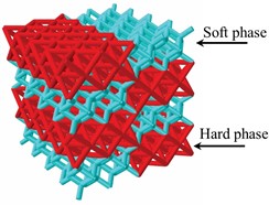
The heterogeneous lattice structure is achieved by introducing the hard phase into the soft phase, which is expected to exhibit higher stress level compared to soft phase and exhibit a flat stage compared to hard phase. The heterogeneous lattice structure with 4×4×4 unit cells is considered. A heterogeneous lattice structure is shown in Fig. 2. The impact of the pattern and number of hard phases on the energy absorption is considered here.
Fig. 1Unit cells of soft phase and hard phase
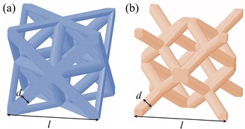
Fig. 2Illustration of a heterogeneous lattice structure
3. Quasi-static test of soft phase
The rhombic dodecahedron (RD) lattice structure with characteristic dimensions is fabricated by selective laser melting, which is suitable for the specimen with fine size. Specifically, strut length is 8 mm, while strut diameter is 1.1 mm. The quasi-static mechanical behavior of the fabricated RD lattice structure is examined on an electron universal machine, which is equipped with a force sensor of 100 kN. A thin layer of Vaseline is applied to the surfaces of sample and plates to reduce friction between them. The deformation is photographed by a digit camera at 1 frame per second, which is set in front of the sample. The recorded force divided by the initial cross-sectional area of sample is called nominal stress, while nominal strain is measured by the ratio of compressive length to the initial length.
4. Finite element analysis
The finite element analysis (FEA) is applied to effectively predict the static response of various HLSs. ABAQUS is employed to conduct the FEA. The numerical model constructed in the software is illustrated in Fig. 3. The HLS contains 64 unit cells, i.e., four unit cells along each direction. The struts of HLS are simplified as ideal, straight beam elements, which are assigned with a constant radius. Each strut is meshed into seven beam element (B31) to balance solution accuracy and calculation resources. In the quasi-static test, the sample is sandwiched between two plates. In the FEA, two analytical rigid plates are utilized to represent the plates of universal machine. As the sample is compressed by the upper plate, the degree of freedom of the lower plate is set to zero, while the strain rate of the upper plate is 0.001/s. In addition to taking into consideration the complicated contact conditions between samples and plates, the general contact is also used to take into account the self-contact of the sample. The problem of large deformation and complex contact conditions is solved explicitly, i.e., an explicit step.
Three virtual tests of the various HLSs with different patterns are numerically predicted. In the current work, the number of hard phases is 16 and 32, specifically.
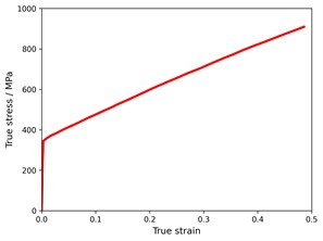
The 316L steel is adopted as the base material. The quasi-static mechanical property of the tensile specimen fabricated by selective laser melting is tested on a universal machine. Herein, the diameter and gauge of the tensile specimen are 3.34 mm and 13.36 mm, specifically. The true stress-strain of the tensile specimen is depicted as Fig. 4, which is reported by Li et al. [10]. The Young’s modulus, Poisson’s ratio, yield stress, density of the base material is 71 GPa, 0.3, 350 MPa and 7930 kg/m3 respectively. The true plastic stress-strain curve is inputted into the ABAQUS to characterize the plastic behavior of the base material. As no obvious failure occurs in the compressive test of RD lattice structure, the failure of base material is not considered in the numerical simulation.
Fig. 3Schematic of finite element model
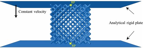
Fig. 4Quasi-static true stress-strain curve of 316L steel
5. Results and discussion
5.1. Quasi-static compressive behavior of RD
A depiction of the compressive static stress-strain curves of RD lattice structure under quasi-static compressive test are plotted in Fig. 5(a). Here, a linear, plateau, and densification stage are evident in the stress-strain curve, which is in agreement with previous literature. The RD lattice structure with stable stress stage is suitable for energy absorption. The stable stress stage results from the bending-dominated deformation mode. The deformation evolutions of the fabricated RD lattice structure under quasi-static loading are shown in Fig. 5(b). The obvious localized deformation occurs in the lattice, which forms a “X” shaped deformation band marked with blue dotted lines.
Fig. 5Results of RD lattice structure under quasi-static loading

5.2. Finite element analysis validation
Accordingly, the quasi-static experiment of the RD lattice structure is also calculated by FEA. The numerical calculation results are compared to the experimental results, which is depicted in Fig. 6(a). The yellow and blue lines are experimental results, while the green line is obtained by FEA. It can be seen that the predicted result captures the feature of experimental results, especially the linear and plateau stage. The FEA result fails to capture the onset of densification, because the beam element cannot consider the contact in detail. Additionally, the deformation evolution obtained by FEA is also compared to the experimental counterparts, as shown in Fig. 6(b). The deformation of FEA calculation is shown on the left of subplot, while the actual deformation is exhibited on the right of subplot. Obviously, the numerical simulation result matches well with the experimental one, and the localized deformation band also appears characterized a “X” shape. The localized deformation band is marked with dashdot red lines.
The validated finite element model is employed to explore the deformations of HLS with different configurations of hard phases.
Fig. 6Experimental and numerical results

Herein, several mechanical evaluation indexes are adopted to characterize the impact of hard phase number and hard phase pattern on the mechanical performance of lattice structures.
The average stress denoted as is expressed as:
where is the strain corresponding to the initial peak stress, is the densification strain, which needs to be determined with the aid of below equations:
The formula of energy absorption (EA) is:
As the density of lattice structure is apparently different, in order to eliminate the influence of relative density, the specific energy absorption (SEA) is adopted:
where is the density of HLS.
5.3. Impact of hard phase number on the mechanical performance
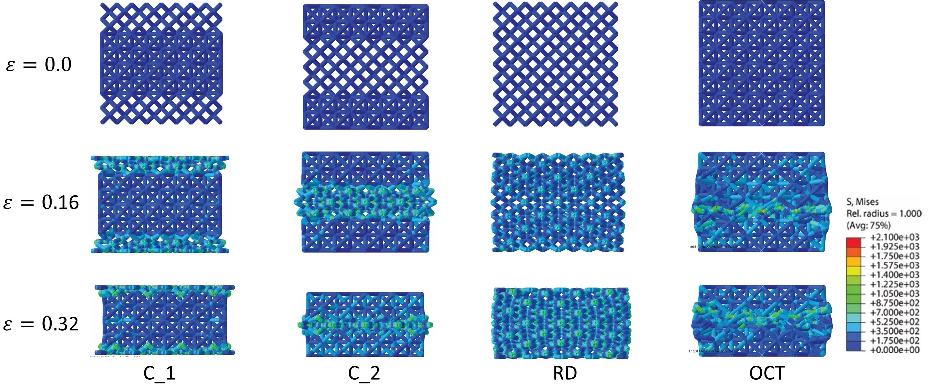
The mechanical behavior of HLSs with different number of hard phases is examined by above numerical model. The number of HLSs are 0, 32, 32 and 64 respectively. As the variation of hard phase, the specific mechanical properties are compared here, as shown in Fig. 7. It can be concluded that, the stress is elevated by the introduction of hard phase. Although the number of hard phase, i.e., C1 and C2, is identical, the mechanical properties of C1 and C2 are still different, which results from the difference of hard phase pattern.
The deformations of HLSs at different strains are demonstrated in Fig. 8. Obviously, the deformations of HLS show two stages. the deformation initiates from the soft phase, until the soft phase is densed the hard phase begins to deform. The deformation feature of lattice structures corresponds to the two plateau regions on the nominal stress-strain curve. Obviously, the localized diagonal deformation disappears, which appears in the RD lattice structure. Apparently, the hard phase changes the deformation propagation during compression.
Fig. 7Mechanical properties of HLSs
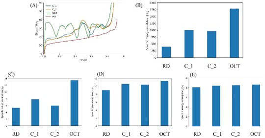
Fig. 8Deformation modes of the lattice structures
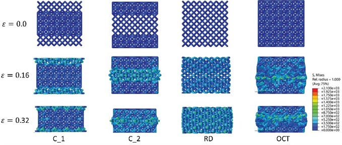
Fig. 9Various deformation modes
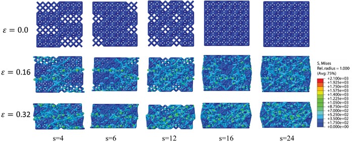
Fig. 10Various mechanical performances

5.4. Impact of hard phase pattern on the mechanical performance
The pattern of hard phase is a potential factor affecting the mechanical properties of HLS. Herein, five HLSs with 32 hard phases are designed and simulated. The number of the interface between the soft and hard phases is considered. The number of interfaces between each layer is 16, while the number of interfaces in each layer are 4, 6, 12, 16, 24 respectively. Fig. 9 exhibits that the initial deformation always appears at the soft phase. The initial deformed area shows the same pattern of deformation to that of hard phase. Similarly, no diagonal localized deformation band appears for the HLSs. Ultimately, it can be concluded that the distinct mechanism propagates specific deformation patterns, making it possible to design HLS with customized deformation patterns. The mechanical properties of HLSs with various number of interfaces are compared in Fig. 10. It can be seen that the Young’s modulus and initial peak stress increase with the increase of interface number, while the plateau stress and energy absorption corresponding to the densification strain are almost independent on the interface number. Hence, the mechanical behavior of the lattice structure can be designed by arranging the hard phase.
6. Conclusions
The heterogeneous lattice structure is proposed and designed. An analysis of the static response of the fabricated rhombic dodecahedron lattice structure is executed by conducting quasi-static compression. Accordingly, the finite element analysis is performed and validated by the experimental result. The mechanical behavior of HLSs with various number and pattern of hard phase are explored by finite element analysis. The impacts of hard phase number and hard phase pattern on the mechanical behavior are investigated numerically. Some conclusions can be drawn from above results.
The introduction of hard phase to the soft phase enhances the stress level of soft phase. HLS outperforms rhombic dodecahedron lattice structure, which also reduced the initial peak stress than that of hard phase, which is more suitable for energy absorption.
References
-
X. Cao et al., “Dynamic compressive behavior of a modified additively manufactured rhombic dodecahedron 316L stainless steel lattice structure,” Thin-Walled Structures, Vol. 148, p. 106586, Mar. 2020, https://doi.org/10.1016/j.tws.2019.106586
-
D. Qi et al., “Mechanical behaviors of SLM additive manufactured octet-truss and truncated-octahedron lattice structures with uniform and taper beams,” International Journal of Mechanical Sciences, Vol. 163, p. 105091, Nov. 2019, https://doi.org/10.1016/j.ijmecsci.2019.105091
-
D. S. J. Al-Saedi, S. H. Masood, M. Faizan-Ur-Rab, A. Alomarah, and P. Ponnusamy, “Mechanical properties and energy absorption capability of functionally graded F2BCC lattice fabricated by SLM,” Materials and Design, Vol. 144, pp. 32–44, Apr. 2018, https://doi.org/10.1016/j.matdes.2018.01.059
-
J. Mueller and K. Shea, “Stepwise graded struts for maximizing energy absorption in lattices,” Extreme Mechanics Letters, Vol. 25, pp. 7–15, Nov. 2018, https://doi.org/10.1016/j.eml.2018.10.006
-
S. Y. Choy et al., “Superior energy absorption of continuously graded microlattices by electron beam additive manufacturing,” Virtual and Physical Prototyping, Vol. 16, No. 1, pp. 14–28, Jan. 2021, https://doi.org/10.1080/17452759.2020.1868656
-
M.-S. Pham, C. Liu, I. Todd, and J. Lertthanasarn, “Damage-tolerant architected materials inspired by crystal microstructure,” Nature, Vol. 565, No. 7739, pp. 305–311, Jan. 2019, https://doi.org/10.1038/s41586-018-0850-3
-
C. Liu, J. Lertthanasarn, and M.-S. Pham, “Revealing the origins of shear band activity and boundary strengthening in polygrain-like architected materials,” arXiv:2011.02424, 2020.
-
S. Yin et al., “Strong and tough bioinspired additive-manufactured dual-phase mechanical metamaterial composites,” Journal of the Mechanics and Physics of Solids, Vol. 149, p. 104341, Apr. 2021, https://doi.org/10.1016/j.jmps.2021.104341
-
W. Guo, Y. Huang, R. O. Ritchie, and S. Yin, “Dissipative dual-phase mechanical metamaterial composites via architectural design,” Extreme Mechanics Letters, Vol. 48, p. 101442, Oct. 2021, https://doi.org/10.1016/j.eml.2021.101442
-
X. Li, L. Xiao, and W. Song, “Compressive behavior of selective laser melting printed Gyroid structures under dynamic loading,” Additive Manufacturing, Vol. 46, p. 102054, Oct. 2021, https://doi.org/10.1016/j.addma.2021.102054
About this article
The investigation was supported by the Taishan Scholars Program.
The datasets generated during and/or analyzed during the current study are available from the corresponding author on reasonable request.
The authors declare that they have no conflict of interest.
