Abstract
This paper proposes a model of three-cylinder engine excitation which includes the characteristics of the mass unbalancing. Then, a powertrain model is established to analyze the response of powertrain mounts under different balancing strategy of the mass unbalancing during idle condition. Simulation is performed based on the powertrain model to demonstrate how different balancing strategies of three-cylinder engines influence the design of powertrain mounts.
1. Introduction
Manufacturers have been encouraged to apply three-cylinder engines on passenger vehicles to answer the call for better fuel economy and efficiency as well as light weight and downsizing. Three-cylinder engines are not naturally balanced compared with four-cylinder engines [1]. Thus, numerous methods have been used to solve this problem such as counterweight, balance shaft and mass unbalancing [2]. The introduction of mass unbalancing facilitates compact design and brings about no additional noise. Since idle vibration is a major problem for three-cylinder engines, a mathematical model for idle condition analysis becomes necessary, which includes engine excitation and the dynamics model of the powertrain.
Mohammadi et al. [3] balanced a three-cylinder engine with mass unbalancing. They established a mathematical model of the excitation of three-cylinder engine, the results of which show that the introduction of mass unbalancing can allocate the proportion of rolling and yaw moments to meet different design objectives. However, their model does not consider the influence gas torque on the excitation of three-cylinder engines. Therefore, it is necessary to study the gas torque in the mathematical model.
Sirafi et al. [4] and Shangguan et al. [5] developed a 6 DOF model for modal analysis and analysis under quasi-static load. The model shows good accuracy between simulation results and tested data while the models failed to calculate system response under dynamic loads.
This work incorporates the mathematical model of three-cylinder engine with gas torque and a 6 DOFs powertrain model for dynamics analysis. Simulation based on the model is performed to evaluate the effect of variant parameters of mass unbalancing on system’s response spectrums to provide guidance for the design of powertrain mounts.
2. Powertrain model for idle vibration analysis
2.1. Mathematical model of three-cylinder engines
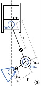
In this paper, dynamics of transverse three-cylinder engine is modeled, where the difference value of crank angle of any two cylinders is 120 degrees and the ignition interval is 240 degrees. Lumped parameter model of the one-cylinder slider-crank mechanism and one counterweight of a three-cylinder engine are shown in Fig. 1. The crank-link mechanism is simplified, where the connecting rod is simplified to a translational mass of the piston m3b and a rotational mass of the crankpin m3a. The crankpin is simplified to the mass m3a and the equivalent mass of the crank m2a. The equivalent mass of the translational part and the rotational part can be expressed as:
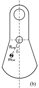
where r is the crank radius, rG2 is the distance of the crank’s center of gravity (COG) and the crankshaft main journal, l is the length of the connecting rod, lb is the distance of distance of connecting rod’s COG and piston pin, la is the distance of distance of connecting rod’s COG and crankpin and m4 is the piston mass. Then, the crank is simplified to a lumped mass mCW where RCW is crank’s COG radius and δ is the angular position of the crank. The kinematics relation of crank angle and piston position can be expressed as:
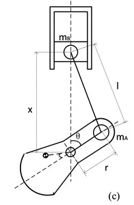
where θi is the crank angle, ω is the angular velocity of the crankshaft, φi is the phase angle of the crank and xi is position of the piston. For the convenience of numerical computing, Eq. (2) can be simplified by employing binomial expansion and acceleration of the piston can be derived:
Fig. 1a) Lumped parameter model of slider-crank mechanism, b) lumped parameter model of one counterweight, c) kinematics relation of slider-crank mechanism
When the crank-link mechanism is working, the inertia force generated →Finertia is composed of the translational and rotational inertia forces, which can be expressed as:
+ω2∑3i=1∑2j=1mCW,ijRCW,ij(-cos(θi+δij)→z-sin(θi+δij)→x),
where →x is the radial direction of crankshaft, →z is the vertical direction and →y is the axial direction of the crankshaft. The moments are divided into three types: the rolling moment Mroll about the X axis, the pitch moment Mpitch about the Y axis, and the yaw Myaw moment about the Z axis of the crankshaft.
The rolling and yaw moments are generated by the inertia moments, which can be expressed as:
Myaw=-ω2∑3i=1(mArzisinθi-∑2j=1mCW,ijRCW,ijzCW,ijsin(θi+δij)).
where zi is the axial position of the crank and zCW,ij is the axial position of the counterweight. The pitch moment is the driving torque of the engine and is generated by the inertia force of the piston. The inertia force of the piston can be decomposed into the force acting in the direction of the connecting rod S and the force acting vertically on the surface of the cylinder FN, which can be expressed as:
where λp=r/l. At the crankpin, the force FN can be decomposed into a radial force and a tangential force T. This tangential force will produce a torque proportional to it, which can be expressed as:
The expression of Mx,i can be simplified by assuming tanβ≈sinβ=λpsinθi:
Thus, pitch moment generated by inertia can be expressed as:
Pitch moment also consists of the gas torque of the engine. In order to simplify the calculation, square wave is commonly used to describe the gas torque generated in the combustion process. When the cylinder is not in the combustion process, gas torque is considered to be zero. Thus, gas torque of each cylinder Mxg,i and total gas torque Mxg in one circulation can be expressed as:
where Mgas is the average gas torque of each cylinder. The total pitch moment Mpitch is derived by summing the part generated by inertia and that by gas torque.
Finally, the mass unbalancing is modeled. The mass unbalancing is usually fixed to both ends of the crankshaft. The phase difference between the two mass and their nearest cylinder is 180 degrees.
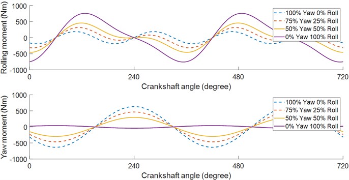
The introduction of the mass unbalancing will transform the roll moment into the yaw moment. The rolling moment and yaw moment generated by mass unbalancing can be expressed as Eq. (11) and the rolling moment and yaw moment under different balancing strategy is shown in Fig. 2.
Mb,yaw=-mbω2rbsin(θ1+π)zb1-mbω2rbsin(θ3+π)zb3.
Fig. 2Rolling moment and yaw moment under different balancing strategy
2.2. Powertrain model for idle vibration analysis
A 6 DOFs transverse powertrain model is applied to calculate the response of powertrain mounts. The Vehicle Coordinate System (VCS) is denoted with O-XYZ. A right-hand Mount Coordinate System (MCS) denoted as oi-uiviwi(i=1,2,3) is built for each mount, with its origin oi at the center of the mount. The stiffness and damping of the engine mounts in ui, vi and wi directions are kui, kvi, kwi and cui, cvi, cwi.
The displacements of COG for powertrain is defined as q=(x,y,z,θx,θy,θz) and the excitation at the COG of powertrain is defined as Q=(0,0,-mg,Mroll,Mpitch,Myaw), where m is the powertrain mass and g is gravitational acceleration. It should be noted that the inertia force of the three-cylinder engine is not dominant so that it is ignored.
2.2.1. The kinetic energy
The kinetic energy ET of the powertrain consists of translational and rotational energy of the powertrain, which can be written as:
+12Izz˙θ2z-Ixy˙θx˙θy-Iyz˙θy˙θz-Izx˙θz˙θx,
where m is the powertrain mass, Ixx, Iyy, Izz are powertrain’s moments of inertia and Ixy, Iyz, Izx are powertrain’s inertia products. Eq. (12) can be expressed in the quadratic form:
where M=[Ixx-Ixy-Izx-IxyIyy-Iyz-Izx-IyzIzz] and M is the stiffness matrix of the system.
2.2.2. The potential energy
Assuming that the potential energy change of the powertrain in the gravitational field is zero. The potential energy of the engine mount takes up all of the potential energy of the whole system. The potential energy EV of the mounting system is:
Displacement of engine mounts in MCS can be converted to displacement in VCS using the following equation:
where , and are the angle of VCS and MCS axes. Thus, stiffness matrix of the system can be derived by summing the stiffness matrixes of the powertrain mounts.
2.2.3. The dissipation energy
Because of the damping of the mounting system, energy dissipation of the whole system exists. The dissipation energy of the mounting system can be expressed as:
Similarly, the damping matrix of the system can be derived by summing the stiffness matrixes of the powertrain mounts.
2.2.4. Response of powertrain mounts
Displacement of the center of the powertrain mounts can be derived from the displacement of the powertrain COG, which can be described as:
where , and are the position of the engine mount in VCS. Thus, acceleration of the powertrain mounts can be derived by taking derivatives of , and , the spectrum of which is obtained in aid of the fast Fourier transform algorithm.
3. Analysis of simulation result
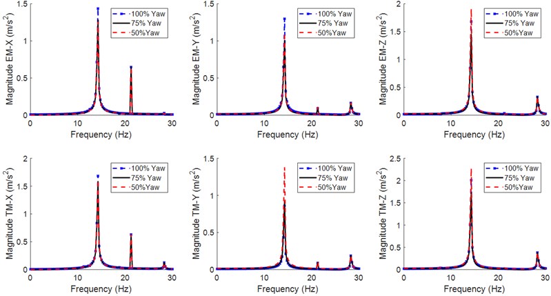
Since the load on the down strut is only axial moment, the spectrums of three-dimensional acceleration response of the engine mount (EM) and transmission mount (TM) under different balancing strategies of mass unbalancing are calculated, as demonstrated in Fig. 3.
The idle speed of the engine studied in this paper is 850 rpm which correspond to the 1st order of 14.17 Hz. Thus, it can be observed from Fig. 3 that the main excitation source of three-cylinder engine is the 1st order and the 1.5th order of the engine. Since the 1.5th order excitation is influenced only by the pitch moment, it remains unchanged under different balancing strategies. When the strategy tends to retain yaw moment of higher magnitude, the response magnitude of the 1st order of EM and TM acceleration in and direction ascends while that in direction decreases. The stiffness of EM and TM in and direction is relatively lower, so in order to avoid frequent collision of powertrain mounts on the stop block when the magnitude of yaw moment is higher, the linear space of stiffness in and direction needs to be increased in the design of powertrain mounts. On the other hand, when 75 % yaw is retained, the stiffness of direction could be decreased to attenuate rolling vibration which is sensitive for human body.
Fig. 3Spectrums of acceleration response
4. Conclusions
In this work, a 6 DOFs powertrain model including three-cylinder engine excitation is proposed to calculate the system response spectrum. It is concluded that if the balancing strategy of retaining 100 % yaw moment is applied, the linear space of stiffness in and direction needs to be increased in the design of powertrain mounts to avoid frequent collision on the stop block while if a part of yaw moment is converted to rolling moment, rolling vibration brought about should be attenuated by decreasing stiffness of direction, which can guide the design process.
References
-
Suh Kwon-Hee, Lee Yoon-Ki, YoonHi-Seak A study on the balancing of the three-cylinder engine with balance shaft. SAE Technical Paper 2000-01-0601, 2000.
-
Sharpe Robert N., David J. W., Lowndes Erik M. Determination of optimal counterweight configurations for multithrow crankshafts. SAE Technical Paper 960354, 1996.
-
Mohammadi Somaye, Ohadi Abdolreza, Keshavarz Reza Multi-objective optimization of counterweights: a substitute for the balance shaft or mass unbalancing in three-cylinder engines. SAE International Journal of Engines, Vol. 11, Issue 5, 2018, p. 557-570.
-
Sirafi Mohammad, QatuMohamad Accurate modeling for the powertrain and subframe modes. SAE Technical Paper 2003-01-1469, 2003.
-
Shangguan Wen Bin, Hou Z. Strategies and calculation methods for automotive powertrain motion control under quasi-static loads. Proceedings of the Institution of Mechanical Engineers, Part D: Journal of Automobile Engineering, Vol. 220, Issue 8, 2006, p. 1131-1138.
