Abstract
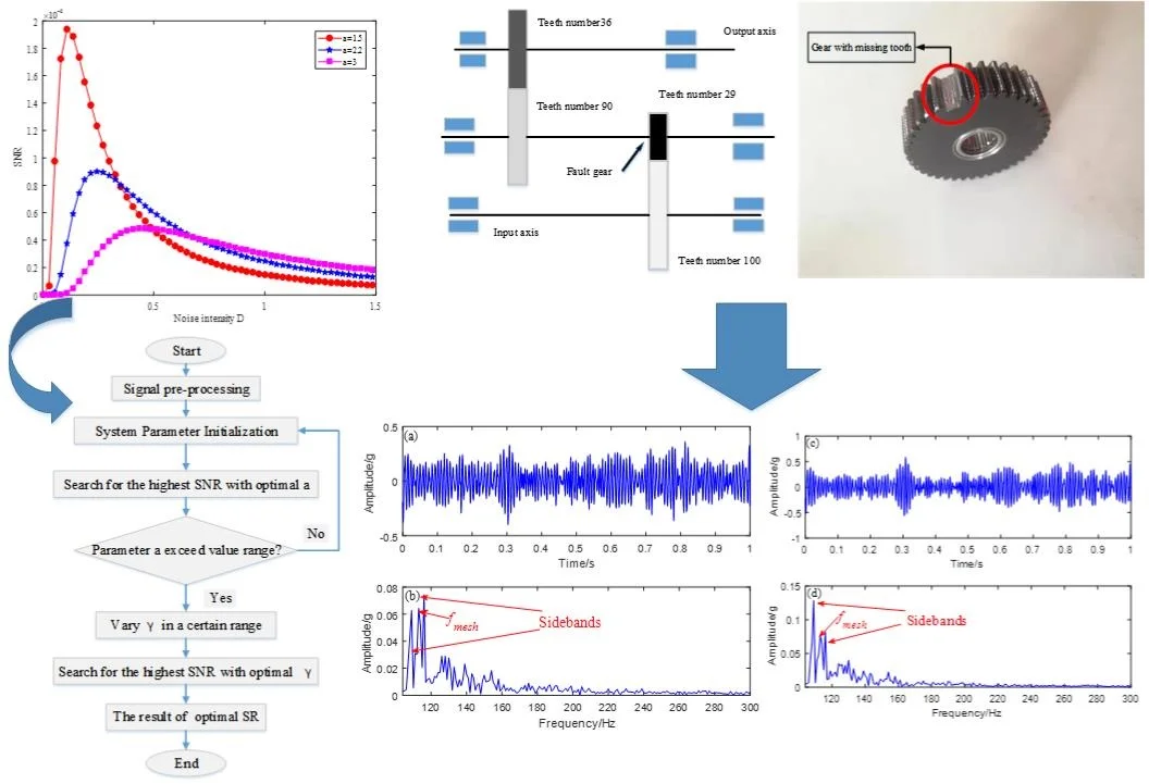
Stochastic resonance (SR) has been proved to be an effective method to extract weak-fault signals from gearboxes under strong noise. In this paper, we propose a method based on underdamped second-order SR with a new potential function. In our testing, we added an appropriate amount of Gaussian white noise to the original signal. When it matched the periodic signal and the potential function, the method showed good noise reduction ability, highlighted the fault signal and extracted fault information more effectively than the traditional SR method. The ant colony algorithm was used to optimize the potential parameters of the SR potential model and obtain the best output signal-to-noise ratio (SNR). We verified the proposed method by computer simulation and experimental verification, demonstrating that it produced better output than that of the traditional SR method.
Highlights
- A new potential model is applied to underdamped stochastic resonance
- Optimization of potential model parameters by ant colony algorithm
- The second order underdamped stochastic resonance of the new potential model is better than the traditional stochastic resonance in gear fault diagnosis
1. Introduction
Gears are widely used in mechanical equipment and play a very important role in the normal operation of the machines. If a gear fails, it can cause great damage to the surrounding mechanical equipment. Therefore, diagnosing gear faults early is an important research subject [1]. One difficulty with this is that faulty gear data collected in the field contain many noise signals. Traditional signal analysis first filters the original signal [2] and then analyzes the time domain spectrum, the frequency domain spectrum and the Hilbert transform envelope spectrum to find fault characteristics [3]. However, the fault characteristic frequency obtained by traditional signal analysis still contains large noise components, so that method’s accuracy cannot be guaranteed.
Several methods for suppressing noise have appeared to improve signal fault feature extraction (e.g. secondary sampling [4], wavelet analysis [5], and empirical mode decomposition method [6]). These methods can restrain the noise near the fault frequency to a certain extent and can identify the fault frequency, but they will also lead to the loss of some useful signals, and their effectiveness is greatly reduced at low frequency. To overcome the shortcomings of these methods, researchers have proposed stochastic resonance (SR) [7].
The concept of SR was originally proposed by Italian researchers when studying climate change. In the 1983 Schmidt experiment, scientists rediscovered the phenomenon of SR. The results of that experiment show that adding appropriate noise to a system greatly improves the output signal-to-noise ratio (SNR). The positive effects of noise in nonlinear systems have led to the recognition of the advantages of SR phenomena. Therefore, in a short period of 30 years, SR became widely used in many fields such as mechanical fault signal extraction [8], computing [9], physics [10], biology [11] and astronomy [12]. The essence of SR in signal processing is the addition of noise to the input signal. In addition, when the nonlinear system, noise, and periodic signal are optimally matched, the noise in a weak signal is greatly reduced, and the input signal response is increased.
Although SR has many advantages, the adiabatic approximation theory [13] shows that SR has the disadvantage of a small-parameter limitation, which hinders its development. To solve this problem, Leng et al. [14] proposed a rescaling frequency method, where the parameter R separates the original signal from the characteristic frequency. Wang et al. [15] introduced a scale transformation to eliminate the frequency limitation of the SR method and detected a target signal in multiple frequencies and large parameters. In [16] authors proposed a multiscale noise coordinated SR model that eliminates the small-parameter limitation of SR and successfully applied it to bearing fault diagnosis. Cui et al. [17] resampled the signal to change its frequency from high to low to meet the small-parameter limitation. The methods proposed by the above researchers have solved the small-parameter limitation problem of SR.
After solving that problem researchers began to study the effect of enhancing the output of SR. Potential models are important in analyzing SR output, and various potential functions have had a great influence on the output effect of SR. Most SR studies are based on bistable SR [18, 19]. However, nonbistable potential functions have also been applied to weak-fault diagnoses of SR. For example, Lu et al. [20] combined the Woods-Saxon potential with the Gauss potential to extract fault signals. The same authors put forward application of the FitzHugh-Nagumo potential [21] and Woods-saxon potential [22] functions in SR fault diagnosis. Zhang et al. [23] applied a pinning potential in SR, and the output effect was better than that of traditional SR. Li et al. [24] applied a multistable potential function to diagnose faults in rotating machinery. The multistable potential function can be transformed into a monostable or bistable potential function. Multistable functions can be used to detect both high and low SNR signals. Zhang et al. [25] applied a single potential well to SR, which improved the output SNR. These potential functions were used to replace the traditional bistable potential and to extract weak fault signals from bearings.
In our research, we applied a new potential function to a second-order underdamped SR. The potential function in the proposed SR method contains only one parameter. When we optimized the parameters, we found only the maximum of the potential parameters. Compared with traditional SR method, the optimal matching of multiple parameters was simpler. The optimal output is obtained by combining SR with an ant colony algorithm [26], and the proposed second-order underdamped SR had more advantages than the traditional SR. Because of its good denoising performance, the proposed SR method could be applied to gear-fault diagnosis, and the output effect and diagnostic efficiency would be better than those of the traditional SR method.
In this study, the new potential function was combined with the second-order underdamped SR and to early gearbox fault diagnosis. The ant colony algorithm was used to find the optimal parameters in the SNR. To verify the effectiveness of the proposed scheme, we compared the new method with the traditional bistable SR denoising, which proved the new method’s advantages.
This paper is arranged as follows: Section 2 introduces the new potential function and derives the SNR. Section 3 describes the diagnostic strategy. Section 4 describes the computer simulation. Sections 5 and 6 describe the experimental verification, and Section 7 summarizes the article and presents the conclusions.
2. Underdamped SR method
The traditional first-order SR is equivalent to primary filtering, and the second-order underdamped SR is equivalent to secondary filtering, which has a better filtering effect. Therefore, we proposed the underdamped second-order new potential function SR model and applied it to early weak-fault diagnosis of gearboxes.
2.1. Underdamped second-order SR model
The underdamped second-order new potential function SR model is given by:
where N=√2Dε(t) is noise, D is noise intensity, ε(t) is zero-mean and unit-variance Gaussian white noise and S(t)=Acos(Ωt+φ) is the periodic signal, where A is the periodic signal amplitude, Ω is the driving frequency, and φ is the phase.
To better improve the SR output, we introduce a new potential function. The nonlinear potential function expression is:
where a is the parameter of the potential function and x is the input of the system.
Fig. 1Two-dimensional potential function graph
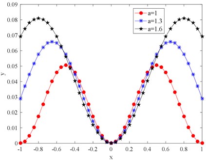
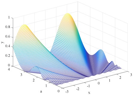
As shown in Fig. 2, the shape of the potential function changes with the change of parameter a, When parameter a changes from 1 to 1.6, the potential wall of the potential function becomes steeper, and it is more difficult for the particles to transit between potential wells. The larger the parameter a, the higher the potential barrier the wider the potential width, and the more difficult it is for the particles to transit between the two potential barriers. The above analysis indicates that the structure of the potential model can be changed by adjusting the potential parameter a.
Fig. 2Three-dimensional potential function graph
2.2. Second-order SR model based on a new potential function
After introducing the new potential function, we obtained the new underdamped second-order SR model by substituting the new potential function into the above formulas as follows.
Second-order SR model:
Let A=0, D=0, and dxdt=0 then d2xdt2=0 gives sin2πax=0.Then we can get the three singularities (x+y+)=(a20), (x0y0)=(00) and (x-y-)=(-a20) in the interval (-ππ). Linearizing the Eq. (3) at singularity (x±y±) gives (01-cos2πax0), the corresponding singular value is β1,2=±1. Linearizing the Eq. (3) at singular point (x0,y0) obtains the linearized matrix (01-10). Therefore, we can get the singular value λ1,2=±√-1.
ρ(x,y,t) is the probability density function of the system Eq. (3) at time t and dxdt=y, and then the Fokker-Planck equation for the probability density distribution is as follows [27]:
The quasi-steady-state distribution function ρst(x,y,t) of Eq. (3) obtained from adiabatic approximation theory, which expressed as [13, 28]:
where ˉN is the normalization constant, and the generalized potential well function is developed by small-parameter expansions [28]:
The probability transfer rate of the particles between the two potential wells can then be expressed as [28]:
Substituting Eq. (6) into Eq. (7), we can get:
Expansion by using the Taylor formula gives:
where R0=√β1β22π√-λ1λ2exp(-a22π2D).
The system power spectrum is then expressed as follows [28]:
where S1(ω) and S2(ω) are the power spectra of the signal and noise, respectively. To simplify the S1(ω) and S2(ω) representations [29], we write:
Bring Eqs. (9, 11, 12, 13) into Eq. (14) to get the Eq. (15):
Fig. 3Underdamped SR output SNR diagram
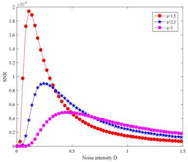
According to the SNR calculated by Eq. (14), the parameters are set as follows: A= 0.005, Ω= 0.002, a= 1.5, 2.2, 3, and D=[0.01, 4] to get the SNR change map. Fig. 3 shows that the SNR is very small when the noise component is very small and increases rapidly as the noise component increases gradually the smaller the parameter a, the faster the SNR increases. When the noise increases to a certain value, the SNR reaches its peak value, starts to decrease, and finally stabilizes to a certain value. When the noise, periodic signal, and the nonlinear system are favorably matched, the output of the system will be optimal and the energy of the noise signal can be transformed into fault signal energy to the greatest extent. When the noise component is reduced, the fault characteristic frequency can be identified more clearly.
3. Underdamped SR weak-fault diagnosis strategy
In Section 2, the potential model was discussed and the SNR derivation and the SNR output under various parameters were studied. In this section, we propose a weak fault diagnosis strategy based on the new potential model SR method.
The essence of the SR phenomenon is to convert noise energy into fault signal energy, to highlight the fault characteristics while reducing the noise, and then to extract the early faults. In the SR system, the periodic force and the noise force are constant, and the output of the system depends on the shape of the potential model. Different potential models have different effects on the system output, and the potential model is adjusted mainly by adjusting the potential parameters. Under normal circumstances, the particles do not return to the original potential well because the potential well is too wide. However, when the potential well is too narrow, the particles are pushed backward by the force when the particle does not reach the expected position, and the optimal output is not achieved. Meanwhile, when the potential is too steep, the particles recover at a speed greater than that of the periodic oscillation under the rebound of the potential wall, and when the potential wall slope is too gradual, the force cannot provide acceleration to the particles to enhance the periodic oscillation. Only when the potential structure is optimally matched to the periodic force can the system output be enhanced and the system reaches its optimal output. We used the SNR to evaluate the system output. The SNR is defined as follows:
where Ad is the magnitude of the drive frequency and An is the magnitude of the strongest interference frequency. A higher SNR creates a better distinction between signal and noise, and the fault signature frequency can be better identified. As shown in Fig. 4 the fault diagnosis strategy based on the new potential function is as follows:
1) Signal pre-processing: First filter the original signal, then demodulate the filtered signal and extract its driving frequency by calculating the envelope spectrum signal.
2) Parameter initialization: Fix the underdamping factor γ and set the optimization range of parameter a.
3) Optimization of parameter a: Calculate the power spectrum of the output waveform and the output SNR according to the fourth-order Runge-Kutta formula and Eq. (16), respectively. Then search the largest SNR in the search range of parameter a to obtain the best parameter corresponding to the peak. Finally, check whether its value has reached the edge of the search range. If so, return to step 2 and expand your search. Otherwise, continue to the next step.
4) Optimize the damping factor γ: Using the temporarily optimized parameter a, change the value of γ within a reasonable range, and calculate the output SNR of different γ values. Search for the highest SNR and corresponding γ value.
5) Signal post-processing: Obtain the best output waveform with optimized parameters as the weak signal detected. In this way, periodic signals can be successfully detected and the noise is significantly reduced. Calculate its power spectrum to identify the drive frequency.
4. Simulation
After we designed the strategy of underdamped SR fault diagnosis, we performed a simulation validation by simulating the input signal, which was s(t)=Asin(2πft)+√2Dε(t), where A= 1 was the signal amplitude, f= 1 kHz was the control pulse, ε(t) was the zero-mean Gaussian white noise unit variance, and D was the noise intensity. we took 5000 sampling points.
Fig. 4SR fault diagnosis strategy diagram
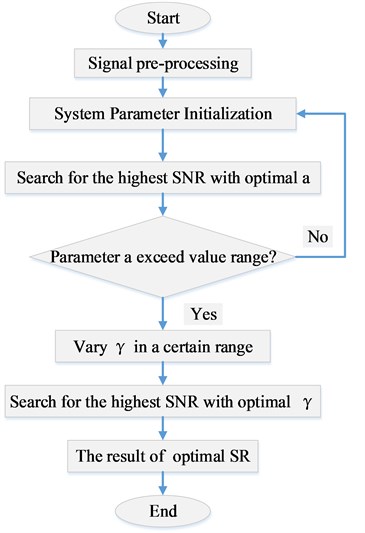
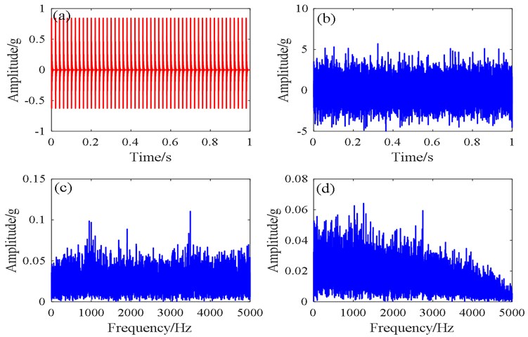
Fig. 5 shows the time domain and frequency domain plots of the simulated signal. Because of severe noise interference, the fault signature frequency could not be obtained from the time domain diagram. The presence of the characteristic frequency and the octave component can be seen in the envelope spectrum in Fig. 5(d) of the Hilbert transform, but there was still serious noise interference.
Fig. 5Time domain and frequency domain plots of the simulated signal: a) clean signal, b) noisy signal, c) spectrum, d) spectrum of envelope signal
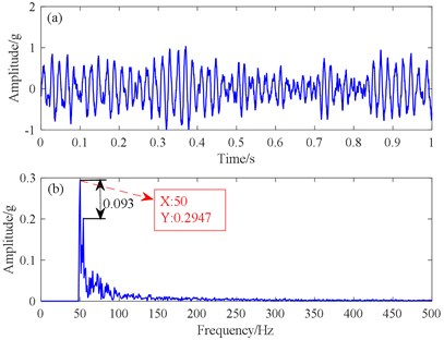
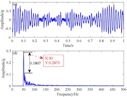
To compare the traditional SR method with the new potential function SR method. we first introduced the pre-processed signal into the traditional SR, the fault features were clearly identified in the spectrogram Fig. 6(b). The target signal detection was greatly improved, but there was still some noise frequency interference. Therefore, we proposed the signal using the new SR method, and the obtained result in Fig. 6(d) shows a lower noise level than that resulting from the conventional signal. The difference between the peak of the fault characteristic and the peak of the noise was greater than that of the conventional SR, and there was better fault recognition.
Fig. 6Simulated signals comparing the results from the traditional SR and the proposed SR methods: a) traditional SR time domain, b) traditional SR spectrum, c) proposed potential function SR time domain, d) proposed potential function SR spectrum
5. Experimental verification
To verify the effectiveness of the proposed method, we used an edentulous gear in a gearbox. The experimental data came from a comprehensive test bench for power transmission fault diagnosis (see in Fig. 8). The test bench consisted of a drive motor, a coupling, a torque sensor, a secondary speed reducing planetary shaft gearbox, and a secondary speed increasing parallel shaft gearbox. Accelerometers were mounted on the vertical radial, horizontal radial, and axial test points of the countershaft end caps of the parallel shaft gearbox, with a modulus of 1.5, comprised two pairs of gears (Fig. 7). The numbers of teeth on the gears were Z1= 100, Z2= 29, Z3= 90, and Z4= 36. The experimental setting sampling frequency was fs= 5120 Hz, and the motor speed was 1840 r/min. Data acquisition and analysis were done on the gears of the parallel shaft gearbox, such as missing teeth and wear, at a reduction ratio of 4.572:1.
Fig. 7Schematic of parallel-axle gears in the parallel shaft gearbox
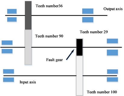
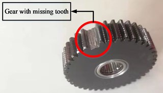
Fig. 8Fault diagnosis test-bed for gearbox tests
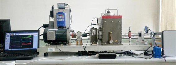
Table 1Significant parameters of the parallel shaft gearbox
Shaft I frequency (Hz) | Shaft II frequency (Hz) | Shaft III frequency (Hz) | Gear I meshing frequency (Hz) | Gear III meshing frequency (Hz) |
1.136 | 3.91 | 9.791 | 113.58 | 352.49 |
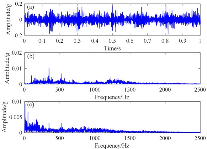
On the basis of vibration theory, for the parallel shaft gearbox the fault characteristic frequency of the pinion of the intermediate shaft was 3.91 Hz, and the meshing frequency was 113.58 Hz. The time domain, frequency spectrum, and envelope spectrum of the collected missing tooth data are shown in Fig. 9. Because of the very large noise component of the time domain signal, only a scattered effect was found, which indicates that the noise concealed the tiny fault features. There were obvious peaks in the spectrum and the spectrum of envelope signals, but they were not related to the fault feature frequency, so the fault information could not be identified.
Fig. 9Collected missing tooth data from the parallel shaft gearbox: a) time domain waveform, b) spectrogram, c) spectrum of envelope signal
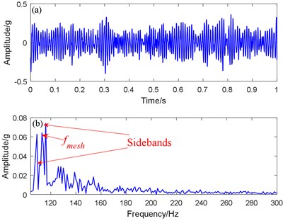
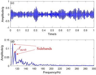
To identify fault information, we compared the proposed SR method with the bistable SR method. For this, we dealt with the fault data from the planetary shaft gearbox by using the traditional SR method and the proposed SR method respectively. Fig. 10(d) shows that the peaks of the meshing frequency and sideband frequencies are clearly higher than the peaks of the surrounding noise frequency. The differences between the meshing and sideband frequencies were 3.65 and 3.72 Hz respectively, which was close to the 3.91 Hz rotating frequency of Axis II, so the fault feature was extracted successfully. The best output result figures of fault feature frequency extracted by the traditional SR method are shown in Fig. 10(a) and 10(b). The differences between the meshing and sideband frequencies were 3.45 and 3.52 Hz respectively, which was also close to the theoretical frequency of 3.91 Hz, so the fault was successfully identified. However, the peak value of the spectrum in the meshing and sideband frequencies, and the output SNR were markedly lower than those of the proposed SR method, Therefore, the proposed SR method was successfully verified for a parallel shaft gearbox fault. Compared with the traditional bistable SR method, its output effect was larger in amplitude, higher in recognition, and better in noise suppression.
Fig. 10Traditional SR and proposed SR methods for addressing a missing tooth signal: a) Traditional SR time domain waveform, b) Traditional SR spectrogram, c) Proposed SR time domain waveform, d) Proposed SR spectrogram
6. Engineering verification
For experimental verification, we took experimental data from taken from a rolling mill gearbox (Fig. 12). After the gearbox was found to be abnormally vibrating, the alarm system did not sound. To perform better equipment maintenance and early fault diagnosis, acceleration sensors were arranged vertically, horizontally, and radially on the gearbox input shaft for data acquisition. The sampling frequency was 2560 Hz during data acquisition, for data analysis we used 2048 sampling points, and the motor speed was approximately 1300 r/min. The weekly frequencies and meshing frequencies were calculated as shown in the Table 2.
Fig. 11Schematic diagram of the rolling mill gearbox
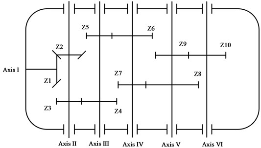
Table 2Weekly frequencies and meshing frequencies of the experimental planetary shaft gearbox
Axis | Gear ratio | Revolutions (r/min) | Rotating frequency (Hz) | Gear meshing frequency (Hz) |
1 | – | 1300 | 21.67 | – |
2 | 33/38 | 1129 | 18.82 | 717 |
3 | 42/89 | 533 | 8.89 | 790 |
4 | 21/74 | 151 | 2.52 | 186 |
5 | 24/85 | 43 | 0.72 | 61 |
6 | 38/38 | 43 | 0.72 | 27 |
Fig. 12Fault gear of the rolling mill
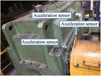
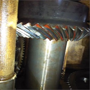
Fig. 13Signal diagrams generated by engineering data: a) time domain signal, b) spectrogram, c) spectrum of envelope signal
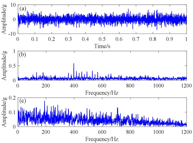
Fig. 13 shows the original signal diagrams generated by engineering data, Fig. 13(a) shows the time domain signal, which exhibits a very weak equal-interval effect, making it difficult to determine the period of the effect from the signal. The spectrum map in Fig. 13(b) appears to have no fault characteristics. In the Fig. 13(c), the envelope spectrum, there is much noise interference, so the fault signature frequency cannot be identified.
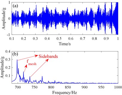
To compare fault feature extractions performance, we used the traditional bistable SR method and proposed SR method to process the signal. Fig. 14(a) shows the time domain signal of the traditional SR method, and Fig. 14(b) shows its spectrum diagram. The time domain signal is very messy, and no useful information can be found. In the spectrum, we can clearly see the mesh peak value, which corresponds to the frequency of 717 Hz mesh frequency, and the sideband frequency, The difference between them is approximately equal to the 18.82 Hz rotation frequency of Axis II, so the fault was identified successfully.
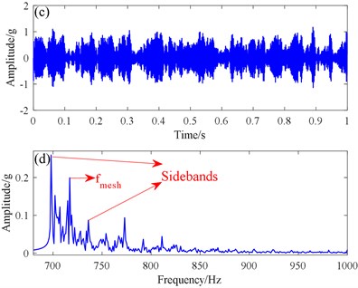
To illustrate the effectiveness of the proposed SR method, we use it to process fault signals from the planetary gearbox. We successfully found the meshing frequency and its sideband frequency in the spectrum Fig. 14(c) and Fig. 14(d). The differences between meshing and sideband frequencies were 18.5 and 18.6 Hz, which are very close to the Axis II rotating frequency of 18.82 Hz. Also, the peak values of the meshing and sideband frequencies were higher than those of the traditional SR method. The output SNR is 42.3 dB, which was also higher than that of the traditional SR. Therefore, with strong background noise, the proposed method can more effectively extract the fault features extraction of a planetary shaft gearbox.
Fig. 14Traditional SR method and proposed SR methods: a) time domain signal, b) spectrogram from the traditional SR method, c) time domain signal, d) spectrogram from the proposed SR method
7. Conclusions
In this paper, we proposed a new potential function SR method for early gear fault detection. Based on the basis of simulation and experimental verification results, we draw the following conclusions:
1) The proposed potential function in the paper has only one potential parameter, and the parameter optimization is simpler than that of the traditional SR method. The output SNR can be changed by changing the parameter value, and the parameters are optimized by an ant colony algorithm to obtain the optimal parameters.
2) The proposed method employs a second-order underdamped SR, and the second-order one-order SR method filters better. The noise energy is converted to the fault signal energy, and the fault feature is discemible, while the noise is suppressed.
3) The advantages of the proposed method were proved in the simulation and experimental verification. Its output effect was clearer than that of the traditional bistable SR method. The proposed method can effectively extract the fault characteristic information of a gear operating under strong background noise, and be used to compare the signal analysis method and the filtering.
References
-
Zhang J., Feng Z. P., Chu F. L. Fault diagnosis of gears based on time-wavelet energy spectrum. Journal of Vibration and Shock, Vol. 30, 2011, p. 157-161.
-
Yang D. D., Zhao Y. K. Comparison of wave filtering by wavelet transform and EMD in fault diagnosis of rolling bearings. Mathematics in Practice and Theory, Vol. 41, 2011, p. 121-127.
-
Xun J., Yan S. Z. A revised Hilbert-Huang transformation based on the neural networks and its application in vibration signal analysis of a deployable structure. Mechanical Systems and Signal Processing, Vol. 22, 2008, p. 1705-1723.
-
Rashidzadeh R., Ahmadi M., Miller W. C. On-chip measurement of waveforms in mixed-signal circuits using a segmented subsampling technique. Analog Integrated Circuits and Signal Processing, Vol. 50, 2007, p. 105-113.
-
Peter Tse, Yang W., Tam H. Machine fault diagnosis through an effective exact wavelet analysis. Journal of Sound and Vibration, Vol. 227, 2004, p. 1005-1024.
-
Zhang J. W., Zhu N. H., Yang L., et al. A fault diagnosis approach for broken rotor bars based on EMD and envelope analysis. Journal of China University of Mining and Technology, Vol. 17, 2007, p. 205-209.
-
Gammaitoni L., Peter H., Peter J., et al. Stochastic resonance. Reviews of Modern Physics, Vol. 70, 1998, p. 223-287.
-
Collacott R. A. Mechanical Fault Diagnosis and Condition Monitoring. Springer, 1977.
-
Sakumura Y., Aihara K. Stochastic resonance and coincidence detection in single neurons. Neural Processing Letters, Vol. 16, 2002, p. 235-242.
-
Gang H. Stochastic resonance without external periodic force. Physical Review Letters, Vol. 71, Issue 6, 1993, p. 807-810.
-
Dees N. D., Bahar S., Moss F. Stochastic resonance and the evolution of Daphnia foraging strategy. Physical Biology, Vol. 5, 2008, p. 044001.
-
Pyragas K., Svirskas K. Stochastic resonance in the flow of test particles in the field of a Kerr black hole. Gravitation and Cosmology, Vol. 15, 2009, p. 247-249.
-
Thiele M., Gross E. K., Kümmel S. Adiabatic approximation in nonperturbative time-dependent density-functional theory. Physical Review Letters, Vol. 100, 2008, p. 153004.
-
Leng Y. G., Leng Y. S., Wang T. Y. Numerical analysis and engineering application of large parameter SR. Journal of Sound and Vibration, Vol. 292, 2006, p. 788-801.
-
Wang G. F., Zhang H. R., Zhang F. Q. Scale transformation for detecting weak periodic signal of stochastic resonance. Journal of Guilin University of Electronic Technology, 2010, p. 441-444.
-
He Q. B., Wang J., Liu Y. B., et al. Bearing defect diagnosis by stochastic resonance with parameter tuning. Prognostics and System Health Managment Conference, 2011.
-
Cui Y., Zhao J., Guo T., et al. Bearing fault diagnosis based on scale-transformation SR. Journal of Beijing Information Science and Technology University, Vol. 8916, 2015, p. 36.
-
Fauve S., Heslot F. Stochastic resonance in a bistable system. Physics Letters A, Vol. 97, 1983, p. 5-7.
-
Xu B. H., Duan F. B., Bao R. H. Stochastic resonance with tuning system parameters: the application of bistable systems in signal processing. Chaos, Solitons and Fractals, Vol. 13, 2002, p. 633-644.
-
Zhang H. B., He Q. B., Lu S. L. Stochastic resonance with a Joint Woods-Saxon and Gaussian Potential for bearing fault diagnosis. Mathematical Problems in Engineering, Vol. 2014, 2014, p. 315901.
-
López C., Zhong W., Lu S. L. Stochastic resonance in an underdamped system with FitzHug-Nagumo potential for weak signal detection. Journal of Sound and Vibration, Vol. 411, 2017, p. 34-46.
-
Lu S. L., He Q. B., Kong F. R. Stochastic resonance with Woods-Saxon potential for rolling element bearing fault diagnosis. Mechanical Systems and Signal Processing, Vol. 45, 2014, p. 488-503.
-
Zhang H. B., He Q. B., et al. Stochastic resonance in an underdamped system with pinning potential for weak signal detection. Sensors, Vol. 15, Issue 9, 2015, p. 21169-21195.
-
Li J. M., Chen X. F., He Z. J. Multi-stable SR and its application research on mechanical fault diagnosis. Journal of Sound and Vibration, Vol. 332, 2013, p. 5999-6015.
-
Zhang W., Xiang B. R. A new single-well potential SR algorithm to detect the weak signal. Talanta, Vol. 70, 2006, p. 267-271.
-
Duan H. B., D. B. W., Zhu J. Q. Development on ant colony algorithm theory and its application. Control and Decision, Vol. 19, 2004, p. 1321-1320.
-
Hu G., Nicolis G., Nicolis C. Periodically forced Fokker-Planck equation and stochastic resonance. Physical Review A, Vol. 42, 1990, p. 2030-2041.
-
Hu G. Stochastic Forces and Nonlinear Systems. Shanghai Scientific and Technological Education publishing House, Shang Hai, China, 1994.
-
Li J., Chen X., Du Z. A new noise-controlled second-order enhanced stochastic resonance method with its application in wind turbine drivetrain fault diagnosis. Renewable Energy, Vol. 60, 2013, p. 7-19.

