Abstract
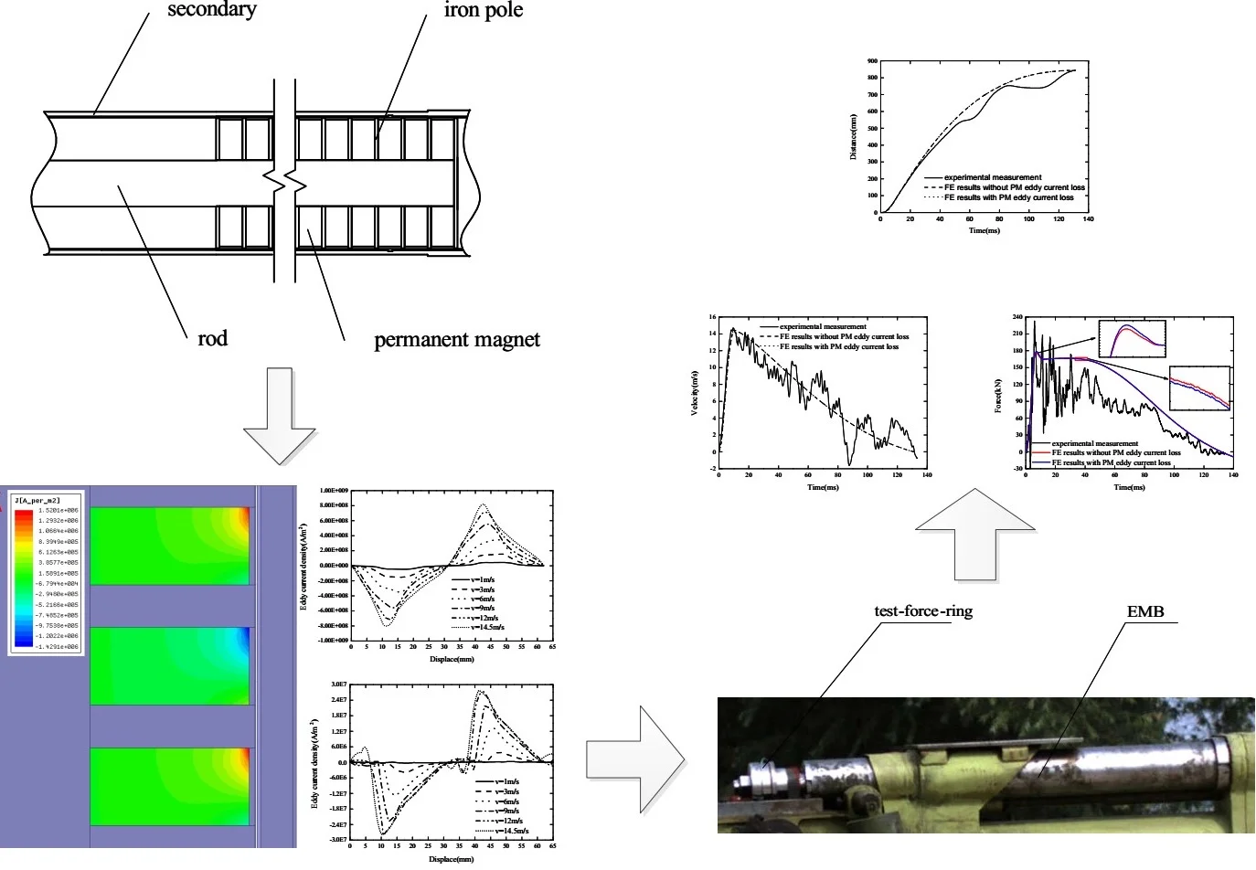
The intensive impact load will generate a huge acceleration in the primary part of the Electromagnetic buffers (EMBs), resulting in an instantaneous increase in the eddy current loss of the permanent magnet (PM). In this paper, the PM eddy current loss is taken into account in the electromagnetic buffering under intensive impact load. The reason why the eddy current damping force differs between two different buffer stages is analyzed. The experimental results signify that the model considering the PM eddy current loss is more accurate.
Highlights
- Electromagnetic damping under intensive impact load
- Permanent magnet eddy current loss under intensive impact load
- The difference between eddy current loss of inner and outer tube
1. Introduction
Electromagnetic buffers (EMBs) are used in a range of technological applications such as braking systems [1-4], structural vibration suppression [5, 6] since the advantage of no additional stiffness and no friction [5, 7].
The time-varying eddy currents are induced in the conductor tube by the relative motion between the secondary part and the permanent magnet (PM). According to Lenz’s law, the eddy currents induce another magnetic field with opposite polarity of the primary external magnetic field, thereby causing repulsive forces, i.e., damping forces, which tends to stop the buffer (shown in Fig. 1).
The damping mechanism via eddy currents has been investigated by many researchers. Ebrahimi et al. introduced the analytical model considering the skin effect and heat transfer of a new cylindrical linear eddy current buffer for a vehicle suspension system verified by low-velocity experiments [1-4]. Irazu et al analyzed a contactless eddy current damper, which consists of applying steady state magnetic fields to conductive structures in order to dampen their vibration [5]. Butt et al proposes a two-degree-of-freedom apparatus of machining vibration attenuation of compliant part by means of a non-contact damping [6].
The research on EMB mainly focuses on the buffer mechanism and damping characteristics under low-velocity and low-load, therefore, there is less research considering the PM eddy current loss, which cannot be ignored under intensive impact load.
The eddy current produces a demagnetization magnetic field on the PM, at the same time a high-frequency eddy current is generated in the PM with applied intensive impact load. In this paper, a cylindrical linear EMB is introduced to study the damping characteristics of PM eddy current loss under intensive impact load.
2. Construction and principle of EMB
As illustrated in Fig. 1, the studied cylindrical linear EMB mainly consists of two parts: (1) the primary part, which consists of a moving rod combined with a sequence of ring-shaped, axially magnetized PMs separated by pure iron poles, and (2) the secondary part, which consists of an outer tube and an inner tube.
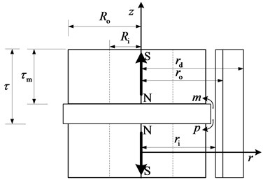
Fig. 2 exhibits the layout of the primary part and the secondary part of the EMB, which are oriented with magnetic poles of the same polarity facing each other to increase the amount of magnetic flux entering the secondary. , , , , , , are the thickness of the PM; the pole pitch; the internal radius of the inner tube; the external radius of the inner tube (the internal radius of the outer tube), the external radius of the EMB, the internal radius of the PM, the external radius of the PM, respectively.
The cylindrical EMB can reach high velocity in a short time under the intensive impact load, which causes the eddy current distribution to be affected by the boundary effect, demagnetization effect and skin effect.
Fig. 1Schema of the studied EMB
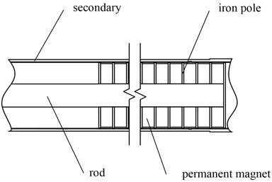
Fig. 2Configuration of the EMB
2.1. Edge effect
The eddy currents generated by the original magnetic field in the infinite inner tube and outer tube are obtained by:
where , and are the EMB velocity; the magnetic field in the conductor; the inner tube and outer tube conductivity, respectively. It can be seen from Eq. (1) that the eddy current density in the infinite inner and outer cylinders of length is not 0. since the outer tube is ferromagnetic material with non-negligible conductivity, there is still induced eddy currents, the edge effect has a weak influence on the eddy current density of the inner tube. the radial component of eddy current density of the inner tube is approximately uniform.
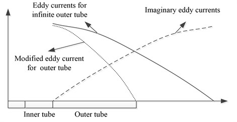
However, the effect of the edge effect on the outer tube cannot be ignored, as demonstrated in Fig. 3. The eddy current density at the outer tube edge is 0, which is considered by introducing mirror current. Therefore, the eddy current density at the outer tube can be expressed as:
where and are the eddy current density for infinite outer tube and the imaginary eddy current, respectively.
The damping force generated by the motional electromotive force at the inner tube is obtained by:
where and are the component of velocity and the penetration depth. However, the damping force generated by the motional electromotive force at the outer tube can be obtained by the mirror current as follows:
The eddy current damping force of the electromagnetic buffer can be expressed as:
Fig. 3Eddy currents of the inner tube and outer tube
2.2. Demagnetization effect
When the primary motion occurs, the eddy current density varies with the velocity of the EMB driven by intensive impact load. The time-varying eddy current magnetic field interacts with the original magnetic field, resulting in the distortion of magnetic lines. The eddy current magnetic induction can be obtained by Ampere circuital theorem as follows:
where , and are the radial lengths of the air-gap, and the cross-sectional area of the eddy current region generated in the inner tube and outer tube, respectively.
2.3. Skin effect
The fundamental frequency of the induced currents in the secondary is limited by the buffer velocity. The penetration depth is defined as the depth below the conductor surface at which the current density decreases to 1/ of the current density at the surface, which is obtained from:
where is the relative permeability of the conductor.
3. FE result and impact test
Ansoft Maxwell, a mature Finite element (FE) software for electromagnetic fields, is used to study the PM eddy current loss under intensive impact load. The solution of cylindrical about under Maxwell 2D is selected for electromagnetic transient analysis. The simulated intensive impact load is imported to the two-dimensional axial-symmetry FE model (Fig. 4) by using the built-in functions. The PM conductivity is the common value of NdFeB 625000 s/m. The FE models of considering the PM eddy current loss and without it are compared. As illustrated in Fig. 4, the FE model calculate the eddy current distribution of adjacent permanent magnets without showing the eddy current of the conductor tube and iron pole when the EMB velocity is 6 m/s.
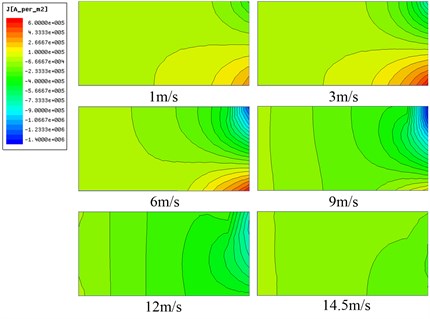
Fig. 5 is a view showing the eddy current distribution of the permanent magnet with the PM eddy current loss. The maximum value of the eddy current loss appears between 6 m/s and 9 m/s instead of the maximum velocity since the eddy current loss is affected by the change rate of the secondary field. The EMB subjected to the impact load has the smallest acceleration at the maximum velocity and thus the loss eddy current is negligible. The eddy current of the PM lower side is one order of magnitude above the upper side, which is consistent with the local demagnetization position of the PM caused by the secondary eddy current field.
Fig. 4Local diagram of EMB FE model
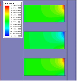
Fig. 5Eddy current distribution of PM
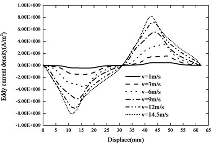
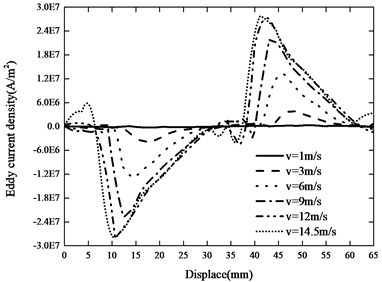
The axial current of two pole lengths of the inner and outer tube is shown in Fig. 6. The eddy current of the inner tube is uniform with the velocity less than 3 m/s. As the velocity increases, the eddy current decreases on one side of the inner tube, and the eddy current increases on the other side, as does the outer tube.
Fig. 6The axial current and a) the inner, b) outer tube
a)
b)
As demonstrated in Fig. 7, a manufactured prototype EMB system has been tested under the intensive impact load, which is consistent with the impact load of the FE model shown in Fig. 8, under room temperature.
Fig. 7Fabricated prototype for proof of concept
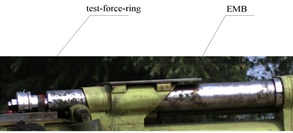
Fig. 8Intensive impact load
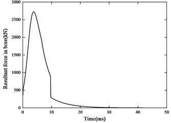
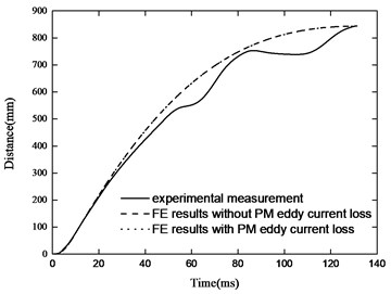
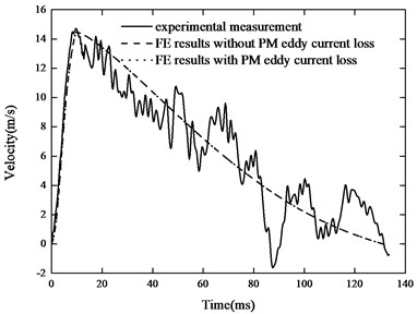
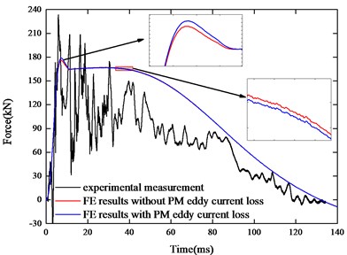
Through the comparison of FE results, we find the damping force with the PM eddy current loss is greater than that without the PM eddy current loss when the eddy current damping force is smaller than the intensive impact load. The peak of the damping force has a difference of 3 kN. Since the PM eddy current loss in the acceleration phase is much larger than that in the high speed phase, the PM eddy current magnetic field is more likely to hinder the increase of the secondary eddy current magnetic field. Thereby, the secondary eddy current magnetic field has a weak influence on the original magnetic field resulting in the increase of the eddy current damping force:
Fig. 9Comparison of experimental a) distance-time and b) velocity-time characteristics with those calculated by simulation
a)
b)
c)
The EMB starts to decelerate after the impact load is completed, and the damping force is smaller than that without the PM eddy current loss. At this time, the PM eddy current magnetic field hinders the reduction of the secondary eddy current magnetic field, which have an enhanced influence on the original magnetic field. resulting in the decrease of the eddy current damping force. The FE model considering the PM eddy current loss is closer to the experimental result. Moreover, the impact load can cause fluctuations in the experimental results. The buffer displacement and the velocity do not substantially change since the damping force first increases and then decreases.
4. Conclusions
In this paper, the PM eddy current loss is taken into account in the electromagnetic buffering process under the intensive impact load. The reason why the peak of the resulting eddy current damping force illustrated a difference of 3 kN compared with initial FE model was analyzed. The experimental results signify that the model considering the PM eddy current loss is more accurate.
References
-
Ebrahimi B., Khamesee M. B., Golnaraghi F. Eddy current damper feasibility in automobile suspension: modeling, simulation and testing. Smart Materials and Structures, Vol. 18, Issue 1, 2008, p. 015017.
-
Ebrahimi B., Khamesee M. B., Golnaraghi M. F. Design and modeling of a magnetic shock absorber based on eddy current damping effect. Journal of Sound and Vibration, Vol. 315, Issues 4-5, 2008, p. 875-889.
-
Ebrahimi B., Khamesee M. B., Golnaraghi F. A novel eddy current damper: theory and experiment. Journal of Physics D: Applied Physics, Vol. 42, Issue 7, 2009, p. 075001.
-
Ebrahimi B., Bolandhemmat H., Khamesee M. B., et al. A hybrid electromagnetic shock absorber for active vehicle suspension systems. Vehicle System Dynamics, Vol. 49, Issues 1-2, 2011, p. 311-332.
-
Irazu L., Elejabarrieta M. J. Analysis and numerical modelling of eddy current damper for vibration problems. Journal of Sound and Vibration, Vol. 426, 2018, p. 75-89.
-
Butt M. A., Yang Y., Pei X., et al. Five-axis milling vibration attenuation of freeform thin-walled part by eddy current damping. Precision Engineering, Vol. 51, 2018, p. 682-690.
-
Lu Z., Huang B., Zhang Q., et al. Experimental and analytical study on vibration control effects of eddy-current tuned mass dampers under seismic excitations. Journal of Sound and Vibration, Vol. 421, 2018, p. 153-165.
About this article
The work was primarily supported by the National Natural Science Foundation of China (grant number 301070603).
