Abstract
In this paper, the effect of radial length of flange on the strain growth in the elastic range of the cylindrical shell is studied by numerical simulation using LS-DYNA. It is found that the influence of the flange length on the first strain peak is small. As the radial length of the flange increases, the bending disturbance of the various frequencies of the cylindrical shell is excited which makes the linear modal coupling response is enhanced, so that the strain growth factor is increased. When more high-frequency parts are introduced into the strain response, the strain growth time will be correspondingly shortened. Therefore, it is recommended to use a flange as small as possible when designing the explosion containment vessel.
Highlights
- The difference of flange radial length have little influence on the first peak strain.
- As the radial length of the flange increases, various frequency bending disturbances are excited.
- The strain growth time will be shortened because of high-frequency parts.
- The flanges should be as small as possible when designing vessels.
1. Introduction
As a device to limit the effects of explosion products and shock waves, explosion containment vessels are widely used in military and civil fields. The vessel wall will produce various dynamic responses after being impacted by the internal explosion. There is a phenomenon in the responses called strain growth, which means that the maximum value of the strain is not the first peak, but appears in the subsequent response.
In the past few decades, scholars have been committed to the theoretical and experimental research in an attempt to find the law of strain growth and further crack its mechanism to avoid the harm brought by strain growth. R. R. Karpp et al. (1983) [1] revealed that the disturbance of flanges would cause strain growth of the vessels by analyzing two-dimensional (axisymmetric) numerical model for spherical vessels. W. H. Zhu et al. (1997) [2] found that vessel size was the main factor affecting the occurrence and severity of strain growth through the implosion experiment in two cylindrical explosion vessels of different sizes. Duffey et al. (2003) [3] attributed strain growth to the “beat effect” between similar frequencies through modal analysis of spherical explosive vessels by numerical simulation. Q. M. Li et al. (2008) [4] analyzed the planar linear and nonlinear dynamic responses of the ring under implosion loading by numerical simulation. The results showed that the coupling between the breathing mode and bending modes is the primary cause of strain growth, and the first peak strain and the ratio of thickness to radius are the main factors that determine the strain growth. Q. Dong et al. (2010) [5] studied the surface that structural disturbance would cause a variety of vibration modes to be added to the early period of vessel vibration response, which would aggravate the strain growth. W. X. Liu et al. (2017) [6] established the equilibrium equation based on the one-dimensional spherical shell response theory, and obtained the conclusion that the strain growth of the plastic deformation of spherical shell could be caused by the periodic multi-pulse load. Q. Dong et al. (2017) [7] analyzed the strain growth mechanism of cylindrical shells under three different boundary conditions using numerical simulation.
In the last decade, Q. Dong et al. [5, 7-11] inherited the previous research results, systematically analyzed the strain growth of the shell, and summarized the mechanism of causing strain growth into three aspects: nonlinear modal coupling, linear modal superposition and resonance caused by explosion load. As a common structure of explosive vessels, flanges are bound to excite different vibration modes leading to increase strain growth. In this paper, a three-dimensional finite element model of sliding-sliding boundary cylindrical shell was established and solved using LS-DYNA. The influences of the radial length of the flange on the strain growth of the shell were analyzed. Based on the analysis, the suggestion for flanges to safely optimization design of cylindrical explosion vessels have been proposed, which inhibit strain growth effectively.
2. Breathing mode of the sliding-sliding boundary cylindrical shell
At present, the strain growth mechanism of explosion containment vessels is mostly studied by thin-walled cylindrical shells with finite length and uniformly distributed load. The cylindrical shell analyzed in this section is identical with the experimental device of W. H. Zhu [2, 12] and the numerical model of Q. Dong [7] in size and parameters, as shown in Table 1 and Table 2. In order to ensure both the accuracy and efficiency of calculation, the shell is divided into 6, 40 and 96 grids in radial, axial and circumferential directions, respectively. The material model is elastic model (*MAT_ELASTIC). The shell is set as sliding-sliding boundary conditions, that is, both ends of the cylindrical shell are fixed in axial motion.
Table 1Structural dimensions of the cylindrical shell
Length L | Inner radius Ri | Thickness 2δ |
85.2 cm | 21.28 cm | 0.98 cm |
Table 2Material parameters of the cylindrical shell
Young’s modulus E | Poisson’s ratio | Density ρ |
210 GPa | 0.333 | 7.83 g/cm3 |
According to the one-dimensional cylindrical shell model proposed by A. F. Demchuk in 1968, the breathing mode frequency of plane stress of cylindrical shell is [13]:
Ri is the inner radius, E is Young’s modulus, ρ is density. The breathing mode frequency of plane strain of cylindrical shell is [7]:
where ν is Poisson’s ratio.
The breathing mode frequencies of the cylindrical shell are 3878.3 Hz and 4107.7 Hz calculated by plane stress and plane strain, respectively. Using LS-DYNA perform implicit dynamics analysis, it is obtained that its breathing mode is 143rd order and the frequency is 4016.2 Hz, which was close to the calculation results of the two above.
3. Numerical simulation of cylindrical shells with different radial length of flanges
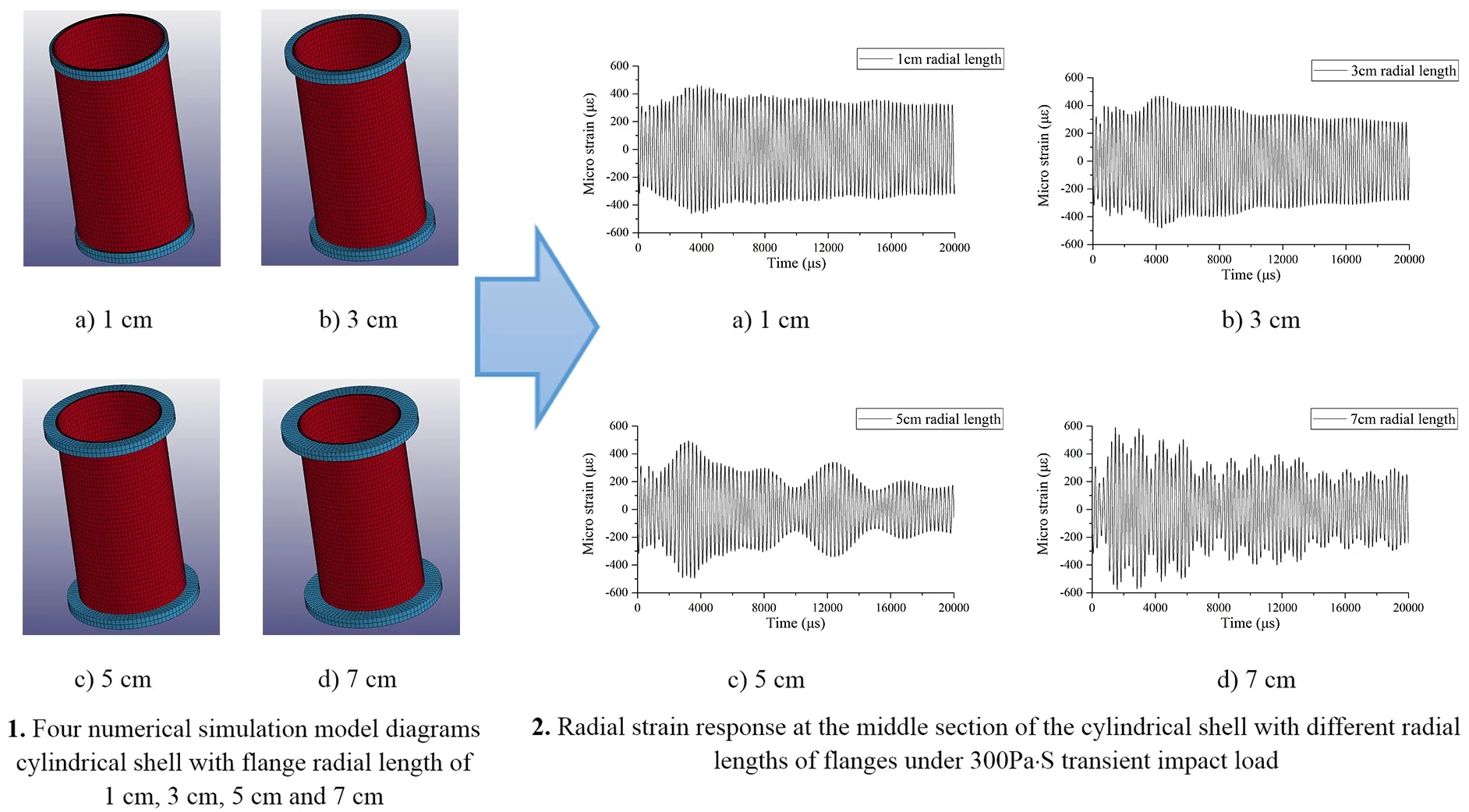
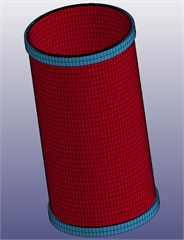
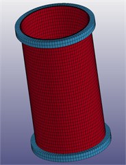
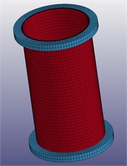
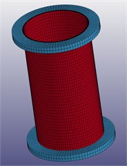
In order to explore the law of the effects of flange parameters on the strain growth of cylindrical shell, on the premise of unchanged boundary conditions, four numerical models of shell with different flanges of radial length are designed in this section, as shown in Fig. 1. The material model is also the same as that in the previous section. Compared with the model in the previous section, the models in this section are only added flanges with a uniform thickness of 4.26 cm at both ends. To eliminate the influence of quality on the results, all four flanges use the same quality. That is, the 3 cm flanges are set as the benchmark, whose material density is 7.83 g/cm3, and the density of the other three flanges is converted to 24.52 g/cm3, 4.51 g/cm3 and 3.10 g/cm3, respectively.
Without considering the effect of multiple convergence and reflection of shock wave, the impact load on the vessel wall is simplified as triangular wave pulse P(t) uniformly distributed on the inner wall of the vessel [14]. Where:
P0 is the peak pressure, t1 is the duration of the transient pressure. The pulse is applied to the inner wall using the keyword *LOAD_SEGMENT_SET. When the positive pressure action time of the impact load is very small, the response of the vessel mainly depends on the impulse of the load, and the waveform of the load has little effect on it [8]. Therefore, the impact load with positive pressure action time of 50 μs and impulse of 300 Pa·S is set in this paper.
Fig. 1Four numerical simulation model diagrams cylindrical shell with flange radial length of 1 cm, 3 cm, 5 cm and 7 cm
a) 1 cm
b) 3 cm
c) 5 cm
d) 7 cm
4. Results and discussion
As shown in Fig. 2, the radial length of the flange has an obvious influence on the maximum strain, strain growth factor and strain growth time, but it hardly changes the first peak strain. The features are summarized in Table 3.
It can be concluded from the figure that:
Firstly, the radial length of the flange has almost no effect on the value of the first peak strain, especially the first peak compressive strain, which is always about 318.3 με. This is because the flange is located at the end of the cylindrical shell, so the disturbance caused by it is not superimposed on the initial strain response of the middle section [15].
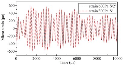
Secondly, the maximum strain and strain growth factor basically increase with the growth of the radial length of flange. When the radial length of flange is 1-5 cm, the increase of maximum strain and strain growth factor is relatively slow along with the radial length, while when the flange length increases to 7 cm, the growth of maximum strain and strain growth factor is more significant. The possible reason may be the fact that with the increase of flange length, the bending axisymmetric modal disturbance caused by flange becomes more severe, thus increasing the linear modal coupling response of cylindrical shell [7, 15]. As shown in Fig. 3, when the loading impulse of the cylindrical shell with flange length of 7 cm is set to 600 Pa·S, its strain response is extremely similar to that of the load of 300 Pa·S, indicating that the radial response of the middle section is indeed still a linear modal coupling response.
Fig. 2Radial strain response at the middle section of the cylindrical shell with different radial lengths of flanges under 300 Pa·S transient impact load

a)

b)

c)

d)
Finally, on the one hand, it can be found from the table that the strain growth time decreases with the increase of the radial length of the flange; On the other hand, it can be observed from the spectrum diagram that the increase of the radial length of the flange tends to stimulate the strain response at a higher frequency. Therefore, it can be concluded that when the high-frequency response is added with the strain response, it is easier to shorten the strain growth time.
In addition, it can be seen from the figure and table that when the flange length is 3 cm, the strain growth time of its tensile strain and compressive strain both bigger, which seems to deviate from the rule that the strain growth time decreases with the flange growth. However, in fact, when the flange length is short, the difference in the peak strain is not significant in the cycles around the maximum strain peak, so the difference in calculation and statistics does not affect the study of general rules. What’s more, when the flange length is 1 cm, the strain growth factor is slightly higher than that when the flange length is 3 cm, which is caused by the slightly lower value of its first peak strain.
In summary, in order to reduce the strain growth value, the flange with smaller radial length should be selected as far as possible when designing the explosion containment vessel.
Table 3Radial strain response characteristics at the middle section of the cylindrical shell with different radial lengths of flanges under 300 Pa·S transient impact load: a) compressive strain, b) tensile strain
Compressive strain | ||||
Radial lengths of flange | First peak compressive strain | Maximum compressive strain | Compressive strain growth factor | Compressive strain growth time |
1 cm | 318.3 με | 462.3 με | 1.452 | 4111.5 μs |
3 cm | 318.0 με | 481.5 με | 1.514 | 4346.4 μs |
5 cm | 318.3 με | 495.5 με | 1.557 | 3606.4 μs |
7 cm | 318.6 με | 577.9 με | 1.814 | 1587.9 μs |
Tensile strain | ||||
Radial lengths of flange | First peak tensile strain | Maximum tensile strain | Tensile strain growth factor | Tensile strain growth time |
1 cm | 310.8 με | 464.2 με | 1.494 | 3733.4 μs |
3 cm | 318.7 με | 469.1 με | 1.472 | 4470.4 μs |
5 cm | 314.2 με | 493.9 με | 1.572 | 3228.5 μs |
7 cm | 308.2 με | 593.2 με | 1.925 | 1472.0 μs |
Fig. 3Radial strain response at the middle section of the cylindrical shell with 7 cm radial lengths of flanges (under 600 Pa·S transient impact load) and one half of response (under 300 Pa·S transient impact load)
5. Conclusions
The radial length of the flange have significant effects on the strain growth of the explosion containment vessel. In this paper, numerical simulation is carried out for cylindrical shells with flanges at both ends under sliding-sliding boundary conditions, and the main conclusions are as follows:
1) The difference of flange radial length have little influence on the first peak strain. In particular, no matter how the flange length change, the first peak of compressive strain is almost the same for the same cylindrical shell subjected to the same impact load.
2) As the radial length of the flange increases, various frequency bending disturbances of the cylindrical shell are excited, which will enhance the linear modal coupling response of the cylindrical shell and increase the strain growth factor.
3) When more high-frequency parts are introduced into the strain response, the strain growth time will be correspondingly shortened.
4) It is recommended that the flanges should be as small as possible when designing vessels.
References
-
Karpp R. R., Duffey T. A., Neal T. R. Response of containment vessels to explosive blast loading. Journal of Pressure Vessel Technology, Vol. 105, Issue 1, 1983, p. 23-27.
-
Zhu W. H., Xue H. L., Zhou G. Q., et al. Dynamic response of cylindrical explosive chambers to internal blast loading produced by a concentrated charge. International Journal of Impact Engineering, Vol. 19, Issues 9-10, 1997, p. 831-845.
-
Duffey Thomas A., Christopher Romero Strain growth in spherical explosive chambers subjected to internal blast loading. International Journal of Impact Engineering, Vol. 28, Issue 9, 2003, p. 967-983.
-
Li Q. M., Dong Q., Zheng J. Y. Strain growth of the in-plane response in an elastic cylindrical shell. International Journal of Impact Engineering, Vol. 35, Issue 10, 2008, p. 1130-1153.
-
Dong Q., Li Q. M., Zheng J. Y., et al. Effects of structural perturbations on strain growth in containment vessels. Journal of Pressure Vessel Technology-Transactions, Vol. 132, Issue 1, 2010, p. 011203.
-
Liu Wenxiang, Zhang Qingming, Zhong Fangping, et al. Strain growth of spherical shell subjected to internal blast loading during plastic response. Explosion and Shock Waves, Vol. 37, Issue 5, 2017, p. 893-898, (in Chinese).
-
Dong Q., Li Q. M., Zheng J. Y. Strain growth in a finite-length cylindrical shell under internal pressure pulse. Journal of Pressure Vessel Technology-Transactions, Vol. 139, Issue 2, 2017, p. 021213.
-
Dong Q., Li Q. M., Zheng J. Y. Interactive mechanisms between the internal blast loading and the dynamic elastic response of spherical containment vessels. International Journal of Impact Engineering, Vol. 37, Issue 4, 2010, p. 349-358.
-
Dong Q., Li Q. M., Zheng J. Y. Further study on strain growth in spherical containment vessels subjected to internal blast loading. International Journal of Impact Engineering, Vol. 37, Issue 2, 2010, p. 196-206.
-
Dong Q., Li Q. M., Zheng J. Y. Guidelines for the design of multiple-use explosion containment vessels based on the understanding of the strain growth phenomenon. Journal of Performance of Constructed Facilities, Vol. 25, Issue 5, 2011, p. 394-399.
-
Dong Q., Gu Y., Hu B. Y., et al. Progress on mechanisms of the strain growth phenomenon in containment vessels. Proceedings of the ASME Pressure Vessels and Piping Conference, Vol. 5, 2012, p. 107-114.
-
Zhu W. H. Theoretical and Experimental Investigations on the Dynamic Response of Cylindrical Explosive Chamber. Ph.D. Thesis, National University of Defence Technology, 1994, (in Chinese).
-
Demchuk A. F. Method for designing explosion chambers. Journal of Applied Mechanics and Technical Physics, Vol. 9, Issue 5, 1968, p. 47-50.
-
Simoens B., Lefebvre M. H., Nickell R. E., et al. Analysis of the dynamic response of a controlled detonation chamber. Journal of Pressure Vessel Technology-Transactions, Vol. 133, Issue 5, 2011, p. 103-110.
-
Wenxiang Liu, Qingming Zhang, Fangping Zhong, et al. Further research on mechanism of strain growth caused by superposition of different vibration modes. International Journal of Impact Engineering, Vol. 104, 2017, p. 1-12.
