Abstract
In this research, the concept of elastic overpressure fluctuation is introduced on the basis of the overpressure theory in the arch action, the formation of overpressure in the arch action is investigated with the elastic fluctuation on the silo wall. The formation and elastic fluctuation of overpressure in arch action is analyzed systematically with the laboratory experiment and the PFC simulation which were established on the basic of a project example, the models achieve the arch action by changing factors such as the physical parameters of grain and cone half angle of the silo hopper. The results obtained indicate that the increment of pressure and the overpressure coefficient all decrease with height. And the overpressure started from the arch feet, propagated upward in the form of fluctuation on the silo wall. In addition, the overpressure fluctuations propagate uniformly which is illustrated by observing the time step of when the pressure fluctuations amplitude occur at each monitoring points. The results reveal the formation mechanism of the overpressure in arching, and the relevant research conclusions would be of great reference significance for the design of silo.
Highlights
- The formation mechanism of over pressure in the silo wall under arching conditions was revealed.
- The relationship between the intergranular force and displacement of the discrete element linear model was deduced.
- The propagation of over pressure fluctuations is relatively uniform.
1. Introduction
Silos are widely used in the industry with particulate engineering, the phenomenon of the material arch action occurs frequently, however, it would be difficult to reflect the overpressure formation mechanism in arching objectively by the existing laboratory experiment and theoretical calculation models. In order to adapt to the rapid development of the grain industry in recent years, in-depth research on the overpressure is imperative to conduct.
Theoretical calculation formulas to quantify the silo wall pressure have been proposed, such as the famous Jassen formula [1-3]. However, it only can be applied under the static conditions. The formation of overpressure also has been studied experimentally and theoretically [4-6]. There are many factors such as the moisture content of the material, the internal friction angle of grain, the geometry of the silo has great effects on the behavior of particles flow [7-9]. The arch action would lead to the emergence of overpressure on the wall [10], and most of the stress of granular materials in the silo is bore by the particles in the arch [11-13]. In practical engineering, the silo wall is not absolutely rigid, the formation of dynamic pressure during discharge was affected by the elastic deformation of the silo wall [14], however, the understanding of the mesoscopic overpressure formation mechanism not well established.
For the arch action, studying the formation of elastic fluctuation has important reference significance for revealing the overpressure formation mechanism. In view of this, a scale model was established with engineering examples, laboratory experiment and PFC discrete element simulation which established with this scale model were used to simulate the dynamical process of outflow, the formation and propagation mechanism of overpressure are analyzed by revealing the effect of elastic fluctuation on the arch overpressure.
2. The arch action and the overpressure fluctuation
2.1. Formation process of arch
Grain is a kind of granular materials. Granular materials have characteristics like both liquid and solid, but their physical properties are not the same as solid and liquid entirely. On a mesoscopic scale, the essence of granular materials is a collection of many discrete particles, showing a liquidity in some respects. On a macroscopic or bulk scale, the storage materials can still be considered isotropic granular aggregate.
The storage materials would not arch in the static condition. The “arch action” is a process of dynamic equilibrium. The particles in the silo fall under gravity during discharge. The particles show a complex flow behavior because of the friction and collision between the particles, and between the particles and their environment. The forces and moments in the system are renewed every moment. The particles could find the best place to transfer pressure through constant adjustment of position and stress. A complete force chain connecting the two walls of silo is formed gradually. No particle vacancy is allowed to exist in the force chain, which in order to achieve the transmission of force and the impediment to the flow of upper material. In addition, it is also required that the arch feet have enough strength to support the upper material. Since the formation of the force chain affects the outflow of the particles, the decrease of the particle’s velocity causes an inertial force in the same direction with the particles velocity.
2.2. Elastic overpressure fluctuation
In the process of the arch formation, the decrease of material velocity in the silo is not an integral, continuous process. In practical engineering, the silo wall is not absolutely rigid, the wall has elasticity. The overpressure on the wall at the arch feet causes a slight lateral expansion of the silo [15], more materials will inflow to the section because of the volume increase of the expansion section, and the density of the storage in the expansion section increase because of compaction. The inflow materials also have certain velocity, they flow in the expansion section, and their velocity would decrease to zero, then the inertial force would be produced.
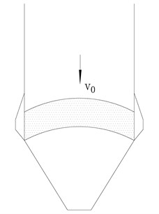
The wall expansion is illustrated in Fig. 1. Moreover, the velocity of particles in a micro region above the arch must be affected firstly and rapidly decreased to zero, then the inertial force appears, the silo wall pressure increases. The velocity of particles in the other micro region above the region aforementioned were further affected to decrease, the pressure on the wall section also be influenced.
The overpressure, caused by the materials continuously flowing into the expansion volume and the velocity of material decrease in order, propagates in the form of fluctuation from the arch feet.
Fig. 1Silo wall expansion
3. Similarity authentication
According to engineering examples, the main physical parameters involved in the unloading and arching process are: gravity acceleration (g), grain density (ρ), silo model geometry (L), wall elastic modulus (E), grain cohesion (C) the internal friction of food (φ1), the external friction of food (φ2), the stress of the silo wall (σ). Representation by the function:
The function can be obtained through the similarity criterion with the general function formula:
The simulation model was adopted with the scale model, and the geometric similarity coefficient is 1/20, because the density and the gravity acceleration were difficult to be changed in experiments, the density similarity coefficient Cρ= 1 and the similarity coefficient of gravity acceleration Cg= 1 were used. According to the Jassen formula, the stress similarity coefficient is estimated, it is used to certify the material similarity in the model test with the former similarity criterion [16], and the geometric similarity and stress similarity meet each other. Thus, it is proved that the model adopted can satisfy the similarity authentication. and the geometric similarity and stress similarity meet each other. Therefore, it is proved that the model could satisfy the similarity authentication.
4. Experimental method
4.1. Experimental model
The experimental model was established based on the engineering example of silo accident in Shandong, Xinliang [17]. In this project example, the geometrical scale was 20 m in height, 6 m in the inner diameter and 160 mm in wall thickness, and the diameter of the outlet is 1 m.
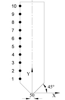
The scale model of 20:1 was studied in the experiment, the geometrical symbols of the silo are illustrated in Table 1 and Fig. 2.
Fig. 2The geometrical symbols of the silo for experiment
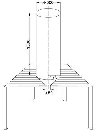
Table 1The geometrical symbols of the silo for experiment
Internal diameter (mm) | Wall thickness (mm) | Wall height (mm) | Outlet diameter (mm) | Cone half angle (°) |
300 | 8 | 1000 | 50 | 45 |
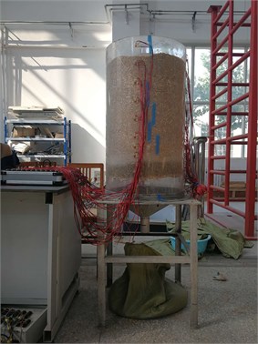
The silo is made of plexiglass with a thickness of 8 mm for convenient viewing. The experimental model silo is filled with wheat with the diameter of 5 mm to 6 mm. The plate of the outlet is removed to perform the discharging experiment after charging is completed. Repeat experiments to achieve the “arch action” by adding dust, changing the moisture content, placing sandpaper on the wall, and changing the properties of the wheat. The grain arch is shown in Fig. 3.
Fig. 3Experimental model
4.2. Monitoring points
10 monitoring points are arranged along the left side silo wall, strain gauges are placed on each monitoring point to monitor the pressure. The pressure for the arch action could be obtained. The distribution of the monitoring points is shown in Fig. 4.
Fig. 4The distribution of the monitoring points on silo wall
4.3. Experimental results
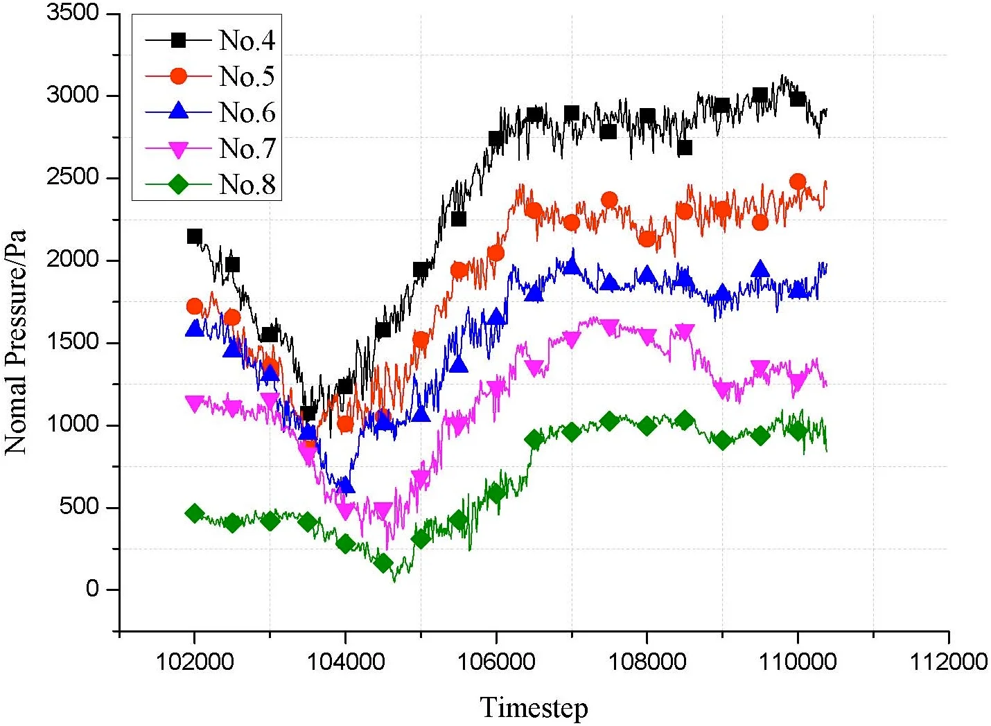
The pressure at the monitoring points numbered 4, 5, 6, 7, and 8 were selected to monitor. The pressure at each monitoring points is shown in Fig. 5.
Fig. 5The pressure at the monitoring points
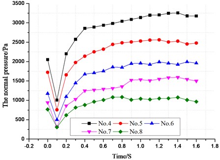
In the experimental results, after the unloading of the silo, there is a momentary drop in the pressure inside the 0.1 seconds, and the side pressure fluctuation reaches the maximum with the formation of the arched force chain. The formation of the “arch action” pressure could be clearly seen through the chart of the dynamic silo wall pressure, the pressure fluctuated during discharge, and the overpressure for arch action occurrences in the fluctuation peak. But limited by objective experimental conditions, it is difficult to reflect the formation of overpressure at mesoscopic scale accurately. Therefore, there would be further research by PFC simulation in the later part of the paper, and the results of experimental method would be compared with simulation to prove the accuracy of PFC simulation.
5. Discrete element simulation
5.1. Contact model and constitutive model
5.1.1. Linear contact model
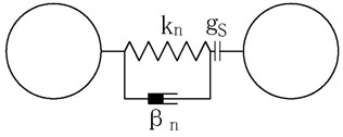
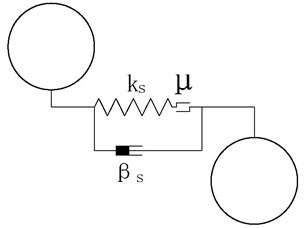
The linear contact model is used to simulate the interaction contact force between the particles themselves and between the particles and the walls. The conventional linear contact model is one of the PFC mechanical models, it stipulates the infinitesimal interface between two elements, and it has no additional limits on the rolling of particles. The contact force is provided by the linear components and the dashpot components. The linear components provide the tension-free linear elastic force and friction (kn, ks and μ), while the dashpots provide the cohesion between the two particles (βn, βs). The linear element is equivalent to a spring or a sliding plate, the dashpot is equivalent to a damper. A surface gap, gs is defined as the difference between the contact gap and the reference gap so that when the reference gap is zero. The contact model as shown in Fig. 6.
5.1.2. constitutive model
1) Between particles.
The unit vector model and the contact deformation of two particles are obtained by Newton’s Second Law of motion. Two particles i and j are in contact with each other, as shown in the Fig. 7. The central coordinates of two particles are (xi,yi), (xj,yj) respectively. There is little difference in the particle diameter distribution of wheat, therefore, it can be considered that the radius of both particles is rc normal vector at the point of contact is →n=(nx,ny) the tangential vector is →t=(tx,ty).
Which can be obtained:
where →vi, →vj are used to represent the velocity at the center point of particles called i, j the relative velocity of the two particles at the contact point can be expressed as:
Fig. 6Linear contact model: a) tangential contact model, b) normal contact model
a)
b)
Fig. 7Contact between two particles
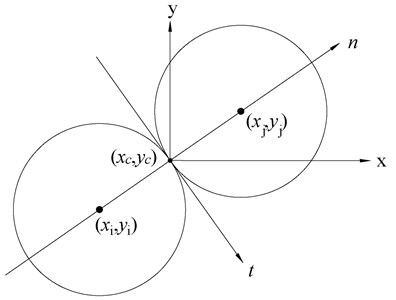
The velocity of particles I and j contact points can be expressed by Eq. (6), (7):
which can be obtained:
The normal and tangential components of the relative velocity is:
For the particles i, j the normal and tangential velocity components of velocity at the contact point both cause displacements in the corresponding directions. According to the velocity component calculated in the above manner, the variation of displacement component within a moment could be obtained as:
According to the law of force displacement:
Could be obtained, the motion equation of the particle i could be obtained by Newton’s Second Law of motion:
where I is the particles’ moment of inertia. In the linear contact model, it is generally considered that the moment at particle contact point is always zero).
Mesoscopic parameters are changing at every moment in the operation. Taking particle i as an example, the force is updated in a time stepping like:
The velocity is updated in a time stepping like:
The position of particle is updated in a time stepping like:
2) Particles and walls.
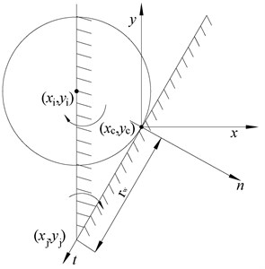
The wall j revolve around (xj,yj), and the central coordinates of the particle i is (xi,yi). The coordinates of the contact point between the wall and the particle is (xc,yc). The normal vector at the point of contact is →n=(nx,ny), while the tangential vector is →t(tx,ty)→vi, →vj is used to express the velocity at the center point of particle i and the rotation center of wall j, respectively the relative velocity at the contact point could be expressed by:
where wj is the angular velocity of the wall rotation. The wall would not translate, so vj= 0:
The component of relative velocity in the normal and tangential direction is:
The updating methods of contact force normal and tangential increment, position and velocity are all mentioned above.
Fig. 8Contact between particle and wall
5.2. Simulation model and parameter
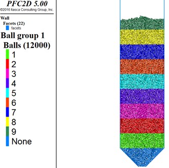
According to the existing experimental model size [11], the simulation model uses the same scale model to study the dynamic simulation. A silo model with an internal diameter of 300 mm, a height of 1000 mm, a outlet diameter of 50 mm, and the cone half angle of 45° is built to simulate particle flow with PFC2D.The particles gradually settle on to the silo, the physical parameters of the wheat and walls, as shown in Table 2, were selected on the basis of the grain properties provided in document. The charged particles are shown in Fig. 9. Then delete the wall of the outlet, the materials will discharge, there are arched stress chains in the vicinity of the outlet under the “arch action”.
Table 2The parameters of particles and walls in simulation
Density / kg·m-3 | Internal friction coefficient | External friction coefficient | Water content / % |
1000 | 0.43 | 0.62 | 17.9 |
Table 3The parameters of the walls and particles
Wall-kn/N·m-1 | Wall-ks/N·m-1 | Ball-kn/N·m-1 | Ball-ks/N·m-1 |
3e7 | 2e6 | 3e7 | 2e6 |
In addition, the simulation parameters about the walls and particles are listed in Table 3. the wall and particles in the simulation are represented as ‘Wall’ and ‘Ball’ respectively, where the kn and the ks are their normal and tangential stiffness.
20 virtual monitoring points are arranged along the wall to monitor the silo wall pressure. The monitoring results would be compared with the experimental method result, it is found that the fluctuation tendency of pressure in the experiment is consistent with the simulation result, which can prove the accuracy of the PFC simulation.
Fig. 9The charged particles
5.3. Monitoring points
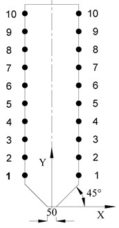
The particles present a complex, asymmetrical, non-uniform flow structure. Therefore, according to the above experimental model, 20 monitoring points are uniformly distributed on the wall at intervals of 100 mm, to monitor the pressure at each points. The distribution of monitoring points is shown in Fig. 10.
Fig. 10The distribution of monitoring points in simulation
6. Results and analysis
Arch is the key of the research, dynamic simulation analysis is performed for discharge and grain arch. Firstly, the PFC discrete element simulation is adopted to achieve arch by changing the parameters of materials. The particles of “arch action” is shown in Fig. 11.
6.1. Stress chains
The velocity, position and stress of particles change constantly and a irregular force chain in arch on both wall sides is gradually formed during discharge. If the particles can transfer stresses well and the arch feet have enough strength, the arch, which hinders the outflow of the granular materials, would form. The formation of force chain in arch is shown in Fig. 12.
Fig. 11The model of the arch in silo
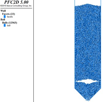
Fig. 12Force chain formation process
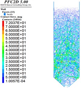
a) 105000 timestep
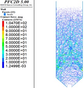
b) 106000 timestep
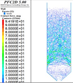
c) 107000 timestep
6.2. Simulation results
In this simulation, the arch feet form in the lower 1/3 part of the silo wall. Therefore, the pressure at monitoring points in the upper 2/3 part in silo is affected by the arch action, while the pressure of the monitoring points 1, 2, 3 was not affected. And when the arch forms, a part of particles in silo have been discharged, a zero pressure area on the wall have appeared in the upper 1/5 part of the wall. In summary, monitoring points numbered 4, 5, 6, 7, 8 were selected for observation and analysis.
The pfc software could directly demonstrate the dynamic pressure, but it was difficult to observe the pressure at each time step accurately. Therefore, in this article, pfc was used to output the Excel, which illustrates the pressure at each step, form a linear graph of dynamic pressure on silo wall. The dynamic pressure of the five points on the left wall is shown in Fig. 13. For the arch action, the pressure distribution and overpressure coefficient are shown in Fig. 14 and Table 4.
Table 4Overpressure coefficient on the left wall
No. 4 | No. 5 | No. 6 | No. 7 | No. 8 | |
Pressure / Pa | 3033.9 | 2264.1 | 1955.3 | 1614.9 | 1044.4 |
Jassen value / Pa | 1039.5 | 984.0 | 912.0 | 815.0 | 680.0 |
Overpressure coefficient | 2.92 | 2.30 | 2.14 | 1.98 | 1.54 |
The dynamic pressure of the five points on the right wall is shown in Fig. 15. For the arch action, the pressure distribution and overpressure coefficient are shown in Fig. 16 and Table 5.
Fig. 13The dynamic pressure on the left wall
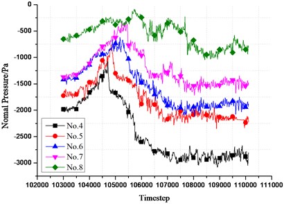
Fig. 14Pressure for each on the left wall
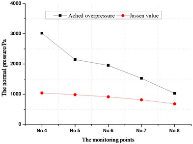
Fig. 15The dynamic pressure at each monitoring point on the right wall
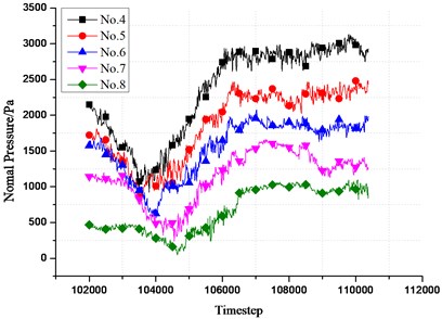
Fig. 16Pressure at each monitoring point on the right wall
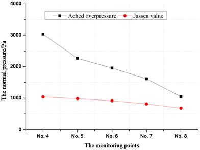
It could be clearly seen that the pressure of silo wall and the overpressure coefficient for the arch action increase with depth, in addition, the overpressure of different monitoring points for the arch action would not occur at the same time. It perhaps related to the particle velocity decrease in order and related to the elastic deformation of wall propagating from the arch feet to the upper part.
Table 5Overpressure coefficient on the right wall
No. 4 | No. 5 | No. 6 | No. 7 | No. 8 | |
Pressure / Pa | 3019.60 | 2147.70 | 1952.10 | 1525.20 | 1028.50 |
Jassen value / Pa | 1039.50 | 984.00 | 912.00 | 815.00 | 680.00 |
Overpressure coefficient | 2.90 | 2.18 | 2.14 | 1.87 | 1.51 |
6.3. Analysis about elastic fluctuation
The simulation results demonstrated the order of different points overpressure occurrence for the arch action on the left wall, as shown in Fig. 17.
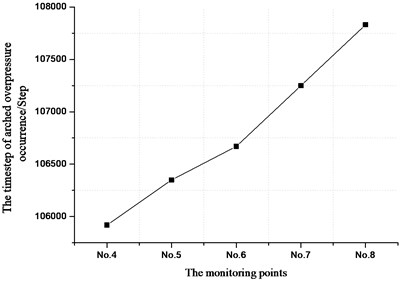
The simulation results demonstrated the order of different points overpressure occurrence for the arch action on the right wall, as shown in Fig. 18.
In view of the symmetry of the silo structure, most scholars deem that the distribution of mesoscopic parameters in silos should also be symmetrical. However, in the actual project, the flow of the particulates in the silo is complex, showing non-uniformity and asymmetry, the time step of different points overpressure occurrence for the arch action and propagation of elastic overpressure fluctuations on different wall sides are all slightly different. In case of the left wall, as could be demonstrated from Fig. 17, overpressure for arch action at the No. 4 monitoring point occurs earliest, the overpressure for arch occurs when 105850 steps are simulated. As the simulation continues to calculate, the pressure for the arch action at 4, 5, 6, 7, 8 monitoring points produced in order. The overpressure for the arch action at the No. 8 monitoring point occurs when 105920 steps are simulated. Although the elastic fluctuation on the right wall is slightly different from the result on the left wall, it could be demonstrated from Fig. 18. Fig. 9 that the propagation of overpressure fluctuation is still almost uniform.
Fig. 17The time step of overpressure occurrence for the arch action on the left wall
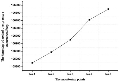
Fig. 18The time step of overpressure occurrence for the arch action on the right wall
7. Conclusions
The mesoscopic mechanism and dynamic law of elastic overpressure fluctuation on the silo wall are further studied by laboratory experiments and dynamic simulation in this research. The following conclusions are obtained:
1) The overpressure occurs on the wall when the grain arch, the main reason for overpressure is the inertia force caused by the decrease of particles velocity.
2) Observing the fluctuation of the pressure on the silo wall, it could be demonstrated that the arched overpressure of fluctuation occurs in order with height, indicating that the overpressure fluctuation starts from the arch feet and propagates upward. The decrease in particle velocity is also propagate upward, gradually.
3) During discharge and arch, the pressure, the increment of overpressure and the overpressure coefficient at each monitoring points all decrease with height.
4) The time interval of the stable arched overpressure occurrence between any two adjacent monitoring points is relatively uniform, and it can be concluded that the propagation velocity of overpressure fluctuations is also stable.
The research results reveal in depth the formation mechanism of the overpressure on the silo wall in arching. The relevant research conclusions can be used as a reference for the design of silo.
References
-
Su Le Xiao Stress analysis of grain static pressure in silo. Journal of Zhengzhou Grain College, Vol. 3, 1990, p. 72-76.
-
Ding Sheng Wei Discrete Element Analysis of Silo Lateral Pressure Based on Pfc3D. Ph.D. Thesis, Wuhan University of Technology, 2014.
-
Lu Sai Experimental Study on Lateral Pressure of Eccentric Unloading Side Wall of Large Diameter Concrete Shallow Silos. Ph.D. Thesis, Nanjing University of Science and Technology, 2016.
-
Du Mingfang, Zhang Zhao, Zhou Jian Numerical simulation of silo pressure and flow pattern in granular flow. Special Structure, Vol. 4, 2004, p. 39-41.
-
Wieckowski Z. Numerical modeling of silo discharge. Computing in Civil and Building Engineering, Vol. 2, 2000, p. 764-771.
-
Su Le Xiao Mechanical analysis of over pressure of silo wall during discharging of silo. Journal of Zhengzhou Grain College, Vol. 4, 1998, p. 17-21.
-
Zhang Zhirong Experimental Study on Dynamic Lateral Pressure of Cylinder Wall Unloading. Ph.D. Thesis, Henan University of Technology, 2017.
-
Pang Kun Experimental Study on Unloading Pressure of Silos. Ph.D. Thesis, Henan University of Technology, 2016.
-
Zhang Man Numerical Simulation of Lateral Pressure in Unloading Silos. Ph.D. Thesis, Henan University of Technology, 2014.
-
Chen Changbing, Liang Xingpei Discrete element simulation analysis of unloading process of silos. Grain and Oil Technology, Vol. 1, 2008, p. 11-13.
-
Matchett A. J. The Shape of the cohesive arch in hoppers and silos – some theoretical considerations. Powder Technology, Vol. 17, 2007, p. 133-145.
-
Hidalgo R. C., Lozano C., Zuriguel I., et al. Force analysis of clogging arches in a silo. Granular Matter, Vol. 15, 2013, p. 841-848.
-
Carlevaro C. M., Pugnaloni L. A. Arches and contact forces in a granular pile. The European Physical Journal E, Vol. 35, 2012, p. 44.
-
Su Le Xiao Elastic deformation of silo unloading and arching and its effect on silo wall pressure. Journal of Zhengzhou Grain College, Vol. 4, 1997, p. 59-63.
-
Cai Tongxiang, Wang Xuewen, Wang Shuping, et al. Analysis of excess pressure and deformation during unloading of silos. China Powder Technology, Vol. 4, 2014, p. 15-19.
-
Lu Linlin Study on the Friction and Compression Properties of Grain in Large Storehouses. Ph.D. Thesis, Nanjing University of Finances and Economics, 2012.
-
Ren Jie, Han Yang Research status of grain arching mechanism and prevention technology. Henan Science and Technology, Vol. 13, 2015, p. 102-104.
About this article
The financial support for this research came from The National Natural Science Fund Project (51708182), the Basic Research Project of Henan Education Department (Grant No. 16B560002).

