Abstract
This paper presents a study on the ultimate bearing capacity of circular shallow foundation in frozen clay. The bearing capacity were determined by model test, numerical simulation and analytical solution. In numerical simulation, the temperature field considering the phase transition was transformed into a temperature load and applied to a three-dimensional solid model. The generalized Kelvin model was used to describe the creep of frozen clay, and step loading was used. Based on the tests results that frozen soil fails because of local shear, we proposed an analytical model to estimate the ultimate bearing capacity of circular shallow foundation with local shear failure mechanisms. Based on the limit equilibrium theory, it was assumed that the fracture plane of the model only develops to the boundary between the transition zone and the passive zone. The results from present study and some other method are presented and compared, which has shown and verified the feasibility of our method. And the analytical solution is in good consistent with the results of the model test and numerical simulation.
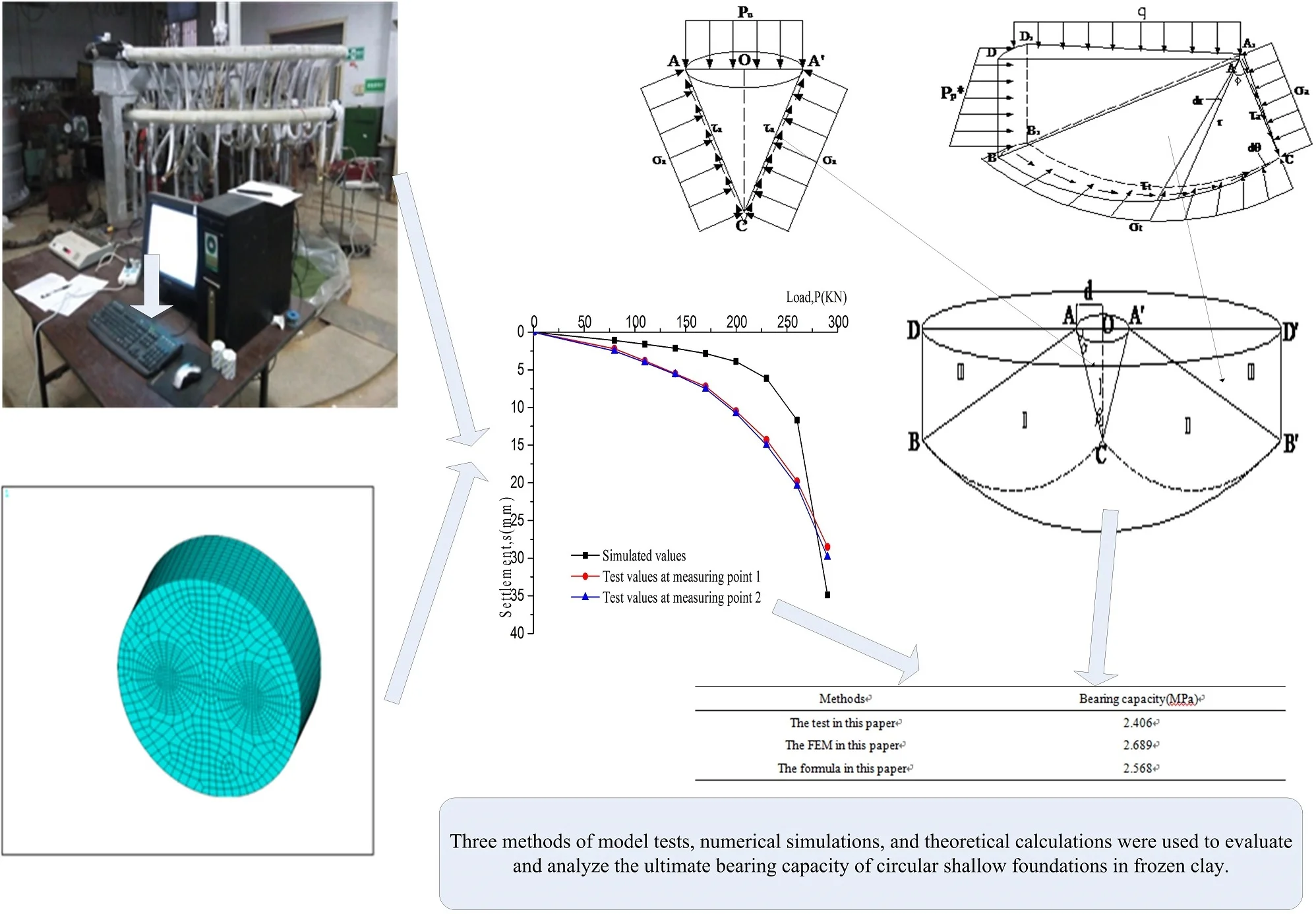
Highlights
- Model test on bearing capacity of artificially frozen clay foundation.
- Frozen clay fails by local shear mechanisms.
- Three-dimensional numerical simulation of frozen clay by ANSYS software.
- The calculation model of circular foundation under local shear failure mode is given.
1. Introduction
Frozen soil refers to rocks or soils with temperatures below 0 °C and contains ice. It can be divided into permafrost, seasonal frozen soil and short-term frozen soil. The permafrost area account for 23 % of the dry land surface of the world, mainly distributed in Russia, Canada, China and the Alaska of United States and some others [1].
As one of the classical stability problems in soils mechanical, the foundation bearing capacity has always been the focus of scholars and engineers. In recent years, many scholars have devoted themselves to the ultimate bearing capacity and deformation of pile foundations [2-4]. In permafrost regions, shallow and deep foundation are the two commonly used types. Shallow foundation should be preferred over other types because of its advantages of saving materials, easy construction, simple technology and low price. The pioneer work can be traced to Ladanyi [5], and he proposed a method for predicting the long-term settlement of shallow foundations on relatively warm frozen soils. Later, many scholars had turned their attention to the bearing capacity of the pile foundation in frozen soil. Over the course of the past 40 years, a number of plate load tests were carried out to analyze the bearing capacity of pile foundations and the influence of various factors in frozen soil [6-9]. Some scholars conducted a series of model tests on piles of different shapes and have found that different piles have different forms of damage in frozen soil, for example, the load-settlement curve of square pile has a steep drop, while the damage of conical pile is relatively slow [10-12]. The bearing capacity of the pile foundation is closely related to the interaction between pile and soil. For frozen sand, the bearing capacity of the pile foundation is mainly provided by the cohesion of frozen soil layer on the pile side [13, 14]. However, due to the influence of frost heave and thaw settlement of frozen soil, the damage of pile foundations is often occurred [15]. Therefore, it is of great significance to study shallow foundation in frozen soil. Considering circular footing is one typical shallow foundations, the aim of this paper is to study the ultimate bearing capacity of circular shallow foundation in frozen clay through model test, numerical simulation and analytical solution.
In frozen soil, foundations often subject to local shear failures, which is observed by experimental and numerical studies. In consequence, there are lots of scholars have studied the ultimate bearing capacity of foundation with local shear failure mode [16-18]. There are lot of studies about the ultimate bearing capacity of circular footing in recent years [19-23], but only a few empirical formulas can reflect the impact of circular shallow foundation subject to local shear failures [24, 25], and their details will be discussed later. In present study, the analytical solution of ultimate bearing capacity suitable for circular shallow foundation under local shear failure mode is proposed. The results can provide theoretical references for engineering in permafrost areas.
2. Existing solutions
The ultimate bearing capacity of shallow foundations in weightless soil can be determined by the following equation [26]:
where pu is ultimate bearing capacity; c is cohesion of soil; Nc and Nq are bearing capacity factors for strip foundations; sc and sq are shape factors of the foundation; γ is unit weight of soil; and D and B are depth and width of the foundation, respectively.
Some analytical solutions could estimate the ultimate bearing capacity of circular shallow foundation under local shear failure mode, mainly including the Terzaghi empirical formula and the Vesic correction method.
(1) Terzaghi [24] recommended that when local shear failure was expected, the shear strength should reduce by 2/3, that is, c*=23c and φ*=arctan(2tanφ3) ,and the ultimate bearing capacity can be estimated using the following expression:
where:
For the circular footing subjected to local shear failure mechanisms, it can be estimated as follows:
(2) Vesic [25] proposed that when the stiffness index of foundation Ir<Ir(cr), the foundation would fail by local or punching shear mechanisms, which can be estimated as follows:
where:
However, due to the strong nonlinearity of frozen soil, there are some limitations in applying these theories to the design of shallow foundations in frozen soil, and the expanding cavity model can be used [27, 28]. It is based on the nonlinear isochronous stress-strain and strength curves of frozen soil, and thought that frozen soil will reach the ultimate state when it enters the third creep stage, which can be estimated as follows:
where p0 is the ambient pressure, and it is equal to the average original normal pressure at the level of the punch. For circular footing, Nq and Nc can be described by:
where φ is the internal friction angle, n is the creep exponent, Ir is rigidity index, εf is the failure strain, k and Ir are defined by:
where f is the flow value given by:
However, the model is mainly used for the design of deep foundations, and for shallow foundations the ultimate bearing capacity is low.
3. Experimental study
3.1. Test device and procedure [29]
The model test system mainly includes refrigeration system, circulation system, data acquisition system, control system and test platform etc. (as shown in Fig. 1). The experimental platform is a circular pit in the Institute of Frozen Soils of Anhui University of Science and Technology. Its radius and depth are 1.5 m and 0.9 m, respectively. The soil samples are Huainan clay, and its basic physical parameters are listed in Table 1. A high-precision refrigeration system using alcohol was used in the experiment, and the soil was reduced to the specified temperature by artificial freezing tubes. The temperature of the freezing tubes was –15 °C, and the layout of the freezing tubes are shown in Fig. 2. The circular rigid plate whose load was directly applied to the frozen soil by the hydraulic jack, and the fast load-keeping method was adopted, which was divided into 8 steps with an interval of 1 h. The data acquisition used a high-precision YE2532 static strain gauge, and the whole process of the test was controlled by computer. For comparison, we also carried out a model test of the foundation bearing capacity of clay, and the specific arrangement is consistent with the frozen soil.
Fig. 1Model test system
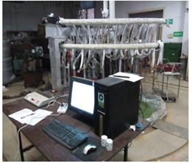
Fig. 2Layout of freezing tubes
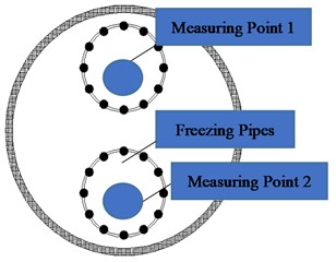
Table 1Basic physical indicators of soil samples
Soil | Water content (%) | Density (g/cm3) | Porosity (%) | Liquid limit (%) | Shrinkage limit (%) | Saturation (%) |
Clay | 23.2 | 1.788 | 0.708 | 35.6 | 19.3 | 1.0 |
3.2. Test results
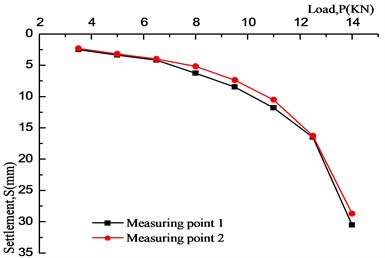
The load-settlement (P-S) curve of frozen clay at –15°C and conventional clay are shown in Fig. 3 and 4. As we can see:
(1) The strength of the frozen clay is larger and the ultimate bearing capacity is stronger than unfrozen soil, which is due to the water in the soil are converted into ice at low temperature. At this time, the strength is mainly affected by the cementation of the ice, which is also the main influence of temperature on the strength of frozen soil.
(2) Those load-settlement curves of frozen clay all have proportional limitation of 170 kN and are equal in size, this shows that the ultimate bearing capacity of frozen clay is about 2.41 MPa.
(3) Conventional clay fails by general shear mechanisms, and frozen clay fails by local shear mechanisms. This could be determined by the P-S curves, which the P-S curve of local shear mechanisms often haven’t obvious turning point, and it’s mainly characterized by deformation, the sliding surface did not develop to the ground.
Fig. 3P-S curve of frozen clay at –15°C
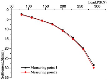
Fig. 4P-S curve of conventional clay
4. Constitutive equation of frozen clay
4.1. The generalized Kelvin model
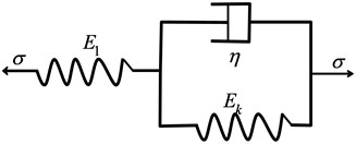
The creep characteristic of frozen soil is complex. Many scholars have studied it, and several frozen soil creep models have been established [30-34]. The creep curves for frozen clay can be described by the generalized Kelvin model consisting of a Hooke element and a Kelvin elements (Fig. 5).
Fig. 5The generalized Kelvin model
The constitutive equation is:
The creep equation is:
where εe and εve represent the elastic strain and the viscoelastic strain, respectively; E1 is the elasticity parameter of spring in the generalized Kelvin body; Ek is the elasticity parameter of spring in Kelvin body; η is the viscosity coefficient of a dashpot in the generalized Kelvin body; t is time.
4.2. Model flexibility matrix [35]
It can be seen from Fig. 5 that strain of the generalized Kelvin model can be decomposed into elastic strain and viscoelastic strain. Elastic strain can be determined by the generalized Hooke’s law. For three-dimensional axisymmetric problems, assuming the stress boundary conditions remain unchanging, and the Poisson’s ratio does not change with time [36], the elastic strain can be expressed as:
Assuming that the soil is isotropic, the three-dimensional the matrix [C] can be express:
Considering the rheological properties of the generalized Kelvin model, the basic form of the creep equation is obtained from the rheological constitutive equation by substituting the differential operator and solving the differential equation:
Rewrite the Eq. (17) and (19) into tensor form:
Thus, the three-dimensional differential constitutive relationship of the generalized Kelvin model under the constant Poisson's ratio can be expressed as:
4.3. Creep test of frozen clay
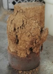
The uniaxial creep tests of frozen clay were graded loading, and the loading coefficients were 0.3, 0.5, and 0.7, respectively. The specimen was a cylinder with a diameter of 50 mm and a height of 100 mm. It was prepared by multi-layer wet tamping method (as shown in Fig. 6). After demoulded, it was placed in a low temperature box at –15°C for 48 hours and taken out for testing. Fig. 7 shows a damage specimen after the test. The test results are shown in Fig. 8.
Fig. 6Specimen in creep test
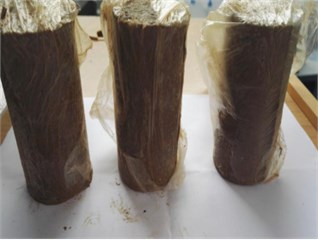
Fig. 7Specimen after test
Simulated annealing algorithm was used to optimize the parameters of the general Kelvin model [37]. The specific parameters are shown in Table 2. The uniaxial creep test results and calculated results of the generalized Kelvin model of artificially frozen clay at –15 °C are shown in Fig. 8. It can be seen that the generalized Kelvin model could well describe the creep of frozen clay.
Fig. 8Experimental and calculated results of uniaxial creep tests of artificially frozen clay at –15 °C
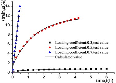
Table 2Parameters of the generalized Kelvin model
Loading coefficients | E1 (MPa) | Ek (MPa) | η (noise) |
0.3 | 4.0279 | 1.9239 | 2.8783 |
0.5 | 1.1671 | 0.1614 | 0.2340 |
0.7 | 2.7073 | 0.1208 | 0.1535 |
5. Numerical simulation
Similar to the conditions of the model test, numerical models were constructed using ANSYS software. In simulating, the same condition of soil and dimensions with model test was modeled in the numerical models. The generalized Kelvin model was used to simulate creep characteristic of frozen clay. The standard boundary conditions (i.e. total fixity at the bottom and horizontal fixities at the sides of the model) were defined.
5.1. Numerical model
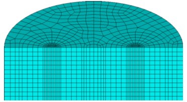
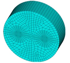
The finite element program ANASY is applied for the numerical simulation. The finite element model is consistent with the model test, that are its radius and depth are 1.5 m and 0.9 m, respectively. The eight-nodes hexahedral element type with independent temperature degrees of freedom are adopted and it has plasticity, creep, swelling, stress stiffening, large deflection and large strain capabilities. The mesh size is between 140 mm×70 mm and 20 mm×20 mm. After meshing, there are 10669 elements generated. The FEM model and mesh division are shown in Fig. 9.
Fig. 9Finite element meshes
a)
b)
5.2. Parameters
The parameters of the soil, such as thermal conductivity and specific heat, are changing with the state of the soil. Consequently, the influence of the phase transformation on the soil parameters should be taken into considered. The parameters are shown in Table 3.
Table 3Thermo-physical properties of soil
Soil state | Thermal conductivity (m2·s-1) | Specific heat capacity (J·(Kg·m3)-1) | Gravity density (KN·m-3) |
Frozen soil | 6.121 | 0.767 | 17.88 |
Unfrozen soil | 4.725 | 0.824 | 17.88 |
5.3. Numerical test results
Firstly, a three-dimensional solid model was established, and the temperature load was applied to the model. Then the step loading method was applied to simulate the multi-stage loading, and loading mode was consistent with the model test loading.
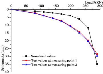
The comparison between simulation results and model test results are shown in Fig. 10. As can be seen that the simulation results are consistent with model test results. Those curves are composed of three stages, but the settlement values have a certain gap. When the load is small, numerical results are smaller than experimental results, this is mainly due to the foundation soil produces initial settlement under the action of its own weight, but the numerical model don’t take initial settlement into account; as load increases, numerical results gradually greater than experimental results, the frozen soil is regarded as ideal elastoplastic body when simulates. But in fact, the properties of the frozen soil are very complicated, which is closer to viscoelastic material and difficult to fully describe its properties with a simple component model.
Meanwhile, the generalized Kelvin model often overestimates the third-stage creep of the soil. In this paper, we pay more attention to the failure mechanism and ultimate bearing capacity of frozen soil foundation, the creep properties of the frozen soil can be approximated describe by the generalized Kelvin model. And the room temperature is higher than the freezing temperature during testing. Although we had taken some measures to maintain the heat, there is inevitably heat transfer between the soil and air, which brings difficulties to our numerical simulation, so it is simplified, this also leads to some differences in the results of the simulation. Compared with the P-S curves, there are obvious proportional boundary points. The boundary is bounded by the point, and both segments are close to linear, which is consistent with the P-S curve law of local shear failure, this is consistent with the observation from model test. In addition, the compaction and freezing degree of the soil in model test can also affect the result. The bearing capacity can be determined by the proportional limit of the P-S curves, the numerical result is about 190 KN, which is larger than experimental result of 170 KN. The error determined by the two methods is within 15 %, therefore, it could be considered that the simulation results are in agreement with the actual.
Fig. 10Comparison between simulation values and model test values
6. Formula derivations
A brief summary of some of the relevant methods in ultimate bearing capacity are presented in Sec.1. Due to local shear mechanisms of foundations in frozen soil, the general shear failure rarely finds. Moreover, in the study, the circular shallow foundation is adopted, which has been widely used in permafrost regions. However, the existing analytical solutions are all empirical formulas, and they are based on basis theory. Therefore, the analytical solution for the estimation of the ultimate bearing capacity of the circular shallow foundation in frozen soil is proposed in this section.
6.1. Basic assumptions [17, 21, 24, 38]
(1) The soil is weightless media.
(2) The base in foundations is completely smooth.
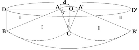
(3) The failure plane of local shear failure conforms to the Prandtl sliding failure surface, and the sliding zone consists of the active zone I, the transition zone II and the passive zone III. It is shown in Fig. 11, and d is the radius of circular foundation:
where φ is the internal friction angle in soil.
(4) In the range of embedding depth of foundation, the friction between the foundation and soil and the shear strength of the soil on both sides of the foundation are not taken into account, and the weight of the buried soil on both sides is simplified as overloading.
Fig. 11Idealized failure mechanism.
6.2. Analytical solution
6.2.1. Analysis of active zone
For the circular foundation, under the assumption of the local shear failure mode, the force of the active zone is shown in Fig. 12. The positive stress on the active failure surface is σa, the shear stress is τa, and it is equal to the cohesion.
Fig. 12External forces acting on the active area
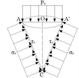
As shown in the Fig. 12, the surface area of the cone (except the area of the top) is:
From the vertical force balance condition of the active zone, it is obtained:
that is:
6.2.2. Analysis of transition zone and passive zone
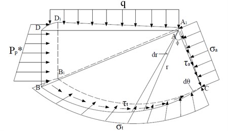
Since the local shear failure fracture surface extends into the passive zone, it can be considered conservatively that the fracture plane only develops to the boundary between the transition zone and the passive zone, that is, point B in Fig. 11. Compared with the general shear failure mode, the main difference between the two modes is that the pressure in the BDD1B1 plane changes from passive earth pressure Pp to non-limiting Rankine passive earth pressure P*p [39]. A micro-body of the transition zone and the passive zone is subjected to force analysis (Fig. 13). In the figure, BC is a log spirals, where r is the radius of the spiral, r=ACexp(ϕtanφ). The moment balance conditions of the micro-body to point A are:
(1) The area of plain ADD1A1 is:
The force on plain ADD1A1 is the ground overload q, and the moment on point A is:
(2) For the area of plain BD1DB1, the length of BB1 can be approximated to be equal to the length of DD1:
The force on the plain BD1DB1 is the non-limiting Rankine passive earth pressure, and its specific expression is:
The moment of force on A is:
(3) The force on the surface CBB1 is normal stress σt, the direction of action points to the pole A of the helix, and the shear stress τt, the magnitude is equal to the cohesion, and is evenly distributed along the boundary. The moment of the surface force on the point A is:
(4) The area of plain CAA1 is:
The moment of force on A is:
Due to static equilibrium conditions ∑MA=0, there are:
Substituting Eqs. (27), (30), (31) and (33) into Eq. (34), as follows:
Substituting Eq. (35) into Eq. (25), for brevity, it can be written as:
In which:
⋅[1+tan(π4+φ2)eπ2tanφ][2tan2(π4+φ2)+1-sinφ],
·[1+tan(π4+φ2)eπ2tanφ]+tan(π4+φ2).
Fig. 13External forces acting on the transition zone and passive zone
6.2.3. Comparison with empirical formulas
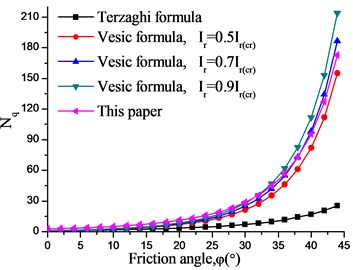
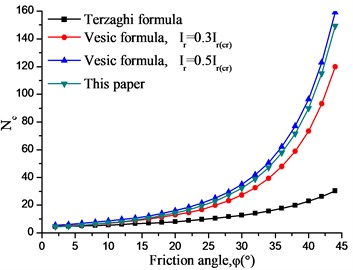
Fig. 14 compares the results of Nc and Nq from Terzaghi empirical formula, Vesic empirical formula, and our method in this paper. As can be seen:
(1) The foundation bearing capacity coefficients Nc and Nq obtained by the proposed method increase with the increase of the internal friction angle, and the variation law are consistent with the Terzaghi and Vesic empirical formulas.
(2) The coefficients of circular foundation obtained by Terzaghi empirical formula is too small, which seems to be too conservative.
(3) The Nc and Nq obtained by the Vesic empirical method are closely related to Ir/Ir(cr). The Nq calculated by this paper is between 0.5 ≤ Ir/Ir(cr) < 0.9, and Nc is between 0.3 ≤ Ir/Ir(cr) < 0.5.
Fig. 14Comparisons between Nq and Nc by different methods of circular foundation subjected to local shear failure mechanisms
a)Nq
b)Nc
In addition, Terzaghi’s and Vesic’s analytical solutions belong to empirical formulas, and the method proposed in this paper is derived from rigorous deduction under certain assumptions and has certain theoretical basis. Further studies are needed to take into account the gravity and friction of foundation.
Assume that the foundation is a weightless medium, the results of different methods are listed in Table 4. It can be seen that the bearing capacity of the circular foundation under the local shear failure mode obtained by different methods is quite different. The calculation results of the equation in this paper are between the model test results and the numerical simulation results, which verifies the rationality of the method in this paper.
Table 4Comparison of ultimate bearing capacity by different methods
Methods | Bearing capacity (MPa) |
The expanding cavity model | 2.906 |
Terzaghi empirical formula | 1.659 |
Vesic empirical formula | 3.223 |
The test in this paper | 2.406 |
The FEM in this paper | 2.689 |
The formula in this paper | 2.568 |
7. Conclusions
The case of circular shallow foundations in frozen clay is considered. According to the failure mechanisms observed by model test and numerical simulation, the analytical models are developed to predict the ultimate bearing capacity of circular shallow foundation in frozen clay.
The generalized Kelvin model can well describe the creep of frozen soil, and there are only a few model parameters and the physical meaning is clear. The established constitutive model provides an effective way to study the properties of frozen soil, it is of practical significance to the analysis and assessment of the stability of frozen soil foundation.
The results obtained in this study are consistent well with the experimental and numerical results. It should be pointed out that there is a gap in the ultimate bearing capacity in methods, the reasons have been outlined in Section 5.3. Our study has shown that it is feasible to estimate the bearing capacity of the frozen soil foundation by model test, numerical simulation and analytical solution.
References
-
Xu X. Z., Wang J. C., Zhang L. X. Frozen Soil Physics. Science Press, Beijing, 2001, (in Chinese).
-
Sanctis L. D., Mandolini A. Bearing capacity of piled rafts on soft clay soils. Journal of Geotechnical and Geoenvironmental Engineering, Vol. 132, Issue 12, 2006, p. 1600-1610.
-
Józefiak K., Zbiciak A., Maślakowski M., Piotrowski T. Numerical modelling and bearing capacity analysis of pile foundation. Procedia Engineering, Vol. 111, 2015, p. 356-363.
-
Yuan B. X., Xu K., Wang Y. X., Chen R., Luo Q. Z. Investigation of deflection of a laterally loaded pile and soil deformation using the PIV technique. International Journal of Geomechanics, Vol. 17, Issue 6, 2017, p. 04016138.
-
Ladanyi B. Shallow foundations on frozen soil: creep settlement. Journal of Geotechnical and Geoenvironmental Engineering, Vol. 109, 1983, p. 1434-1448.
-
Vyalov S. S. Long-term settlement of foundations on permafrost. Proceedings of 3rd International Conference on Permafrost, Ottawa, 1978, p. 297-311.
-
Lunne T., Eidsmoed T. Long term plate load tests on marine clay in Svea, Svalbard. Proceedings of 5th International Conference on Permafrost, Trondheim, Vol. 2, 1998, p. 1282-1287.
-
Zhang J. W., Ma W., Wang D. Y., et al. In-situ experimental study of the bearing characteristics of cast-in-place bored pile in permafrost regions of the Tibetan plateau. Journal of Glaciology and Geocryology, Vol. 30, Issue 3, 2008, p. 482-487, (in Chinese).
-
Zhang H., Zhang J. M., Zhang K. Q., et al. Long-term plate load tests in permafrost region on the Qinghai-Tibetan Plateau. Cold Regions Science and Technology, Vol. 143, 2017, p. 105-111.
-
Qiu M. G., Li H. S., Wang K., et al. Experiment study on failure pattern of piles in frozen soil. Journal of Harbin University of Civil Engineering and Architecture, Vol. 32, Issue 5, 1999, p. 39-42, (in Chinese).
-
Wang R. H., Wang W., Chen Y. F. Model experimental study on compressive bearing capacity of single pile in frozen soil. Journal of Glaciology and Geocryology, Vol. 24, Issue 5, 2002, p. 188-193, (in Chinese).
-
Li D. W., Wang R. H., Hu P., et al. Model tests on cone-shaped piles in frozen soils and finite element analysis. Chinese Journal of Geotechnical Engineering, Vol. 28, 2006, p. 1529-1533, (in Chinese).
-
Zhao F. S., Yu J. Y., Luo L. J., et al. Pile-soil interaction test of filling pile and modeling study by the finite element method. Journal of Engineering Geology, Vol. 9, Issue 1, 2001, p. 87-92, (in Chinese).
-
Jia Y. M., Guo H. Y., Guo Q. C. Finite element analysis of bored pile-frozen soil interactions in permafrost. Chinese Journal of Rock Mechanics and Engineering, Vol. 26, 2007, p. 3134-3140, (in Chinese).
-
You Y. H., Wang J. C., Wu Q. B., et al. Causes of pile foundation failure in permafrost regions: The case study of a dry bridge of the Qinghai-Tibet Railway. Engineering Geology, Vol. 230, 2017, p. 95-103.
-
Wu X. Z., Wang Y. D. Study on the ultimate bearing capacity of ground under local shear failure model. Industrial Construction, Vol. 33, Issue 2, 2003, p. 41-42, (in Chinese).
-
Yang Y., Lu K. L., Zhu D. Y. Study of bearing capacity of weightless foundation under local shear failure mode. Rock and Soil Mechanics, Vol. 35, Issue 1, 2014, p. 232-237, (in Chinese).
-
Etezad M., Hanna A. M., Ayadat T. Bearing capacity of a group of stone columns in soft soil. International Journal of Geomechanics, Vol. 15, 2014, p. 04014043.
-
Bolton M. D., Lau C. K. Vertical bearing capacity factors for circular and strip footings on Mohr-Coulomb soil. Canadian Geotechnical Journal, Vol. 30, Issue 6, 1993, p. 1024-1033.
-
Li L., Yang X. L. Analytical solution of bearing capacity of circular shallow foundations using upper-bound theorem of limit analysis. Journal of the China Railway Society, Vol. 23, Issue 1, 2001, p. 94-97, (in Chinese).
-
Zhou Z., Fu H. L., Li L. Theoretical solution of bearing capacity of shallow circular foundation. Journal of Changsha Railway University, Vol. 20, Issue 3, 2002, p. 12-16, (in Chinese).
-
Erickson H. L., Drescher A. Bearing capacity of circular footings. Journal of Geotechnical and Geoenvironmental Engineering, Vol. 128, Issue 1, 2002, p. 38-43.
-
Clausen J. Bearing capacity of circular footings on a Hoek-Brown material. International Journal of Rock Mechanics and Mining Sciences, Vol. 57, Issue 1, 2013, p. 34-41.
-
Tai Shaji Xu Zhiying Theoretical Soil Mechanics. Geological Publishing House, Beijing, 1960, (in Chinese).
-
Vesic A. S. Bearing capacity of shallow foundations. Foundation Engineering Handbook. Van Nostrand, New York, 1975, p. 121-147.
-
Meyerhof G. G. Some recent research on the bearing capacity of foundations. Canadian Geotechnical Journal, Vol. 1, Issue 1, 1963, p. 16-26.
-
Ladanyi B., Johnston G. H. Behavior of circular footings and plate anchors embedded in permafrost. Canadian Geotechnical Journal, Vol. 11, 1974, p. 531-553.
-
Ladanyi B. Bearing capacity of strip footings in frozen soils. Revue Canadienne De Géotechnique, Vol. 12, Issue 3, 1975, p. 393-407.
-
Shang Yujiao Model Test and Numerical Simulation Analysis of Bearing Capacity of Artificial Frozen Soil Foundation. AnHui University of Science and Technology, 2018, (in Chinese).
-
Vyalov S. S. Rheological of frozen soils. Proceedings of the 1st International Conference on Permafrost, Washington, 1966, p. 332-339.
-
Ladanyi B. An engineering theory of creep of frozen soils. Canadian Geotechnical Journal, Vol. 9, Issue 1, 1972, p. 63-80.
-
Ting J. M. Tertiary creep model for frozen sands. Journal of Geotechnical Engineering, Vol. 109, Issue 7, 1983, p. 932-945.
-
Fish A. M. Thermodynamic model of creep at constant stress and constant strain rate. Cold Regions Science and Technology, Vol. 9, Issue 2, 1984, p. 143-161.
-
Li D. W., Fan J. H., Wang R. H. Research on visco-elastic-plastic creep model of artificially frozen soil under high confining pressures. Cold Regions Science and Technology, Vol. 65, Issue 2, 2011, p. 219-225.
-
Wang Y. X., Guo P. P., Dai F., et al. Behavior and modeling of fiber-reinforced clay under triaxial compression by combining the superposition method with the energy-based homogenization technique. International Journal of Geomechanics, Vol. 18, Issue 12, 2018, p. 04018172.
-
Huang X., Feng X. Relation between operator substitution of viscoelastic body and elasto-viscoelastic correspondence principle with constant passion ratio. Chinese Journal of Rock Mechanics and Engineering, Vol. 25, Issue 12, 2006, p. 2509-2514, (in Chinese).
-
Li X., Ma X. An improved simulated annealing algorithm for interactive multi-objective land resource spatial allocation. Ecological Complexity, Vol. 36, 2018, p. 184-195.
-
Zhang X. Y. Prandtl and Terzaghi bearing capacity formulas of a strip footing solved by slip-line method of plasticity. Journal of Tianjin University, Vol. 2, 1987, p. 92-100, (in Chinese).
-
Chang M. F. Lateral earth pressures behind rotating walls. Canadian Geotechnical Journal, Vol. 34, Issue 34, 1997, p. 498-509.
About this article
This research was supported by the Anhui Provincial Department of Education Project (2016jyxm0274), the Fujian University of Technology Open Fund (KF-T18014) and the Fuzhou Science and Technology Plan Project (2017-G-59).

