Abstract
The study on rotor dynamics optimization of the plain bearing-rotor system was conducted. In this paper, multi-objective genetic algorithm was used to optimize the weight and stability of a rotor system, so that the stability of the rotor system was improved while the weight was reduced. Compared with single objective optimization, a large number of alternative results could be provided by optimizing one time in the use of the method in this paper. Furthermore, the optimization process can be greatly accelerated with the method, and the method is expected to provide a theoretical basis for improving rotor dynamics optimization of the plain bearing-rotor systems.
1. Introduction
Optimization is one of the key methods in the design of a rotor system. The natural frequencies of a rotor system were optimized by Reinhard Helfrich et al. [1], the positions and geometric sizes of the disks, the bearing stiffness and damping were considered as variables. A single-objective optimization problem was proposed by B. S. Yang et al. [2] who used Hybrid G. A. to lower the amplitude of a low-pressure rotor. Actually, besides considering the amplitude and critical speeds,the stabilityusually should be considered during the design of rotor system [3]. The stability can be changed by lots of optimization variables, so that the sealing of centrifugal pump rotors was optimized by Diewald W. et al. [4, 5], the stiffness of shaft was optimized by Choi B. G. et al. [6].
So far, the research on rotor dynamics optimization is mostly based on single-objective optimization, and multi-objective optimization problems were often transformed into single-objective optimization problems by penalty function method. But as for the design of actual rotor system, it is necessary to consider multiple factors at the same time, and it’s often impossible to find only one optimal solution set when multi-objective problem needs to be optimized, so an algorithm that can give a large number of optimal solution sets is valuable. In the meantime, the research on the optimization of rotor system stability is relatively rare. Therefore, the finite element model of the rotor system was established by using the beam elements with shear effect in this paper. After that, the stability and mass of the plain bearing-rotor system were optimized by non-dominated sorting multi-objective genetic algorithm (NSGA-II), this algorithm has the advantage of fast running and good solution convergence.
2. The rotor system model
The model of the plain bearing-rotor system is shown in Fig. 1, the dimension of the model is given in Table 1. The data of disk are given in Table 2. The material parameters of shaftare given in Table 3. The disk was simplified to mass point. The two bearings were located at nodes 11 and 15 respectively. The derivation of inertia matrix and gyro matrix of the disk were directly quoted the conclusions in [7], so do the stiffness matrix and damping matrix of the bearings. As for the plain bearing, we can get the dimensional stiffness and damping coefficient from [8].
The equation of motion of the system is:
where R and B represent the rotor and bearing respectively, MR is the inertia matrix, KR is the stiffness matrix of the rotor, KB is the stiffness matrix of the bearing, CB is the damping matrix, GR is called the gyro matrix, Q is called the excitation force vector.
Fig. 1The model of the rotor system

Table 1Dimension of the model for the rotor
Node No. | Axial location / m | Element No. | Element length / m | Inner diameter / m | Outer diameter / m |
1 | 0 | 1 | 0.0127 | 0 | 0.0102 |
2 | 0.0127 | 2 | 0.0381 | 0 | 0.0204 |
3 | 0.0508 | 3 | 0.0254 | 0 | 0.0152 |
4 | 0.0762 | 4 | 0.0127 | 0 | 0.0406 |
5 | 0.0889 | 5 | 0.0127 | 0 | 0.0406 |
6 | 0.1016 | 6 | 0.0051 | 0 | 0.0606 |
7 | 0.1067 | 7 | 0.0076 | 0.0304 | 0.0606 |
8 | 0.1143 | 8 | 0.0127 | 0.0356 | 0.0508 |
9 | 0.1270 | 9 | 0.0076 | 0 | 0.0508 |
10 | 0.1346 | 10 | 0.0305 | 0 | 0.0254 |
11 | 0.1651 | 11 | 0.0254 | 0 | 0.0254 |
12 | 0.1905 | 12 | 0.0381 | 0 | 0.0304 |
13 | 0.2286 | 13 | 0.0381 | 0 | 0.0304 |
14 | 0.2667 | 14 | 0.0203 | 0 | 0.0254 |
15 | 0.2870 | 15 | 0.0178 | 0 | 0.0254 |
16 | 0.3048 | 16 | 0.0102 | 0 | 0.0762 |
17 | 0.3150 | 17 | 0.0304 | 0 | 0.0406 |
18 | 0.3454 | 18 | 0.0127 | 0.0304 | 0.0406 |
19 | 0.3581 | – | – | – | – |
Table 2The data of disk
Position | Mass / kg | The moment of inertia about diameter / (kg·m2) | The polar moment of inertia / (kg·m2) |
Node 5 | 1.401 | 0.00200 | 0.00136 |
Table 3The data of shaft
Elastic modulus / GPa | Poisson’s ratio | Density / (kg/m3) |
207.8 | 0.3 | 7806 |
3. Optimization
For the plain bearing-rotor system in this paper, the optimization of its rotor dynamics can be described by:
whereX is the set of design variables, fi is the objective functions,XLB and XUB represent the boundary of the design variables.
3.1. The objective function
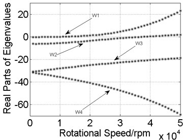
Before optimization, the relationship between rotational speed and the real parts of eigenvalues were given in Fig. 2. It can be seen from Fig. 2 that the real part of the natural frequency line W1 is greater than zero after the rotational speed is greater than 9000 rpm, which means the system is unstable; as for the natural frequency line W2, the unstable state will appear after the rotational speed is greater than 37500 rpm. The natural frequency lines W3 and W4 remain stable throughout the entire speed range. The above statement shows that the plain bearings bring stability problems to the rotor system. Therefore, the stability of the rotor system and the mass of the shaft were optimized in this paper, for the purpose of increasing the speed of each modal enters an unstable state, and reducing the mass of the shaft elements.
Fig. 2Real parts of the eigenvalues before optimization

The objective functions can be defined as:
where ωu is the minimum rotational speed of each modal enters unstable state, Wmax= 50000 rpm is the maximum rotational speed of the rotor system, m(X) represents the mass of entire shaft elements.
3.2. The design variables and constraints
The outer diameter of each shaft element was considered as the design variables:
wheredi is the outer diameter, and the constraints are:
The radial clearances of the plain bearings, c1 and c2, were also used as design variables due to their greater influence in rotor dynamics. The related parameters of the plain bearings are: the coefficient of kinetic viscosity is μ= 2.6502×10⁻² Pa·s, the effective length of bearing is L= 0.008 m. Before optimization, the radial clearances are c1=c2= 5×10⁻⁶ m, the mass of entire shaft elements is 5.4886 kg.
4. Results
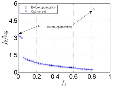
The relationship between the objective functions after optimization is shown in Fig. 3. f1 is the stability of rotor system, f2 is the mass of entire shaft elements. It can be seen that each individual result is better than original results, f1= 0.82 and f2= 5.4886.
Fig. 3Optimization results for complex rotor system

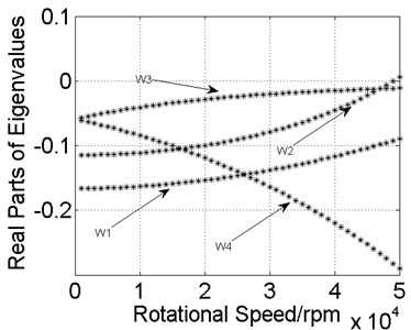
Fig. 4Real parts of eigenvalues for individual A

The real parts of eigenvalues for individual A in Pareto front is shown in Fig. 4. Individual A means that the stability is the best, whereas its mass is biggest. Individual A isn’t the most suitable choice in most cases for the designers, people still need to choose the only solution from the Pareto front. The simplest method is the reference point method [9]. There are many methods can be used to select suitable individual from the Pareto front. The reference point method is the only one of them. Deeply discussion of these methods is not the focus of this paper, so only the reference is listed here [10].
5. Conclusions
In this paper, the model of the rotor system was established by the finite element method, and the optimization of weight and stability for the rotor system was carried out by multi-objective genetic algorithm.
The research shows that:
1) Multiple optimal solutions can be given by NSGA-II algorithm, and there is no dominant relationship between any two individuals in these solutions. Therefore, a large number of alternatives can be provided through only one optimization in the rotor system design stage.
2) The stability of the rotor system with plain bearings and the weight of the shaft element had been successfully optimized, which improves the stability of the rotor system and greatly reduces the total mass of the rotor system.
References
-
Helfrich Reinhard, Wagner Nils Application of optimization methods in rotor dynamics. Proceedings of the 9th IFToMM International Conference on Rotor Dynamics, Vol. 21, 2015, p. 1715-1725.
-
Yang B. S., Choi S. P., Kim Y. C. Vibration reduction optimum design of a steam-turbine rotor-bearing system using a hybrid genetic algorithm. Structural and Multidisciplinary Optimization, Vol. 30, Issue 1, 2005, p. 43-53.
-
Lin Y., Cheng L., Huang T. P. Optimal design of complex flexible rotor-support systems using minimum strain energy under multi constraint conditions. Journal of Sound and Vibration, Vol. 215, Issue 5, 1998, p. 1121-1134.
-
Diewald W., Nordmann R. Dynamic analysis of centrifugal pump rotors with fluid mechanical interactions. Boston Proceedings of the 11th Biennial Conference on Mechanical Vibration and Noise, Vol. 111, Issue 4, 1987, p. 370-378.
-
Diewald W., Nordmann R. Parameter optimization for the dynamics of rotating machinery. Proceedings of the 3rd International Conference on Rotor Dynamics, 1990, p. 51-55.
-
Xu Jing Qi A survey of research on multi-objective optimization algorithms. Science and Technology Information, Vol. 32, 2010, p. 115-116.
-
Zhong Y. E., He Y. Z., Wang Z., et al. Rotor Dynamics. Tsinghua University Press, 1987, p. 177-178.
-
Lin Y. H., Lin S. C. Optimal weight design of rotor systems with oil-film bearings subjected to frequency constraints. Finite Elements in Analysis and Design, Vol. 37, Issue 10, 2001, p. 777-798.
-
Deb K., Sundar J., Bhaskara U., Chaudhuri S. Reference point based multi-objective optimization using evolutionary algorithms. International Journal of Computational Intelligence Research, Vol. 2, Issue 3, 2006, p. 635-642.
-
Miettinen K. M. Nonlinear Multiobjective Optimization. Springer, Kluwer, 1999.
-
Choi B. G., Yang B. S., Kim W. C. Optimum shape design of shaft using genetic algorithm. Proceedings of the 5th Asian International Conference on Fluid Machinery, 1997, p. 85-92.
