Abstract
Variation of film pressure was studied by short bearing hypothesis and differential method for grooving on film inner-face. The results were compared with those of FLUENT analysis. Then, effects of the position of groove were studied on film pressure and damping through differential method. The results shown that short bearing hypothesis cannot conform to the actual situation considering grooving. The effect of grooving on the pressure distribution of film was researched by differential method, and the results are consistent with the FLUENT simulation analysis. Side grooving has less effect on film pressure and damping, so it is recommended when the design and assembly conditions are allowed.
1. Introduction
Most of the faults of aero-engines are vibration faults. The possibility of faults in rotor support system will be increasing when the rotor is operating under high speed. The faults include large vibration, non-synchronized whirling and instability of the rotor system, even the fatigue fracture of the rotor shaft. They will seriously affect the performance and life of the aero-engines [1]. Squeeze film damper (SFD) is widely used in the rotor support of aero-engines due to its relatively simple structural design and obvious damping effect.
The design parameters of the squeeze film damper directly determine its damping effect. At present, the design method of the squeeze film damper is the trial method combining experience, theory and experiment. Ning Xu et al. [2, 3] derived the calculation formula of damping coefficient under different assumptions and used pulse excitation method to study the influence of structural parameters of squeeze film damper on the damping characteristics of marine gas turbine. Jiali Wang et al. [4] established the dynamic equation of the film damping and designed the tangential experimental device. The effect of the film thickness on the damping coefficient and the variation of the damping coefficient with the frequency were verified by experiments. Zhanchi Liu et al. [5, 6] designed a flexible rotor system that can change the film clearance separately and studied the effect of static eccentricity on the damping characteristics of the squeeze film damper. Ming Zhang et al. [7] studied the effects of the number of supply holes, the cross-sectional area of the supply hole, the size of the supply groove and the supply flow on the equivalent damping of the damper and the circumferential position damping through numerical simulation. DOUSTI et al. [8] used computational fluid mechanics software CFX to study the effects of supply groove and inlet pressure on the flow field characteristics of SFD. Xiangwei Zhao [9] established the Reynolds equation for squeeze film damper under static eccentricity, and theoretically analyzed the effects of end seal clearance and static eccentricity on film characteristics. ANDRES et al. [10, 11] studied the effects of SFD supply groove, static eccentricity and film end seal on the dynamic characteristics of SFD through two-way incentive test.
The paper is based on the structural parameters of a certain type of squeeze film damper and the effects of supply groove on characteristics of SFD were researched through short bearing hypothesis, differential method and FLUENT simulation. The results provide reference and basis for the design and use of SFD.
2. Supply groove effects on film pressure
We study an open-end squeeze film damper. The SFD model is shown in Fig. 1. The geometry and working parameters of this SFD are shown in Table 1.
Fig. 1The geometry of squeeze film damper (a half of whole SFD)
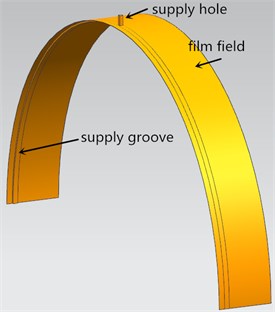
Table 1The geometry and working parameters of SFD
Film radius, | 135.05 mm | SFD length, | 33 mm |
Film clearance, | 0.15 mm | Precession frequency, | 100 Hz |
Eccentricity ratio, | 0.2 | Supply groove length | 3 mm |
Supply groove clearance | 1 mm | Inlet pressure | 0.1 MPa |
Inlet temperature | 40℃ | – | – |
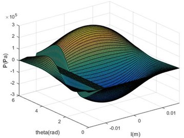
Whether using differential method or FLUENT to calculate, the model needs to be simplified. Its purpose is generally to improve the mesh quality or increase the nonlinear iterative convergence of the model. When using the differential method, the fillet is processed into a hypotenuse to avoid the Jacobi matrix singularity. The film pressure distribution was gained separately by short bearing hypothesis and differential method for the film inner-face with or without groove. The results were shown in Fig. 2 to Fig. 5.
Fig. 2Short bearing hypothesis (no groove)
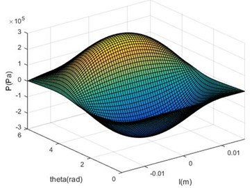
Fig. 3Short bearing hypothesis(groove)
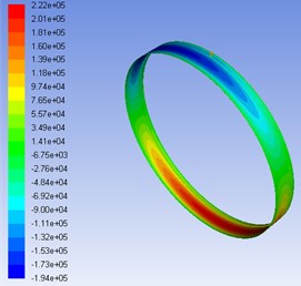
The fillet must be removed at the supply groove when modeling in the FLUENT calculation. Film pressure distribution is shown in Fig. 6.
Short bearing hypothesis was adopted for considering grooving, and the film pressure distribution was shown in Fig. 3. The result shows that the pressure at the groove is simply wiped out and the pressure distribution in the rest remains unchanged. Obviously, it is not in line with the actual situation. In Fig. 5, differential method was adopted for considering grooving. The pressure dropped locating in the groove. Grooving also affects global pressure distribution and makes overall pressure drop. The result is consistent with the FLUENT simulation analysis.
Fig. 4Differential method (no groove)
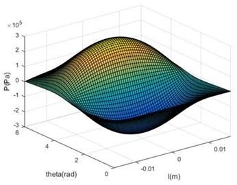
Fig. 5Differential method (groove)
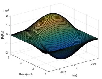
Fig. 6Film pressure distribution in FLUENT
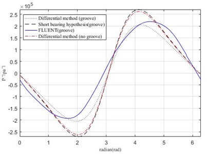
Film circumferential pressure of various solutions is shown in Fig. 7 with or without groove. It can be seen that only the influence of grooving on the film pressure distribution is real when using differential method, and its result is very close to the Fluent simulation result.
Fig. 7Comparison of various solutions
3. Supply groove positions effect on film
The position of supply hole locates directly above on the supply groove. The influence on film was studied by differential method under different positions of supply groove. Three positions were chosen: separately as center grooving, 1/4 position grooving and side grooving. The rest of the conditions are the same. The geometry and working parameters of SFD is the same as the previous section.
The film pressure and damping distribution of three positions is shown in Fig. 8 and Fig. 9.
The effect of supply positions on film pressure and damping is shown in Table 2 and Table 3.
There is a big gap among three different supply positions for the film pressure and damping. The results show that the scale from smallest to largest about position relationship was center supply < 1/4 position supply < side supply. The damping of the SFD decreased by 40 % for center supply comparing with non-groove. It is easy to explain the phenomenon according to the film pressure analysis.
The 50 % damping of damper is generated in the central area which is about 1/3 of the film width around the center line under normal conditions. So, we can think this 1/3 center area is the core area of the squeeze film damper. Grooving in this core area is bound to greatly weaken the damping of the squeeze film damping. On the contrary, grooving on the side where the film pressure is low has less influence on the film damping.
Fig. 8Effect of grooving positions on film pressure distribution (axial)
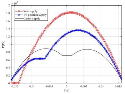
Fig. 9Effect of grooving positions on film pressure distribution (circumferential)
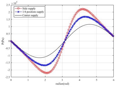
Table 2The effect of supply positions on film pressure
Supply position | Maximum pressure (105 Pa) | Decreasing percentage |
No groove | 2.61 | 0 % |
Center supply | 1.27 | 51.3 % |
1/4 position supply | 1.77 | 32.2 % |
Side supply | 2.23 | 14.6 % |
Table 3The effect of supply positions on film damping
Supply position | Film damping (104 N·S/m) | Decreasing percentage |
No groove | 11.31 | 0 % |
Center supply | 6.76 | 40.2 % |
1/4 position supply | 7.84 | 30.7 % |
Side supply | 8.95 | 20.9 % |
4. Conclusions
In this paper, short bearing hypothesis and differential method were used to study film pressure distribution. Meanwhile, the results were compared with FLUENT simulation. Differential method was used to study the influence of different positions of supply groove on film. The conclusions are summarized as follows:
1) The results of grooving can’t conform to the actual situation for short bearing hypothesis. It’s a convenient calculation method when there is no groove on the SFD.
2) The results of grooving are very close to the FLUENT simulation for differential method. The two methods can truly reflect film pressure distribution.
3) Side grooving has less effect on film pressure and film damping, so it is recommended when the design and assembly conditions are allowed.
References
-
Chen Zhao Research on Dynamic Characteristics Analysis Method of Elastic Support Squeeze Film Damper. Nanjing University of Aeronautics and Astronautics, Nanjing, 2008.
-
Xu Ning, Wang Xu, Zhang Min Experimental study on damping characteristics of marine gas turbine squeeze film damper. Thermal Power Engineering, Vol. 27, Issue 1, 2012, p. 13-17.
-
Liu Zhansheng, Zhang Min, Xu Facheng Experimental study on finite-length squeeze film damper based on opening at both ends. Vibration and Shock, Vol. 31, Issue 18, 2012, p. 137-142.
-
Wang Jiali, Zhang Guangpeng, Wang Liyu Experimental study on tangential film damping. National Structural Engineering Conference, 2017.
-
Liu Zhanchi, Liao Mingfu, Cong Peihong Influence and control method of static eccentricity on anti-vibration performance of squeeze film damper rotor. Machinery and Electronic, Vol. 34, Issue 5, 2016, p. 49-54.
-
Liu Zhanchi, Liao Mingfu, Cong Peihong Experimental study on influence of static eccentricity on damping characteristics of squeeze film damper. Propulsion Technology, Vol. 37, Issue 8, 2016, p. 1560-1568.
-
Zhou Hailun, Zhang Ming, Cheng Xiaoming Effect of supply conditions on equivalent damping and circumferential position damping of squeeze film damper. Journal of Mechanical Engineering, Vol. 54, Issue 6, 2018, p. 215-223.
-
Dousti S., Gerami A., Dousti M. A numerical CFD analysis on supply groove effects in high pressure, open end squeeze film dampers. International Journal of Engineering Innovation and Research, Vol. 5, Issue 1, 2016, p. 80-89.
-
Zhao Xiangwei Study on Dynamic Characteristics of Squeeze Film Damper under Static Eccentricity. Nanjing University of Aeronautics and Astronautics, Nanjing, 2018.
-
Andres L. S. Force coefficients for a large clearance open ends squeeze film damper with a central feed groove: experiments and predictions. Tribology International, Vol. 71, Issue 1, 2014, p. 17-25.
-
Andres L. S., Seshagiri S. Damping and inertia coefficients for two end sealed squeeze film dampers with a central groove: measurements and predictions. Journal of Engineering for Gas Turbines and Power, Vol. 135, Issue 11, 2013, p. 112503-1-9.

