Abstract
This study proposes a three-dimensional vibration model of bus with 10 DOF (degree of freedom) based on Dragan Sekulić model to analyze the suspension parameters directly influenced ride comfort. The suspension parameters which include the stiffness and damping parameters are analyzed based on the weighted r.m.s. (root-mean-square) acceleration responses of the space of a driver, passenger in the middle part of the bus and passenger in the rear overhang according to ISO 2631-1:1997. The results show that both stiffness and damping parameters of vehicle suspension have important influences on ride comfort. Especially, the stiffness and damping values of vehicle suspension are within the value ranges (0.5k0 ≤ k ≤ 0.75 k0) and (0.5c0 ≤ c ≤ 0.75c0) to improve the ride comfort of driver and passengers.
1. Introduction
Suspension system is one of the important components to connect a vehicle body and its wheel, which not only affects the vehicle ride comfort, but also has the negative effects on the road surface as well as safe driving. Parameters matching, and optimization of suspension system are an important approach to improve vehicle ride comfort. In order to improve the ride comfort, road holding, workspace and preventing rollover, the method for the optimized design of the vehicle suspension system, considering a full vehicle model with 11-DOF based on the vertical acceleration values of seats was presented [1] and the optimal parameters of passive suspension system was found to improve ride comfort and rollover resistance including safety of the vehicle design. The MatLab/Simulink model of 7-DOF full vehicle model was developed and a genetic algorithm optimization technique was used to find the optimum values of spring stiffness and damping coefficient for front and rear passive suspension system at variable velocities which improve the vehicle ride performance [2]. The optimal parameters of passive and semi-active suspension systems using the Pareto front optimization method in respect with ride comfort and road holding were presented [3]and the active control strategy was applied to the full-bus suspension system to improve ride comfort [4]. The bus spatial vibration model with 10-DOF was developed to analyze the effects of vibrations on vehicle ride comfort and the analytical results have shown that the allowable vibration exposure time for the driver’s body decreases as the spring stiffness of the driver’s seat suspension system increases [5].
The evaluation method based on passenger crowdsourcing mode was proposed, which can fully perceive the vibration signals in different positions in the bus and indicate the vibration comfort in real time [6]. The domestic vehicle was chosen as the research object which 2-DOF vibration model was established according to the vehicle dynamics theory [7]. Then, the root mean square value of each vibration response was calculated by MatLab software when vehicle moves on grade C road surface and the study results indicate that the influence rule of each parameter of suspension on the vehicle ride comfort was obtained.
A full-vehicle vibration model with 10 DOF for 2-axle bus considering air suspension systems and seat suspension systems was established based on Dragan Sekulić model [5]. Vibration differential equations and MatLab, Simulink model is established to simulate for full-vehicle vibration model with the random road surface profile according to the international standard ISO 8068 [8]. The influences of vehicle suspension parameters such as stiffness and damping coefficients on seat’s driver/passenger comfort is analyzed according to the international standard ISO 2631-1 (1997) [9].
2. Bus vibration model
A bus IK-301 with the dependent suspension systems including an air bag and two air bags for front and rear suspension systems was selected for establishing vehicle vibration model. And the vibration model with 10-DOF was established by Dragan Sekulić [5] to analyze the seat comfort of bus IK-301, as shown in Fig. 1.
Fig. 13-D dynamic model of the bus IK-301
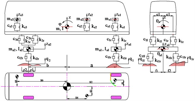
Fig. 1, kij are the single air bag stiffness coefficients; cij are the single shock-absorber damping coefficients; ktkj are the single tire stiffness coefficients; ctkj are the single tire damping coefficients; m are the elastic-suspended mass of the fully loaded bus; ma1 and ma2 are the front and rear axle mass; msi are the mass of the driver and seat, mass of the passenger 1 and seat and mass of the passenger 2 and seat; aand b are the distances from the front and rear axles to the bus center of gravity; sn, rk, fk and ek are the distances, respectively; φ, θ and θak are the angular displacements at the center of gravity of the elastic-suspended mass of the fully loaded bus and axles, respectively; I and Iak are the moments of inertia of the elastic-suspended mass of the fully loaded bus and axles, respectively; qkj are the random road surface profiles; v is the speed of vehicle (i= 1, 2, 3, k= 1, 2 and n= 1/6 and j= left, right).
The vehicle vibration equations can be formulated in different ways. One of the most popular methods is the Lagrange equation type II. For the vibration model showed in Fig. 1, the general vibration differential equation for the bus IK-301 is represented as the standard form of matrix equation:
where, m, k and c indicate the mass matrix, stiffness matrix and damping matrix of vehicle and seats, respectively; the ¨z, ˙z and z respectively refer to the acceleration, velocity, displacement vectors of vehicle and seats; Ft=kt{q}+ct{˙q}, is the vector of wheel-road contact forces, where kt and ct indicate the tire stiffness matrix and tire damping coefficient matrix of wheels, respectively, q is the random road excitation vector.
3. Random road surface excitation
There are two main methods for obtaining the random road surface excitation such as experimental measurement and numerical simulation using a time-domain model. In this study, the random road surface excitation is depicted by numerical simulation method [10]. Road profile is typically assumed to be homogeneous and isotropic Gaussian random process and its statistical characteristics can be described by PSD. According to the International Standards Organization (ISO) 8608 [8], PSD of road roughness can be defined as Eq. (2):
where, n is spatial frequency in m-1, n0 is reference spatial frequency with a value of 0.1 m-1, Gq(n0) is PSD value for reference spatial frequency in m3, w is termed waviness, and reflects approximate frequency structure of the road profile, commonly taken as w= 2.
Eq. (2) leads to estimation errors (overrated phenomenon) especially at low frequencies. To deal with this problem, PSD of road roughness based on rational white noise signal is proposed [10, 11], and Eq. (2) can be modified as follows:
where, v represents velocity of the vehicle in m/s, ρ2 represents variance of road roughness.
Time domain representation of the road can be given as:
where, q(t) is the random road excitation; w(t) is the white noise sequence.
Simulink of MatLab can be used to solve the process described by Eq. (4) to generate random road profiles, the entry of the process is the standard deviation of the white noise process which depends of the road surface category, a 80 km/h-22,2 m/s speed and other parameter values [12] are set. Simulink model of random road generator is shown in Fig. 2(a) and the simulation result of the typical grade B road surface is shown in Fig. 2(b).
Fig. 2Simulink model of random road generator and simulation result
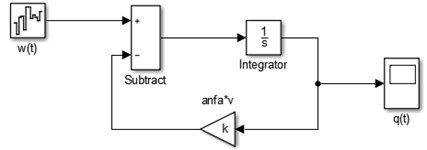
a) Simulink model of random road generator
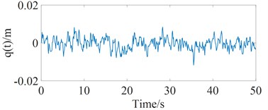
b) Grade B road profile
4. Vehicle ride comfort evaluation method
Currently there are many methods to evaluate the vehicle ride comfort such frequency-domain method, time-domain method. This study is based on ISO 2631-1 (1997), the vibration evaluation based on the basic evaluation method including measurements of the weighted root-mean-square (r.m.s.) acceleration is defined by:
where, aw(t) is the weighted acceleration (translational and rotational) as a function of time, m/s2; T is the duration of the measurement, s.
In this way, a synthetic index-called vertical weighted rms acceleration, awz can be calculated from formula Eq. (5) and the rms. value of the vertical acceleration in vehicle would be compared with the values in Table 1, for indications of likely reactions to various magnitudes of overall vibration in the public transport.
Table 1Comfort levels related to aw threshold values
aw / (m.s2) | Comfort level |
< 0.315 | Not uncomfortable |
0.315/0.63 | A little uncomfortable |
0.5/1.0 | Fairly uncomfortable |
0.8/1.6 | Uncomfortable |
1.25/2.5 | Very uncomfortable |
> 2 | Extremely uncomfortable |
5. Simulation and analysis results
In this study, MatLab software and Simulink toolbox are selected to solve Eq. (1) with the vehicle simulation parameters [5] and the random road surface excitation. The simulations are carried out when vehicle moves on the ISO good road (grade B) condition and the bus speed of 22,2 m/s with full load. The vertical acceleration responses of the space of a driver, passenger in the middle part of the bus and passenger in the rear overhang is shown in Fig. 3.
The value of aws1 is defined as 0.199 m.s-2 and this value of aws1 satisfies the conditions for driver comfort (according to Table 1); the values of aws2 and aws3 are defined as 0.621 m.s-2, 0.685 m.s-2, respectively and this values satisfy uncomfortable conditions for passengers (according to Table 1). Both stiffness and damping parameters of vehicle suspension have important influences on vehicle ride comfort. In order to analyze the influence of bus suspension parameters such as stiffness and damping coefficients on ride comfort, discussions will present in the following section.
Fig. 3The vertical acceleration responses of bus seats
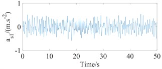
a) The space of a driver
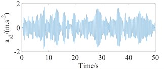
b) Passenger in the middle part
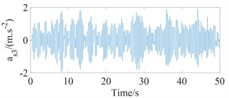
c) Passenger in the rear overhang
5.1. Influence of vehicle suspension stiffness
Vehicle suspension stiffness is an important factor that influences the ride comfort. To analyze its effect on the aws1, aws2 and aws3 values, the values of suspension stiffness coefficients k=[0.250.50.7511.251.51.752.0]×k0, where k0=[k1r,k1l,k2r,k2l]T and the values of suspension damping coefficients c=[0.250.50.7511.251.51.752.0]×c0, where c0=[c1r,c1l,c2r,c2l]T were analyzed when vehicle moves on the ISO good road (grade B) condition and the bus speed of 22,2 m/s with full load, where k0 and c0 are used to designate the vehicle stiffness and damping coefficients in the reference document [5]. The influence of vehicle suspension stiffness coefficients on aws1, aws2 and aws3 values are shown in Fig. 4.
From Fig. 4 shows that when the vehicle suspension stiffness coefficient increases, the aws1, aws2 and aws3 values tend to increase, which makes the negative effects on ride comfort of driver and passengers. The aws1 values increase quickly when the values of the damping coefficients are c= 0.25c0 and the aws1, aws2 and aws3 values do not change much when the values of the damping coefficients are achieved by great values. When the values of the damping coefficients increase from 1.5c0 to 2c0, the aws1, aws2 and aws3 values decrease about from 3.6 to 3.76 %, which makes the ride comfort of driver and passengers negligible.
Fig. 4Influence of vehicle suspension stiffness coefficients on ride comfort of bus seats
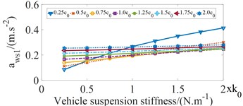
a) The aws1 values at vertical driver's seat
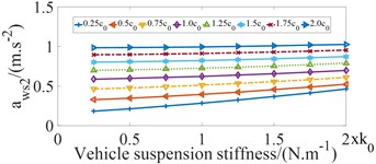
b) The aws2 values at passenger in the middle part
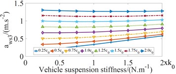
c) The aws3 values at passenger in the rear overhang
5.2. Influence of vehicle suspension damping
Vehicle suspension damping is another important factor that influences the ride comfort. To analyze its effect on the aws1, aws2 and aws3 values, the values of suspension damping coefficients c=[0.250.50.7511.251.51.752.0]×c0, where c0=[c1r,c1l,c2r,c2l]T and the values of suspension stiffness coefficients k=[0.250.50.7511.251.51.752.0]×k0, where k0=[k1r,k1l,k2r,k2l]T were analyzed when vehicle moves on the ISO good road (grade B) condition and the bus speed of 22,2 m/s with full load. The influence of vehicle suspension damping coefficient on aws1, aws2 and aws3 values are shown in Fig. 5.
Fig. 5Influence of vehicle suspension damping coefficient on ride comfort of bus seats
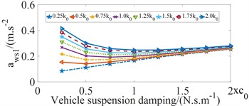
a) The aws1 values at vertical driver's seat
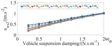
b) The aws2 values at passenger in the middle
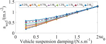
c) The aws3 values at passenger in the rear overhang
Fig.5 shows that vehicle suspension damping coefficient increases from 0.25 to 0.75c0, the aws1 values tends to decrease, which makes driver’s ride comfort considerably improve. And then the aws2 and aws3 values tends to increase quickly, which has the negative effects on ride comfort of passengers.
According to Fig. 4 and Fig. 5, in order to decrease the vehicle vibrations and hence improve the ride comfort, the values of the vehicle suspension parameters are within the value ranges (0.5k0 ≤ k ≤ 0.75k0) and (0.5c0 ≤ c ≤ 0.75c0).
6. Conclusions
This study presents a methodology to analyze the effects of bus suspension parameters on ride comfort based on the full-vehicle vibration model using the random road surface profile and the analysis results as follow:
1) In the suspension system, the reasonable matching of suspension stiffness and damping can efficiently improve seat ride comfort, which keeping ride comfort keeping ride comfort within a safety limits and the safety of the road surface.
2) In order to decrease the vehicle vibrations and hence improve the ride comfort, the values of the vehicle suspension parameters are within the value ranges (0.5k0 ≤ k ≤ 0.75k0) and (0.5c0 ≤ c ≤ 0.75c0).
References
-
Seifi Abolfazl, Hassannejad Reza, Hamed Mohammad A. Optimum design for passive suspension system of a vehicle to prevent rollover and improve ride comfort under random road excitations. Proceedings of the Institution of Mechanical Engineers, Part K: Journal of Multi-body Dynamics, Vol. 230, Issue 4, 2015, p. 426-441.
-
Geweda A. E., El Gohary M.-A., El Nabawy A.-M., Awad T. Improvement of vehicle ride comfort using genetic algorithm optimization and PI controller. Alexandria University Alexandria Engineering Journal, 2017, Vol.56, p. 405-414.
-
Koulocheris Dimitrios, Papaioannou Georgios, Chrysos Emmanouil A comparison of optimal semi-active suspension systems regarding vehicle ride comfort. IOP Conference Series: Materials Science and Engineering Vol. 252, 2017, p. 012022.
-
Mujde Turkkan, Nurkan Yagiz Fuzzy logic control for active bus suspension system. Journal of Physics: Conference Series, Vol. 410, 2013, p. 0012006.
-
Sekulic Dragan, Dedovic Vlastimir, Rusov Srdjan, Šalinic Slaviša, Obradovic Aleksandar Analysis of vibration effects on the comfort of intercity bus users by oscillatory model with ten degrees of freedom. Applied Mathematical Modelling, Vol. 37, 2013, p. 8629-8644.
-
Zhao Hong, Guo Li Lu, Zeng Xiang Yan Evaluation of bus vibration comfort based on passenger crowdsourcing mode. Mathematical Problems in Engineering, Vol. 2016, 2016, p. 2132454.
-
Zhang G. X., Dong Y. E. Study on the influence of suspension parameters on the vehicle ride comfort, Journal of Shaanxi University of Science and Technology (Natural Science Edition), Vol. 5, 2016, p. 147-151.
-
ISO 8068. Mechanical Vibration-Road Surface Profiles-Reporting of Measured Data. International Organization for Standardization, 1995.
-
ISO 2631-1. Mechanical Vibration and Shock-Evaluation of Human Exposure to Whole-Body Vibration, Part I: General Requirements. The International Organization for Standardization, 1997.
-
Wang Zhen Feng, Dong Ming Ming, et al. Influence of road excitation and steering wheel input on vehicle system dynamic responses. Applied Sciences, Vol. 7, Issue 6, 2017, p. 570-579.
-
Dodds C. J., Robson J. D. The description of road surface roughness. Journal of Sound and Vibration, Vol. 31, Issue 2, 1973, p. 175-183.
-
Quynh Le Van Vibration Study and Control Cab of Vibratory Roller. Southeast University, Nanjing, China, 2013.
