Abstract
This study presents a method to improve vehicle ride comfort using additional damping coefficient values for an internal combustion engine (ICE) rubber mounting system. To analyze the effect of the adding damping coefficient values into the rubber mounting system on vehicle ride comfort, a full-vehicle vibration model with 10 degrees of freedom is established under the combination of road surface roughness and ICE excitations. The damping coefficient values are added into ICE rubber mounting system which are respectively analyzed and evaluated according to the international standard ISO 2631-1 (1997). The study results do not only evaluate the influence of the adding damping coefficients on vehicle ride comfort but also suggest the optimal design solution for ICE mounting system to improve vehicle ride comfort.
Highlights
- A full-vehicle vibration model including engine vibration
- The combination of road surface roughness and engine excitations
- Rubber engine mount
- Hydraulic engine mount
- Vehicle ride comfort
1. Introduction
An engine rubber mounting is one of the important parts of a vehicle. It is a function to isolate or absorb and to reduce vibration to the vehicle body and the passenger. The concurrent engineering approach using the integration of TRIZ, morphological chart, and ANP methods approach was applied in the development of the conceptual design for the polymer composites automotive engine rubber mount component [1]. To reduce vibration and noise for heavy-duty trucks, the Genetic Algorithm (GA) method was adopted for the Powertrain Mounting System (PMS) optimization [2]. To improve the vibration isolation ability of the powertrain mounting system, considering the powertrain of front wheel drive car as the research object, the vibration decoupling rate and its corresponding frequency of the powertrain mounting system are analyzed by rigid body dynamics and energy method. The results show that the vibration isolation performance has been significantly improved more than 10 % [3]. The study proposes new setups in the suspension systems, including springs, shock absorbers and rubber mountings of the engine system to improve the passengers’ comfort levels. The combination of different sets of rubber mountings, springs, and shock absorbers were tested. The changes proposed in the study are analyzed in sequence and based on the results, the best combination is proposed [4]. Dynamic design and vibro-acoustic modelling issues for automotive structures are illustrated via two case studies: (1) the role and performance of passive and adaptive hydraulic engine mounts and (2) the importance of welded joints and adhesives in vehicle bodies and chassis structures which is highlighted via generic ‘T’ and ‘L’ beam assemblies [5]. The review on internal combustion engine vibrations and mounting systems are presented and analyzed in the references [6, 7]. For a better description of the characteristics of the vehicle engine shake performance, a full vehicle model with 14 degree of freedoms (DOFs) with hydraulic engine mounts (HEMs) was established to evaluate the effect of the HEM on the engine shake performance by comparing the results obtained from the known 13 DOF model [8]. However, in most studies full vehicle dynamic models do not consider the effects of ICE vibrations on vehicle ride comfort [10-13], or if there is, they only consider the effects of ICE vibrations themselves [9]. The major goal of this study is to establish a full-vehicle vibration model with 10 degrees of freedom under two combinations from the random road surface roughness according to the International Standards Organization (ISO) 8608 [15] and ICE excitations. The damping coefficient values are added into ICE rubber mounting system which are respectively analyzed and evaluated vehicle ride comfort according to the international standard ISO 2631-1 (1997) [16].
2. Vehicle dynamic model
2.1. Full vehicle dynamic model
Many studies indicate that the vertical, pitch and roll angles of engine and vehicle body have the greatest impact on vehicle ride comfort, so a three-dimensional full-vehicle dynamic model with 10 degrees of freedom is established to evaluate influence of the adding damping coefficients into engine rubber mounting system on vehicle ride comfort, as shown in Fig. 1.
Fig. 1Three-dimensional dynamic model of full vehicle
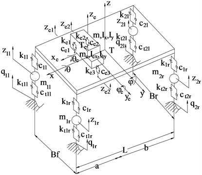
In Fig. 1, and are the stiffness and damping coefficients of the tires, respectively; and are the stiffness and damping coefficients of the suspension systems of vehicle, respectively; and , are engine rubber mounting system, respectively; and are the unsprung mass of vehicle, respectively; are the sprung mass of the vehicle body; are the mass of IC engine; , and , are the mass moment of inertia of vehicle body and cutout IC engine; , , and are the vertical displacements of the axles, vehicle body and cutout IC engine, respectively; , and; , are the pitch and roll angle displacements of the vehicle body and cutout IC engine, respectively; , , , , are the distances (1-2; left, right, 1-3).
Equations of motion: The equations of vehicle motion can be formulated in different ways such as Lagrange’s equation, Newton-Euler equation, Jourdain’s principle. A combined method of the multi-body system theory and D’Alembert’s principle is chosen for this study. The equations of motion for IC engine are written as follows:
where, , is the distances between the front mounts and the centre of gravity (CG). The equations of motion for vehicle axles and body are written similarly.
2.2. Determining the vertical force of IC engine mounting
Rubber mounting system is widely used to isolate the IC engine vibrations, which is very useful to reduce the vibration and noise in high excitation frequencies. However, the damping coefficient value of a rubber mounting is very small to reduce the IC engine vibrations in low excitation frequencies. To improve vehicle ride comfort in low excitation frequencies, the hydraulic passive damping coefficient values are added to ICE rubber mounting system. A rubber mounting in the vertical direction can be modeled as a lumped parameter model with internal friction damping coefficient and hydraulic passive damping coefficient as shown in Fig. 2.
The schematic of a lumped parameter model with internal friction damping coefficient is shown in Fig. 2(a). The vertical forces of the IC engine mounting system is defined as:
The schematic of a lumped parameter model with adding hydraulic passive damping coefficient is shown in Fig. 2(b). The vertical forces of the IC engine mounting system is defined as:
Fig. 2Lumped parameter model of IC engine mounting system
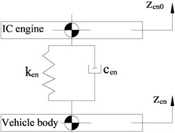
a) Lumped parameter model with internal friction damping coefficient
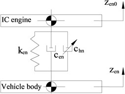
b) Lumped parameter model with adding hydraulic passive damping coefficient
2.3. Analysis of vibration excitation source
2.3.1. Road surface excitation
To evaluate the effect of the addition of hydraulic damping coefficient into engine rubber mounting system on vehicle ride comfort, the road surface roughness is road excitation which is simulated in space domain and acts as an input to the vehicle-road model. In this study, the road surface roughness is simulated according to the International Standards Organization (ISO) 8608 [15]. A road surface roughness is usually assumed to be a zero-mean stationary Gaussian random process and can be generated through an inverse Fourier transformation based on a power spectral density (PSD) function [14]. The road surface roughness is generated as the sum of a series of harmonics:
where, the spatial frequency range, , is divided into several uniform intervals which have a width of ; is PSD function (m3/cycle/m) for the road surface elevation, the power density in every small interval is substituted by where (1, 2,..., ) is center frequency among its intervals; is the wave number (cycle/m); is the random phase uniformly distributed from 0 to 2.
2.3.2. Force and torque excitations from IC engine
The engine is supported by three mounts arranged vertically and both the foundation and the engine are assumed to be rigid, the foundation has a large mass and the mount mass is ignored, as shown in Fig. 1. The vertical inertia force due to the reciprocating mass of the engine, the roll and pitch excitation moments of the engine [9] are defined as:
where, is the reciprocating mass of a piston, is the radius of a crank, is the ratio of to the length of the shaft, is the rotational frequency of the crank, is the distance between the CG and the centre-line of the second and third cylinders, is mean value of torque.
3. Results and discussion
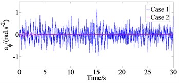
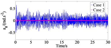
In order to analyze the effect of the different damping coefficient values of the mounting system on vehicle ride comfort, the mathematical model of the proposed full vehicle dynamic model with 10 degree of freedoms (DOFs) is developed in the MATLAB/Simulink to solve the vehicle differential equations in Section 2 with a set of parameters of original ICE engine and vehicle by the references [17]. The simulation results of the time domain responses of the vehicle body vertical, pitch angular, roll angular accelerations with road excitation when vehicle move on the ISO road surface class B at vehicle speed 20 m/s and engine speed 3200 prm (Case 1) and without road excitation when engine operates at speed 3200 rpm and vehicle speed 0 m/s (Case 2) are shown in Fig. 3.
Fig. 3The vehicle body vertical, pitch angular, roll angular accelerations with two cases
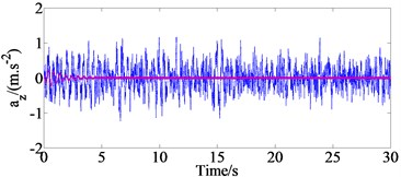
a) Vertical acceleration
b) Pitch angular acceleration
c) Roll angular acceleration
From the results of Fig. 3, we could be determined the values of the weighted root-mean-square (r.m.s.) accelerations of the vertical (), pitch () and roll () vehicle body are 0.039 m/s2, 0.021 rad/s2 and 0.018 rad/s2, respectively with case 2 and 0.355 m/s2, 0.266 rad/s2 and 0.155 rad/s2, respectively with case 1. The ICE excitations make the values of , and increase by 10.9 %, 7.9 % and 11.6 % and that means that the effects of the ICE excitations on the vehicle ride quality is relatively large.
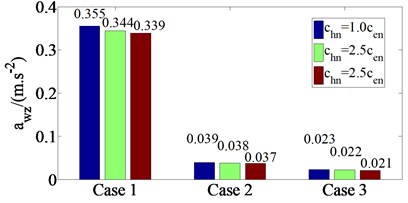
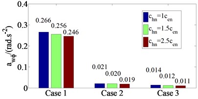
The hydraulic passive damping coefficient values () are added into ICE rubber mounting system, the , and values for three different damping coefficients , 1.5, and 2.5 (where are the damping coefficient of rubber mounting system in the design parameters of the original IC engine [17] were analyzed when engine and vehicle operate under different conditions such as case 1, case 2 and case 3 ( at engine idle speed 780 prm). The , and values for three different damping coefficients with case 1, case 2 and case 3 are shown in Fig. 4.
The results are shown in Fig. 4, indicating that as values into IC engine rubber mounting system increase, the , and values decrease. When values increase from 1 to 1.5 and then to 2.5, the , and values decrease from 3.1 to 11.6 %, 3.9 to 7.5 % and 6.8 to 14.8 % with case 1, from 2.6 to 5.4 %, 5.0 to 10.5 % and 5.9 to 12.5 % with case 2 and from 4.5 to 9.5 %, 16.7 to 27.3 % and 9.1 to 20.0 % with case 3. It means that the vehicle ride comfort is improved significantly, especially in case of engine idle speed 780 prm. However, the value of IC engine mounting system increases beyond the limit, which makes vehicle ride comfort decrease significantly.
Fig. 4awz, awϕ and awθ values for three different damping coefficients with three cases
a) At vertical motion of vehicle body
b) At pitch motion of vehicle body
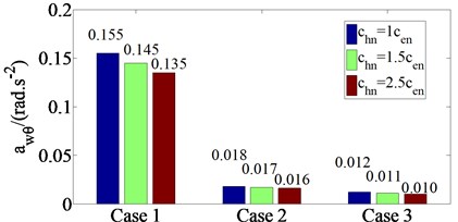
c) At roll of vehicle body
4. Conclusions
In this study, a full dynamic model with 10 degrees of freedom including engine vibrations is developed for analyzing the effect the addition of damping coefficient into engine rubber mounting system on vehicle ride comfort when engine and vehicle operate under three cases. The major conclusions that can be drawn from the analysis can be summarized as follows: (1) The ICE excitations have influence on the vehicle ride quality, which make the values of , and increased by 10.9 %, 7.9 % and 11.6 % in comparison with case 2. (2) the , and values decrease from 3.1 to 11.6 %, 3.9 to 7.5 % and 6.8 to 14.8 % with case 1, from 2.6 to 5.4 %, 5.0 to 10.5 % and 5.9 to 12.5 % with case 2 and from 4.5 to 9.5 %, 16.7 to 27.3 % and 9.1 to 20.0 % with case 3 when values increase from 1 to 1.5 and then to 2.5. The study results are the theoretical basis for optimizing the design of the ICE mounting system which will be published in the future by the authors.
References
-
Azammi A. M. N., Sapuan S. M., Ishak M. R., Sultan M. T. H. Conceptual design of automobile engine rubber mounting composite using TRIZ-Morphological chart-analytic network process technique. Defence Technology, Vol. 14, Issue 4, 2018, p. 268-277.
-
Zheng Li-Feng, Wang Tie, Li Guo-Xing Vibration and noise analysis of heavy-duty trucks based on powertrain lightweighting. Journal of Vibroengineering, Vol. 19, Issue 6, 2017, p. 4573-4590.
-
Xu Xiangyang, Su Chengyun, Dong Peng, Liu Yanfang, Wang Shuhan Optimization design of powertrain mounting system considering vibration analysis of multi-excitation. Advances in Mechanical Engineering, Vol. 10, Issue 9, 2018, p. 1-12.
-
Felipe L. M., Duarte M. L. M., Gutierrez J. C. H., Almeida U. S. Optimization of the vibrational comfort of passenger vehicles through improvement of suspension and engine rubber mounting setups. Shock and Vibration, Vol. 2018, 2018, p. 9861052.
-
Singh R. Dynamic design of automotive systems: Engine mounts and structural joints. Sadhana, Vol. 25, Issue 3, 2000, p. 319-330.
-
Ramachandran T., Padmanaban K. P. Review on internal combustion engine vibrations and mountings. International Journal of Engineering Sciences and Emerging Technologies, Vol. 3, 2012, p. 63-73.
-
Yu Y., Naganathan N. G., Dukkipati R. V. A literature review of automotive vehicle engine mounting systems. Mechanism and Machine Theory, Vol. 36, Issue 1, 2001, p. 123-142.
-
Guo Rong, Gao Jun, Wei Xiaokang Influence of hydraulic engine mounts on engine shake based on full vehicle model. Vibroengineering Procedia, Vol. 10, 2016, p. 376-381.
-
Li R., Chen W. M., Liao C. R. Hierarchical fuzzy control for engine isolation via magnetorheological fluid mounts. Proceedings of the Institution of Mechanical Engineers, Part D: Journal of Automobile Engineering, Vol. 224, Issue 2, 2009, p. 175-187.
-
Le V. Q. Comparing the performance of suspension system of semi-trailer truck with two air suspension systems. Vibroengineering Procedia, Vol. 14, 2017, p. 220-226.
-
Le Xuan Long, Tran Thi Hong, Le Van Quynh, Bui Van Cuong Performance analysis of the hydro-pneumatic suspension system of heavy truck. International Journal of Mechanical Engineering and Technology, Vol. 9, Issue 13, 2018, p. 1128-1139.
-
Le V. Q., Zhang J., Liu X., Wang Y. Nonlinear dynamic analysis of interaction between vehicle and road surfaces for 5-axle heavy truck. Journal of Southeast University, Vol. 27, Issue 4, 2011, p. 405-409.
-
Le Xuan Long, Le Van Quynh, Bui Van Cuong Study on the influence of bus suspension parameters on ride comfort. Vibroengineering Procedia, Vol. 21, 2018, p. 77-82.
-
Dodds C. J., Robson J. D. The description of road surface roughness. Journal of Sound and Vibration, Vol. 31, Issue 2, 1973, p. 175-183.
-
ISO 8068. Mechanical Vibration-Road Surface Profiles-Reporting of Measured Data. International Organization for Standardization, 1995.
-
ISO 2631-1. Mechanical Vibration and Shock-Evaluation of Human Exposure to Whole-Body Vibration, Part I: General Requirements. The International Organization for Standardization, 1997.
-
Hoang Anh Tan Study on the Effects of ICE Vibrations on Vehicle Ride Comfort. Master of Science thesis, University of Transport and Communications, Hanoi, Vietnam, 2015.
Cited by
About this article
The work described in this paper was supported by Thai Nguyen University of Technology for a scientific project (Code: T2017-B29).
