Abstract
The problem of transmission error is nowadays a very discussed topic in the field of vibration and noise generation. When tooth designing the numerical simulations can be used to minimize the transmission error, which fundamentally influences the gearbox behavior. For this purpose, a parametric model of straight tooth spur was developed. Subsequently, a calculation approach was used using the finite element method to determine the static error of the transmission at various load states, axial distance variations, and tooth shape elevation modifications. Based on the obtained results, it is possible to find a suitable type of tooth for the given operation conditions.
1. Introduction
The main purpose of gears is to transform the power from one shaft to another. The transmission is carried out via contact of tooth profile. The tooth type is chosen based on the drive and driven shaft, operation conditions, requirements on smooth running and also production costs. With increasing standard of living the comfort of machines operator and drivers is solved. The noise emitted from the machinery affect not only operator but also people which are in the immediate vicinity. With increasing number of machinery, the operation limits had to be established and then with advanced technological level is getting stricter. In several applications the gearboxes are one of the key component from point of view of noise source. The gearbox housing is excited based on the functional principle of gears contact. The transmission can be evaluated based on the several approaches at different phase.
First at the designing phase, the gearbox housing, shafts, bearing and gears are designed. Based on the numerical simulation by using finite element method (FEM) the optimization of component is performed, at different level. The basic level is modal properties of housing shafts and gears, but the functional principle of the whole transmission is not considered. The next level is harmonic analysis, where the knowledge about force location and value can be used.
The static structure analysis is performed for all components and the gearbox housing has to be designed to fulfil stiffness requirements. If the gearbox housing optimization is done, the gears modification can take place. The evaluation of two different gears modification can be done based on the transmission error. Two kinds of transmission errors are recognized, static transmission error (TE) and dynamic transmission error (DTE), where the moment of inertia plays important role. The TE can be calculated by using FEM [1-3], where different modification of spur gears can be compared.
The highest level of numerical simulation is combination of FEM and multibody simulations (MBS), where the functional principle of transmission is incorporated. The FEM is used to calculate input parameters into MBS. This approach is used in [4-6]. The sensitivity study can be performed based on the different parameters – input torque [4], damage of tooth [5]; or the special state can be investigated as rattle phenomenon [6]. To be able to perform MBS simulation the stiffness of gear contact has to be calculated.
Consequently, when the transmission is manufactured, the technical experiment can be performed to see, if the final design fulfils requirements. The static loading, the lifetime testing, the vibration and acoustic measurements are some of the most common tests. When the testing loop is created, the transmission error can be measured as well. The approach to measuring and data processing is mentioned in [7].
2. Methods
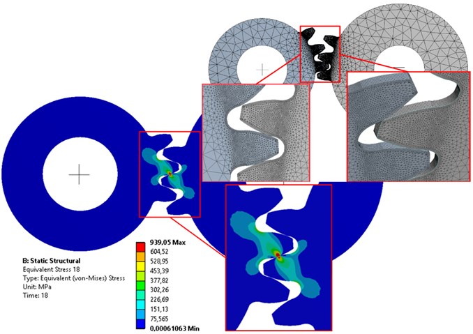
First the parametric CAD model of spur gear was created to enable easy modification of basic gear parameters. The spur gears model enables to solve 3D model with 1 mm thickness. This simplification significantly affects computational time. The TE is solved on the spur gear with module 3 mm, number of teeth 20 and 25, angle of tooth engagement 20 deg and diameter of pitch circle 60 mm, respectively 75 mm. Afterwards the Ansys Workbench was used to set contact analysis. The simplified model of gears is shown on the Fig. 1.
First the sensitivity study was performed, see Table 1. The effect of element size at the critical point was monitored. The difference of Von Mises stress and computation time was noticed. The element size has a notable effect on the maximum value of stress, but very small effect on the TE, see Fig. 2. On the other hand, the element size must be small enough to describe the design modification, for that reason the 0.1/0.1 variant is used.
Table 1Sensitivity study of element size with focused on von Mises stress
Element size evolvent / trochoid | Number of nodes | Number of elements | Von Mises stress [MPa] | Computational time [hours] |
0.1 / 0.1 | 254 483 | 130 631 | 973.46 | 19.5 |
0.1 / 0.2 | 178 048 | 88 604 | 988.97 | 12 |
0.2 / 0.1 | 160 381 | 80 521 | 979.65 | 11 |
0.15 / 0.1 | 192 716 | 97 934 | 939.05 | 12.5 |
Fig. 1Discretization of gears and von Mises stress at gears
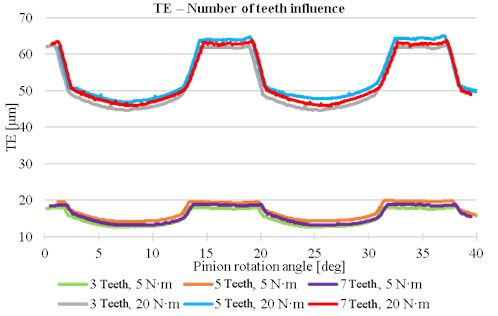
The next simplification to decrease the number of elements is the reduction of tooth number, which are used in the simulation. The number of teeth which are not in contact through analysis does not significantly affect the TE. The TE mean value has small difference, see Fig. 3. For next analysis only three teeth are used on each gear.
Fig. 2TE for different element size
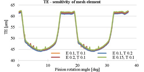
Fig. 3Influence of teeth number on the transmission error
3. Results
The TE of the same tooth profile is different based on the operation condition. With increasing torque, the mean value of TE is increased, see Fig. 4. To compare the best tooth profile, or the optimal operation condition for given gears the peak to peak value is used [7]. For calculated range 5-20 Nm the peak to peak value is increased.
The centre distance was increased from 67.5 to 67.7 to see the effect. The trend, that with increasing centre distance the TE value will increase, is confirmed for solved design, see Fig. 5.
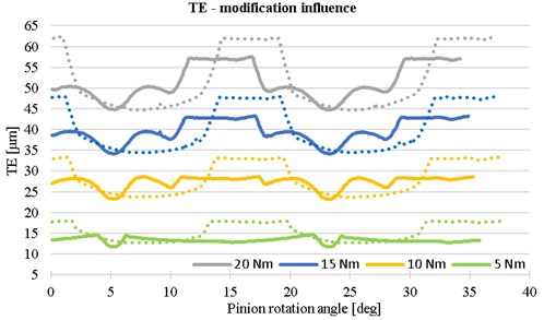
The goal of this analysis is to find the optimal tooth shape for torque in range 5-20 Nm. For that reason, the modifications of tooth were performed. The comparison of TE for gears with and without modification is shown on Fig. 6. The tooth with modification reaches lower value of TE for solved parameters.
Fig. 4The influence of torque on the transmission error
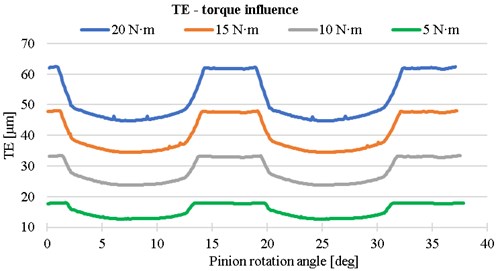
Fig. 5The influence of center distance on the transmission error
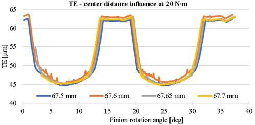
Fig. 6The influence of teeth modification on the transmission error
4. Conclusions
The spur gears were used for determination of static transmission error based on the numerical approach. The sensitivity study of computational time, size of elements in critical location and number of teeth in simplified geometry model was performed. The whole model was performed with regard to simple modification, thus the wide range of simulation can be performed without setting of analysis. Based on the results of transmission error it is possible to determine the best gears variant for given operation conditions. The identification of critical operation conditions is done based on the peak to peak value. This value is very sensitive to changes, but the different moment can be compared because the mean value is not taken into account.
The numerical approach will be used to calculate wide range of tooth number, tooth modification. The results will be used as input for MBS simulation as well as for direct comparison of static transmission error. The next step is validation of these result for both approaches on the simple modifiable single stage gearbox with possibility of gear change.
References
-
Sobiepanski M., Nieszporek T. Spur gears with longitudinal tooth profile modification mesh creating which is suitable for stress analysis. Technical Gazette, Vol. 24, Issue 6, 2017, p. 1657-1660.
-
Ghosh S. S., Chakraborty G. On optimal tooth profile modification for reduction of vibration and noise in spur gear pairs. Mechanism and Machine Theory, Vol. 105, 2016, p. 145-163.
-
Imrek H., Duzcukoglu H. Relation between wear and tooth width modification in spur gears. Wear, Vol. 262, 2007, p. 390-394.
-
Prokop A., Kopeckova B., Rehak K. Dynamic analysis of single stage gearbox focused on input parameters influence. Transport Means, Vol. 2017, 2017, p. 479-484.
-
Rehak K., Prokop A. Numerical simulation of single stage gearbox with tooth damage. Vibroengineering Procedia, 2016, p. 88-92.
-
Prokop A., Kopeckova B., Rehak K. Gear drive system simulation of input parameters effect on rattle. Acoustics and Vibration of Mechanical Structure, 2017, p. 381-388.
-
Kucera P., Pistek V., Prokop A., Rehak K. Transmission error analysis for heavy-duty gearbox. Vibroengineering Procedia, 2018, p. 113-116.
Cited by
About this article
This work is an output of the internal BUT research Project Reg. No. FSI-S-17-4104.

