Abstract
In this study, the fault diagnosis of nonlinear gearbox is investigated by using the frequency domain approach. The Nonlinear Output Frequency Response Functions (NOFRFs) of the nonlinear gearbox are evaluated and be used to diagnosis the abnormal conditions of the gears and the bearings. A case study is used to illustrate the NOFRFs based feature extraction method, then a probabilistic neural network (PNN) is mentioned to classify the failure modes. Finally, the results show that this method can complete the fault diagnosis of gearbox perfectly. The study provides a basis of the application of the NOFRFs and PNN in the fault diagnosis or condition monitoring of complex nonlinear systems.
1. Introduction
Gearbox plays an important part in modern industry and the its advantage makes it widely used in automobile, airplane, wind power system [1] etc. In general, the inside of the gearbox is made up of bearings, shafts and gears. Different from simple components, the failure and failure modes are various. Thus, the importance of fault diagnosis for gearbox is obviously.
In general, the frequency domain fault detection approaches are preferred in practice [2]. However, most of the frequency domain methods are conducted based on the linear theory, where the nonlinearities of the system are ignored or linearized.
Recently, a new concept known as the Nonlinear Output Frequency Response Functions (NOFRFs) has been proposed based on the Volterra series representation of a general class of nonlinear systems [3], which is expecting to solve these issues in the fault detection and fault diagnosis of nonlinear rotor-bearing systems. The NOFRFs is the natural extension of the Frequency Response Function (FRF) of linear systems, making it possible to analyze the nonlinear systems in the frequency domain in a similar way to linear systems. The NOFRFs based fault detection and fault diagnosis of nonlinear systems has also been widely studied, i.e. Cao et al. [4] combined the NOFRFs of the nonlinear system and the evidence theory for the fault detection and diagnosis of nonlinear complex systems. Peng et al. [5] used the NOFRFs to detect cracks in beams, showing that the NOFRFs are a sensitive indicator of the presence of cracks under an appropriate input excitation. In Zhao et al. [6], the nonlinear transmissibility derived by the NOFRFs were applied in the condition monitoring of structure damages.
In this study, the NOFRFs concept is applied in the feature extraction of nonlinear gearbox systems, and the results indicate that the higher order NOFRFs are more sensitive than the output frequency response to nonlinear faults which can be used to detect and quantify the nonlinear faults of the system. Then, the PNN is mentioned to classify the failure modes. These two methods work together to complete the fault diagnosis of the gearbox.
2. The NOFRFs based analysis of nonlinear systems
2.1. The frequency domain representation of nonlinear systems
In general, the nonlinear system that stable at zero equilibrium can be represented by using Volterra series as:
where and are the system output and input, respectively; is the th order Volterra kernel of the nonlinear system.
According to the Volterra series-based representation Eq. (1), in the frequency domain, the output spectrum of the system can be written as:
where is the output frequency and:
is the th order GFRF of the nonlinear system.
The GFRFs Eq. (3) of the nonlinear system can be evaluated by using the recursive algorithm. However, it can be seen that the GFRFs Eq. (3) is a multi-dimensional function which is difficult to compute and analysis, especially for higher order cases. To solve this problem, a new concept known as the NOFRFs of the nonlinear system was proposed [3], which is introduced as below.
2.2. The NOFRFs of nonlinear systems
The NOFRFs of the nonlinear system is defined as:
where is the th order output spectrum of the system, and:
Is the th input, such that the output spectrum Eq. (2) can be rewritten as:
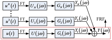
The new representation Eq. (6) indicate that the nonlinear system which can be represented by a Volterra series can be analyzed, similar to the FRF method of linear systems, by suing the NOFRFs. The approach is illustrated in Fig. 1.
It is worth noticing that, when the input of the nonlinear system is harmonic as:
where is the magnitude of the input signal, and are the input frequency and the phase, respectively, the NOFRFs based representation of the system can be written as:
where the NOFRFs under a harmonic input is independent to the input magnitude .
In practice, the NOFRFs of the nonlinear system can be estimated by using the LS, where the truncation order is assumed to be sufficient and a set of input with magnitudes are required. In this study, the NOFRFs under the harmonic input is applied for the feature extraction of the nonlinear gearbox system instead of the traditional frequency response detection method.
Fig. 1The NOFRFs based analysis of a nonlinear system

3. Fault classification based on PNN classifier
The PNN, first proposed by Dr. D. F. Speeht in 1989, is a branch of the radial basis Network, belonging to the feedforward Network. It has the following advantages: simple learning process, fast training speed; Classification is more accurate, fault tolerance and so on. In essence, it belongs to a supervised network classifier based on Bayesian minimum risk criteria.
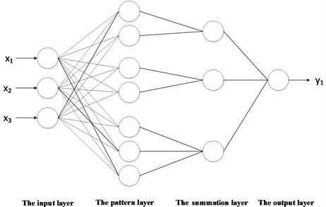
Fig. 2Basic structure of PNN

PNN generally have the following four layers: input layer, mode layer, summation layer, and output layer. In some materials, the pattern layer is also called the hidden layer, and the summation layer is called the competition layer. The input layer is responsible for transmitting the feature vector to the network, and the number of input layers is the number of sample features. The mode layer is connected to the input layer by a connection weight. Calculate the degree of matching between the input feature vector and each mode in the training set, that is, the similarity, and send the distance to the Gaussian function to obtain the output of the mode layer. The number of neurons in the pattern layer is the number of input sample vectors, that is, how many samples there are, and how many neurons there are. The summation layer is responsible for connecting the pattern layer units of each class. The number of neurons in this layer is the number of categories of samples. The output layer is responsible for outputting the highest score in the summation layer.
4. Case study
The data sets used in this paper come from the 2009 PHM Conference Data Analysis Competition.
Table 1Failure modes chosen of the samples
Case | Gear | Bearing | ||||||||
32T | 96T | 48T | 80T | IS: IS | ID: IS | OS: IS | IS: OS | ID: OS | OS: OS | |
1 | Intact | Intact | Intact | Intact | Intact | Intact | Intact | Intact | Intact | Intact |
2 | Chipped | Intact | Eccentric | Intact | Intact | Intact | Intact | Intact | Intact | Intact |
3 | Intact | Intact | Eccentric | Intact | Intact | Intact | Intact | Intact | Intact | Intact |
4 | Intact | Intact | Eccentric | Broken | Ball | Intact | Intact | Intact | Intact | Intact |
5 | Chipped | Intact | Eccentric | Broken | Inner | Ball | Outer | Intact | Intact | Intact |
6 | Intact | Intact | Intact | Broken | Inner | Ball | Outer | Intact | Intact | Intact |
4.1. Evaluation of the NOFRFs and Feature extraction of the vibration signals
The NOFRFs representation Eq. (6) of the system output spectrum under the new input can be rewritten as:
Such that the NOFRFs , , etc. can be evaluated by the followings.
Step 1: Test the system by using a set of different input signals , 1, …, with ;
Step 2: Compute the output spectrum of the system output under the test inputs, denote as , 1, …, ;
Step 3: Rewritten the NOFRFs representation into a matrix form as:
According to the tests results, where:
Step 4: Evaluate the NOFRFs by using the LS method as:
In this study, the truncation order of the NOFRFs representation is assumed to be 5, and five different inputs are applied to evaluated the NOFRFs.
4.2. Fault classification based on PNN classifier
After completing the work of NOFRF, the PNN model needs to be trained to classify the various patterns. First, the first 200 groups of each pattern were used as training data, and the last 100 groups were used as test data. Then the PNN classifier is obtained by using the training data. Finally, the trained PNN classifier is used to identify the test data and obtain the final fault diagnosis results. The results of the test data are shown in Table 2, indicating the excellent classification ability of PNN.
As is shown in Table 2, the method based on the NOFRFs and PNN has a good diagnostic result that the accuracies are not lower than 0.90 even when the gearbox under different cases.
Table 2Classification results based on the NOFRFs and PNN
Variety | Load | 30 Hz | 35 Hz | 40 Hz | 45 Hz | 50 Hz |
Input side data | High1 | 1.00 | 1.00 | 0.90 | 1.00 | 0.98 |
High2 | 1.00 | 1.00 | 1.00 | 1.00 | 1.00 | |
Low1 | 1.00 | 0.95 | 0.95 | 1.00 | 1.00 | |
Low2 | 1.00 | 1.00 | 1.00 | 0.97 | 1.00 | |
Output side data | High1 | 1.00 | 0.91 | 0.91 | 1.00 | 1.00 |
High2 | 1.00 | 1.00 | 1.00 | 1.00 | 1.00 | |
Low1 | 1.00 | 0.97 | 0.96 | 1.00 | 0.97 | |
Low2 | 1.00 | 0.99 | 1.00 | 1.00 | 1.00 |
5. Conclusions
The NOFRFs of nonlinear systems are the natural extension of the FRF for linear systems, which can be used for nonlinear systems analyses. In this study, the feature extraction of nonlinear gearbox system was completed by using NOFRFs concept, and then the fault mode was classified by using PNN classifier. The diagnostic results are obtained by study the vibration signals of gearbox. The results show that the way presented in this study can diagnose the gearbox failure perfectly.
References
-
Ewins D. J. Control of vibration and resonance in aero engines and rotating machinery – an overview. International Journal of Pressure Vessels and Piping, Vol. 87, Issue 9, 2010, p. 504-510.
-
Lei Y., Lin J., He Z., Zuo M. J. A review on empirical mode decomposition in fault diagnosis of rotating machinery. Mechanical Systems and Signal Processing, Vol. 35, Issue 1, 2013, p. 108-126.
-
Lang Z. Q., Billings S. A. Energy transfer properties of non-linear systems in the frequency domain. International Journal of Control, Vol. 78, Issue 5, 2005, p. 345-362.
-
Cao J., Chen L., Zhang J., Cao W. Fault diagnosis of complex system based on nonlinear frequency spectrum fusion. Measurement, Vol. 46, Issue 1, 2013, p. 125-131.
-
Peng Z. K., Lang Z. Q., Billings S. A. Crack detection using nonlinear output frequency response functions. Journal of Sound and Vibration, Vol. 301, Issue 3, 2007, p. 777-788.
-
Zhao X. Y., Lang Z. Q., Park G., Farrar C. R., Todd M. D., Mao Z., Worden K. A new transmissibility analysis method for detection and location of damage via nonlinear features in MDOF structural systems. IEEE/ASME Transactions on Mechatronics, Vol. 20, Issue 4, 2015, p. 1933-1947.
About this article
This research was supported by the National Natural Science Foundation of China (Grant Nos. 51605014, 51105019 and 51575021), the Aviation Science Fund (Grant No. 20163351018), the Technology Foundation Program of National Defense (Grant No. Z132013B002), and the Fundamental Research Funds for the Central Universities (Grant No. YWF-18-BJ-Y-159).
