Abstract
The paper describes some features of behavior of a mechanical system with self-synchronizing vibroexciters. The influence of friction torque in the bearings of vibroexciters rotors on their self-synchronization has been established by means of experimental research and mathematical simulation. Both the causes and frequency ranges of gaps in frequency responses has been found out. Further modification of the previously proposed algorithm for resonant tuning has expanded working regimes limits of the control system and improved resonant tuning stability.
1. Introduction
Power efficiency is one of the urgent problems in vibrating machines design which are widely used in modern mining technologies and material treatment [1-4]. By now, vibrating machines with unbalanced exciters operating in above-resonance mode have become widespread. This is due to the high stability of working body oscillations magnitude in relation to changes of machine parameters and operation load and relative simplicity and reliability of machine design. Main disadvantages of these machines are: low efficiency of driving force and the necessity of powerful motors to pass resonance [1, 3, 5].
One way to increase vibrating machines efficiency is to make them operate in resonant mode. However, usually resonant mode appears to be unstable because of nonlinearity of oscillating system, its interaction with the drive, technological load fluctuations, and etc. [5-8].
The issue of resonant mode stabilization is well developed for machines driven by DC motors [7-10]. In this case, the adjustment is performed by the system which controls motor angular velocity by regulating excitation current or supply voltage [8]. Papers [10, 11] consider different methods for resonant mode stabilization by controlling the angular velocity of rotating unbalanced exciters without specific reference to drive type.
For vibrating machines with AC motors, controlling the angular velocity of unbalanced exciters is a certain problem. This problem is associated with the slip effect which essentially depends on oscillations of machine working body [10, 12-14]. In [15, 16] the authors of this article proposed methods and algorithms for controlling resonant oscillations of single-mass vibrating machines with unbalanced exciter driven by AC motor. However, these works tended to consider excitation schemes with a single exciter. In case of several exciters, it is initially assumed that they rotate synchronously in opposite directions and produce unidirectional oscillations. Synchronization of exciters rotation is usually provided by the self-synchronization phenomenon [5, 17]. Note that self-synchronization occurs only under certain conditions which depend on parameters of oscillating system and parameters of oscillations (magnitude, frequency and mode shape). It is particularly difficult to maintain self-synchronization near resonance if system parameters and operation load change [15].
2. Design scheme of the machine
This paper considers dynamics features of a mechanical system with self-synchronizing exciters in the resonance zone on the example of a single-mass system. The oscillations of the system are excited by two unbalanced exciters driven by AC motors connected to a single power source. Design scheme of the considered system is shown in Fig. 1. The platform, simulating the working body of the machine, is considered as a rigid body on viscoelastic supports with linear elastic and damping characteristics. Cartesian coordinate system yOx is used to describe motion of the machine. Origin of the coordinate system is aligned with static equilibrium position of the platform’s center of mass.
Fig. 1Design scheme of the machine
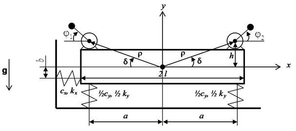
Two identical AC motors with equal unbalanced weights at both ends of the rotors are installed on the platform symmetrically with respect to the vertical axis Oy. The rotors’ axes are parallel with each other and perpendicular to the yOx plane. The motors are connected to three-phase AC power source via a single frequency converter so that their rotors rotate in opposite directions.
Motion of the system is described by five generalized coordinates: the linear displacements of the platform’s center of mass in the Ox and Oy directions, rotation angle φ of the platform and rotors’ rotation angles φ1 and φ2. All angular coordinates mentioned here are measured from the Ox axis counterclockwise. Differential equations of motion for the system have been derived using Lagrange equations of the second kind [19]:
where: mr1, mr2 – unbalanced masses of rotors, r1, r2 – eccentricities of unbalanced masses, Jr1, Jr2 – moments of inertia for unbalanced rotors; m=m0+mr1+mr2 – full mass of the system; m0 – mass of the platform; kx, ky, kφ – damping coefficients of supports in a horizontal, vertical and angular directions respectively; cx, cy, cφ – stiffness coefficients of the supports in horizontal, vertical, and angular directions, respectively; ρ1, ρ2 – distance from the platform’s center of mass to the axes of rotors respectively; δ1, δ2=π-δ1 – angles between the x axis and the axis, which pass through platform’s center of mass and the axis of the rotors in plane yOx (counted counterclockwise), and δ1=arctg(h/a), δ2=π-arctg(h/a), where h is distance between the axis of rotor and axis Ox;2a=2l is distance between springs, b= 0 (see Fig. 1); J=J0+mr1ρ21+mr2ρ22 – moment of inertia of the system; J0 – moment of inertia of the platform; g – gravitational acceleration; σ1=+1, σ2= –1 – constants that define the direction of rotors’ rotation; Mf1, Mf2 – resistance moment for the rotors.
Torques M1, M2 in right-hand side of Eq. (1) could be described by static characteristic of motors. The characteristics are obtained using simplified Kloss formula:
where Mcr1, Mcr2 – critical (maximum) torques for each motor, scr1, scr2 – slip at critical torque, s1=1-P|˙φ1/fe|, s2=1-P|˙φ2/fe| – current slip determined by frequency fe and angular velocities of the rotors ˙φ1, ˙φ2, P= 2 is a number of poles pairs.
The mathematical model provided, together with some results of the numerical simulation of its dynamics, taking into account the interaction with AC motors, were described in detail in [18].
In order to automatically adjust and maintain the resonance mode of oscillations, a frequency control system for the supply voltage has been developed and implemented [15, 16, 18]. An appropriate prototype in the form of resiliently supported platform with two motor-vibrators has been designed for experimental verification (see Fig. 2) [20].
Three main resonant frequencies have been defined experimentally: p1= 21 Hz, p2= 32 Hz; p3= 36.5 Hz. The frequency p1 corresponds to intense angular oscillation of the platform combined with horizontal oscillations with small magnitude. At the frequency p2 only vertical oscillations of the platform are excited. At frequency p3 intensive horizontal oscillations arise, combined with angular oscillations with relatively small magnitude. These experimentally defined resonant frequencies have been used to identify the parameters of the mathematical model.
However, the results of mathematical simulation and experiments have revealed a number of particular properties that were not described before.
This mainly relates to the influence of friction torque in the bearings of motors rotors on the self-synchronization of the exciters, and also to instability of the oscillations on frequencies above vertical resonant frequency. These recently revealed properties required certain modifications of the previously proposed control algorithms.
3. Influence of friction torque in the bearings of exciters
Experimentally, we found that near the vertical resonance, when the exciters rotate in opposite directions with equal velocities, the difference in their phase angles could be observed. This indicates that the required condition of self-synchronization is violated at the antiphase rotation of the exciters.
Fig. 2 shows the position of the exciters, at a fixed moment of time, in stroboscopic illumination at synchronous frequency of 29 Hz (the resonant frequency is 32 Hz). The strobe frequency is synchronized with the lowest position of the right-hand disbalance. It can be seen, that the left-hand disbalance is rotated at an angle α≈ 15° relatively to the right-hand disbalance position. Work [17] mentioned the influence of different friction torques on the self-synchronization.
Braking torque Mf has been applied to each rotor successively to estimate the influence of friction experimentally.
Fig. 3 shows a relative position of the debalances, when the braking torque is applied to the left rotor. Increase in braking moment leads to decrease in the mutual phase angle α down to zero.
If the braking torque is applied to the right rotor, the mutual phase angle α increases (see Fig. 4).
So, the difference in the phase angles of disbalances can be explained by a higher friction torque in the right-hand engine compared to the left-hand one.
Numerical analysis of the influence of friction has been carried out based on mathematical model described in [18].
Fig. 2Relative position of the debalances
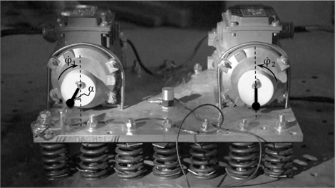
Fig. 3Relative position of the debalances: additional friction torque applied to the left-hand rotor
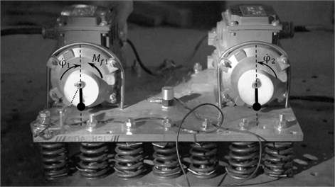
Fig. 4Relative position of the debalances: additional friction torque applied to the right-hand rotor
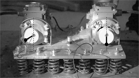
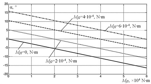
Fig. 5 shows results of calculation of the mutual phase shift between the disbalances as a function of friction torque at the same frequency of 29 Hz, as in the experiment. Zero phase difference corresponds to the synchronized rotation of debalances when the platform oscillates in vertical direction only. This synchronized rotation mode could be achieved only when friction torques in the supports of the rotors are equal. Any difference in these friction torques leads to a non-synchronous mode of rotation, so the unidirectional excitation mode appears to be disrupted. At the same time, the greater is the difference in frictional torques, the greater is the difference in phases of debalances.
Note that the described phenomenon of phase angles difference of self-synchronized exciters can be used in motors diagnostics.
Fig. 5Influence of the friction torque on the difference in phase angles of disbalances
4. Analysis of dynamics features
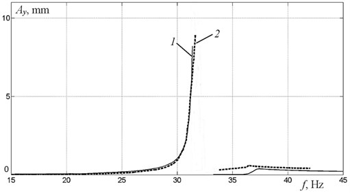
Detailed analysis of the experimental and theoretical frequency response obtained in [19, 20] showed that oscillations at above-resonant frequencies of vertical oscillations are represented by unstable chaotic motions. This instability can be seen in frequency response characteristic as a jump (see Fig. 6, where the solid line (curve 1) represents numerical simulation result, and the dotted line (curve 2) represents the experimental results). Starting from about 34 Hz, stable oscillations regain in the system with a new type of synchronization of exciters, which is characterized by a relative phase shift α= 180°. At the same time, the vertical component of the exciting force disappears and there are scarcely any vertical oscillations of the platform’s center of mass (note that the vertical movement of the platform both in numerical simulation and in experiment is determined by the position of the center of mass). As a result, the phase shift ε between the vertical oscillations of the platform and the exciting force in the range from the second resonant frequency to the third resonant frequency can’t be determined, as it is seen from the phase calculation results (see Fig. 7). In the frequency range above the third resonant frequency, another type of synchronization with relative phase shift α= 0° between disbalances occurs. It again leads to the appearance of vertical oscillations with phase shift ε= 180°. Note that, when approaching to the second resonant frequency, the phase shift increases monotonically, but the value of 90° can’t be reached because of the abrupt jump into the above-resonant region. This jump is caused by nonlinearity of the interaction between the oscillating system and the exciter of limited power.
Fig. 6Frequency response for vertical oscillations
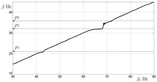
Described dynamics features near the resonance are also related to slip in AC motors. Fig. 8 demonstrates experimentally obtained debalance rotation frequency dependence on the motors power supply frequency. In non-resonance regions this dependence is linear. But when approaching to resonances, increase in power supply frequency leads to no change in motor speed. This is due to slip effect in the AC motors and their limited power. Further increase in power supply frequency leads to significant change in motor rotation speed. This is mostly evident in the region of the second resonant frequency which corresponds to vertical oscillations mode. The range of nonlinear motors rotation speed dependence on power supply frequency correlates with the instability zone observed at the frequency response and phase shift plots.
Fig. 7Phase shift between vertical oscillations and vertical exciting force
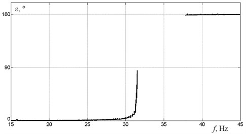
Fig. 8Rotors rotation speed as a function of power supply frequency
5. Control system
The previously proposed in [15] control algorithm for automatic tuning and resonant mode maintaining takes into account possible changes in the mass of the system, which leads to a change in the resonant frequency. Phase shift ε between vertical oscillations of the platform and vertical component of disturbing force, determined in steady state, is taken as the main controlled parameter that determines the oscillation mode of the whole system. The criterion for resonant mode achieving is the value of the phase shift ε= 90°.
To determine the change in power supply frequency, required to adjust the system to resonant mode, dynamic portrait conception has been developed [15]. Dynamic portrait is relationship between three system parameters: phase shift, power supply frequency, and natural frequency of the system (or mass, if we consider it as a changing parameter of the system). Dynamic portrait can be represented graphically as a three-dimensional surface. Dynamic portrait for a particular machine supposed to be derived from the solutions of corresponding system Eq. (1). Thus, the shape of the surface depends on the parameters of the machine, while each point of the surface represents the dynamic state of the machine with parameters corresponding to the coordinates of the point.
Power supply frequency required to adjust the system to resonant mode could be determined using dynamic portrait in two steps. In the first step the unknown natural frequency of the system is determined. In the second step, power supply frequency corresponding to resonant mode is determined, using the value found in the first step.
The revealed features of the system dynamics in the resonance region require following changes in the control algorithm. First of all, it is necessary to take into account that abrupt jump into the above-resonant region occurs before the phase shift value ε reaches 90°. Preliminary calculations showed that this abrupt jump usually occurs in the range ε*= [81°, 87°] depending on the parameters of the system. So, the control algorithm needs using the indicated range of ε* as a criterion for resonant mode, instead of ε= 90°. Moreover, the algorithm must take into account the uncertainty of the phase shift ε after abrupt jump into above-resonant region that leads to the gap in the dynamic portrait. In real conditions, this uncertainty does not let to measure system parameters using dynamic portrait.
In the case when abrupt jump into above-resonant region occurs due to tuning to a new resonant mode or after the system mass changes, it is necessary to return to the previous known stable below-resonance mode and continue tuning from this state. Thus, the modified algorithm works in the following way.
The control cycle begins with measurement of oscillations and angular positions of debalances, which are used to compute current value of phase shift ε. Then it is checked if oscillations of the system are stable. Oscillations supposed to be unstable if variance of phase shift values Δε on selected time interval exceeds some predetermined value (1° for instance). In this case, a period of staying in unstable mode is checked. If this period exceeds some selected threshold value, the system returns to the previous below-resonant state. This state is defined by the minimum allowable resonant frequency of vertical oscillations, which is determined by the known maximum permissible mass of the entire system. If a stable oscillating mode is detected, current value of phase shift is checked, which indicates if the machine is in above-resonant mode or in below-resonant mode. If the machine appears to be in the above-resonant mode, it sets to the below-resonant mode. In the below-resonant mode tuning criterion is checked for the near-resonant mode (ε*= [81°, 87°]). If this resonant criterion is satisfied, the control cycle continues to be executed to track possible changes. Otherwise, new power supply frequency value is computed using dynamic portrait of the system. After that, the computed power supply frequency value is set using a controlled frequency converter.
6. Simulation results
To test the efficiency of the proposed control system, numerical simulation has been carried out, supposing mass of the system varies according to the piecewise law shown in Fig. 9. The simulation was carried out with parameters of the model given in [18, 20].
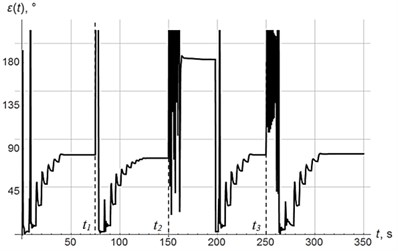
Fig. 10-12 show diagrams of vertical oscillations of the platform, power supply frequency and phase shift. At time t= 0, the system starts to oscillate with power supply frequency of 55 Hz in below-resonant mode. Control system tunes the oscillating system into the resonant mode in 6 regulation steps. In this case, the phase shift reaches ε= 83°. At time t=t1, mass of oscillating system decreases abruptly (see Fig. 9), which leads to increase in resonant frequency, so the system appears in below-resonant mode again. Control system performs resonant tuning in 7 regulating steps, phase shift reaches ε= 81°. At time t=t2, mass of oscillating system increases significantly, which leads to decrease in resonant frequency, so the system appears in above-resonant mode. This transition is accompanied by chaotic changes in phase shift (Fig. 12). In accordance with the modified algorithm, at first oscillating system is re-tuned to below-resonant mode with power supply frequency of 55 Hz, and then resonant tuning is performed in 6 steps with a phase shift ε= 83°. At time t=t3, mass of oscillating system increases abruptly again so the system appears in above-resonant mode again. Resonant tuning is performed in the same way as on the previous stage.
Thus, regardless of mass changes (increase or decrease), resonant tuning is performed in 6-7 regulation steps. Note that relatively high delay between regulation steps is caused by slow decay of the transient processes due to small dissipation in the system.
Fig. 9Changes of mass of the system
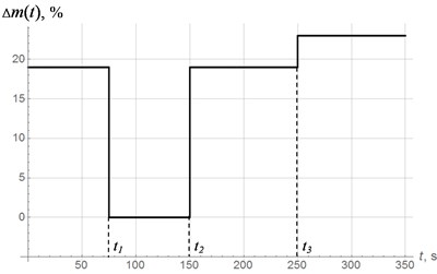
Fig. 10Vertical oscillations of the center of mass
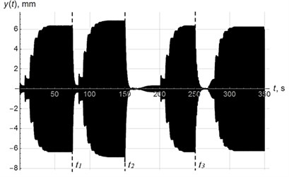
Fig. 11Supply frequency fet
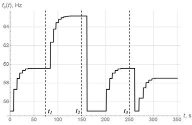
Fig. 12Phase shift εt
7. Conclusions
Thus, as a result of theoretical and experimental analysis of dynamics of oscillating system with self-synchronizing unbalanced exciters, we have established the influence of friction torques in supports of the exciters on their self-synchronization.
There has been found a frequency range where a phase shift between vertical oscillations and vertical component of exciting force cannot be determined. The problem is caused by absence of vertical oscillations of system’s center of mass, due to abrupt jump into the above-resonant region and changes in the type of synchronization.
It has been found that near the second resonance, an abrupt jump of oscillation occurs at phase shift value less than 90° due to nonlinear interaction between the vibrational system and limited power exciters. The value of the phase shift when the abrupt jump occurs depends on parameters of oscillatory system.
Such behavior of the system results in a gap in frequency response characteristic, which makes it impossible to use the phase shift as a controlled parameter in the control system in this frequency range.
Taking into account these newly discovered phenomena, a modification of the algorithm for resonant tuning has been carried out. The modification consists in transferring the system from the unstable above-resonant mode to the certain stable below-resonant mode.
This research allows to expand the control system operating range, as well as to increase resonant tuning stability.
References
-
Vaisberg L. A. Design and Calculation of Vibrating Screens. Nedra, Moscow, 1986, (in Russian).
-
Astashev V. K., Kolovsky M. Z., Babitsky V. I. Dynamics and Control of Machines. Springer-Verlag, Berlin Heidelberg, 2000.
-
Lavendelis E. E. Vibration in the Technique: Handbook, Vol. 4. Vibration Processes and Machines. Mechanical Engineering, Moscow, 1981, (in Russian).
-
Wu A., Sun Y. Granular Dynamic Theory and Its Applications. Springer-Verlag, Berlin Heidelberg, 2008.
-
Blekhman I. I. Vibrational Mechanics. Nonlinear Dynamic Effects, General Approach, Applications. World Scientific Publishing Co., Singapore, 2000.
-
Wagg D., Neild S. Nonlinear Vibration with Control: For Flexible and Adaptive Structures. Springer International Publishing, Vol. 218, 2015.
-
Balthazar J. M., Cheshankov B. I., Ruschev D. T., Barbanti L., Weber H. I. Remarks on passage through resonance of a vibrating system with two degrees of freedom, excited by a non-ideal energy source. Journal of Sound and Vibration, Vol. 239, Issue 5, 2001, p. 1075-1085.
-
Astashev V., Babitsky V., Sokolov I. Autoresonant vibration excitation by synchronous motor. Journal of Machinery Manufacture and Reliability, Vol. 4, 1990, p. 41-46.
-
Shiriaev A. S., Fradkov A. L. Stabilization of invariant sets for nonlinear systems with applications to control of oscillations. International Journal of Robust and Nonlinear Control, Vol. 11, 2001, p. 215-240.
-
Skubov D., Khodzhaev K. S. Non-Linear Electromechanics. Springer-Verlag, Berlin Heidelberg, 2008.
-
Felix J. L. P., Balthazar J. M., Brasil R. M. L. R. F. On Saturation control of a non-ideal vibrating portal frame foundation type shear-building. Journal of Vibration and Control, Vol. 11, 2005, p. 121-136.
-
Maaziz M. K., Boucher P., Dumur D. A new control strategy for induction motor based on nonlinear predictive control and feedback linearization. International Journal of Adaptive Control and Signal Processing, Vol. 14, 2000, p. 313-329.
-
Boukas T. K., Habetler T. G. High-performance induction motor speed control using exact feedback linearization with state and state derivative feedback. IEEE Transactions on Power Electronics, Vol. 19, 2004, p. 1022-1028.
-
Holopainen T. P., Tenhunen A., Arkkio A. Electromechanical interaction in rotor dynamics of cage induction motors. Journal of Sound and Vibration, Vol. 284, Issues 3-5, 2005, p. 733-755.
-
Panovko G., Shokhin A., Eremeykin S. The control of the resonant mode of a vibrating machine that is driven by an asynchronous electro motor. Journal of Machinery Manufacture and Reliability, Vol. 44, Issue 2, 2015, p. 109-113.
-
Panovko G., Shokhin A., Eremeykin S., Gorbunov A. Comparative analysis of two control algorithms of resonant oscillations of the vibration machine driven by an asynchronous AC motor. Journal of Vibroengineering, Vol. 17, Issue 4, 2015, p. 1903-1911.
-
Blekhman I. Synchronization of Dynamic Systems. Nauka, Moscow, 1971, (in Russian).
-
Eremeykin S. A., Panovko G. Y., Shokhin A. E. On the problem of control resonance oscillations of a mechanical system with unbalanced. Proceedings of the 9th European Nonlinear Dynamics Conference, Budapest, Hungary, 2017.
-
Panovko G., Shokhin A., Eremeykin S. Experimental analysis of the oscillations of a mechanical system with self-synchronized inertial vibration exciters. Journal of Machinery Manufacture and Reliability, Vol. 44, Issue 6, 2015, p. 492-496.
-
Panovko G., Shokhin A., Eremeykin S. Adaptive properties of a self‑synchronization effect of unbalanced vibroexciters. Vibroengineering Procedia, Vol. 6, 2015, p. 321-325.
Cited by
About this article
The research was supported by the Russian Science Foundation, Project No. 15-19-30026.
