Abstract
Mechanical vibration is the main noise source of underwater vehicle. The foundation of the main power is an important pathway of mechanical noise. Large size foundation of the power not only affects the vibration transmitted from the power to the hull structure, but also affects the vehicle shell radiation area and radiation efficiency, thus affecting the radiation noise of underwater vehicle. Based on the study of the influence of the large size foundation arrangement on the radiated noise of underwater vehicles, two new types of foundation arrangement were proposed. The foundation could meet the requirements on the acoustic performance, and could greatly reduce the radiation surface area of the shell and reduce the radiated Sound Pressure. To the power compartment general layout and support function, three foundation layout schemes such as continuous style, large span style and bulkhead support style in the typical excitation of power equipment were designed. Further way, far field underwater radiation noise of the compartment was numerically calculated. The results show that bulkhead support style can effectively reduce underwater acoustic radiation of the compartment shell on the premise of the meet the weight control and impedance characteristics.
1. Introduction
The noise control of underwater vehicle is of vital importance on the defence technology as well as underwater ecosystem, for evidence has been steadily accumulated of adverse fish reactions to some vessels. Accordingly, there are abundant works having been done by proceeding researchers.
Ross D [1] has elucidated the basic mechanisms by which noise of the surface ship as well as the underwater vehicle is generated, transmitted by structures and radiated into the sea. Mitson R. B. [2] has examined the factors pertaining to underwater radiated noise from vessels used to conduct fisheries research, and this work shows the significant detriment of underwater noise to fish and threw a light on how to alleviate such kind of bad effect. Winberg Mathias, et al. [3] studied on the problem associated with low order harmonics generated by the main diesel engines, transmitted through the engine mounts into the hull, and subsequently radiating into the water, coming up with the conclusion that active vibration control of the intermediate mass of the existing diesel engine mounts is a practical way of reducing the 1.0, 1.5 and 2.0 engine order components in the noise spectrum radiated as a result of vibration transmission through the engine mounts.
To design and control the vibration and noise of underwater vehicles, it is an indispensable task to acquire a reasonable technique to simulate the originating and transmitting of the vibration and sound properly. Lots of attempts has been taken to cope with such a problem.
Among various underwater acoustic simulation techniques, the finite element method (FEM) stand out for its accuracy and effectiveness. Zheng H. and Liu G. R. [4] made a numerical prediction of vibration transmission from a ship diesel via a resilient mounting system to a stiffened cylindrical hull is performed aiming to provide a clearer insight into the significance of piston-slap in the diesel excitation to the hull vibration, and consequently, the underwater radiated noise with FEM. Zhang Qifan and Wei Li [5] set up an integrated approach of acoustic radiation analysis, useful to assess and optimize vibro-acoustic performance to pre-determined design targets, while identifying and quantifying the sound sources responsible for the current behaviour with acoustic transfer vector (ATV) technology. Chai Y. and W. Li [6-9] had developed a smooth finite element method (SFEM) applying to cope with underwater acoustic problems accurately and effectively.
In this paper, the far field underwater radiation noise of an underwater vehicle layout with three different foundation, such as continuous style, large span style and bulkhead support style, were simulated with FEM though Virtual-Lab. Further, by comparing the result of these three schemes, the noise and vibration control ability of each type of foundation layout scheme were discussed.
2. FEM on structural-acoustic problems
The finite element method (FEM) is a numerical method extensively applied in engineering and mathematical physics. This method has been proved to be effective and accurate in dealing with problems on structural analysis, acoustics, heat transfer, fluid flow, mass transport, and electromagnetic potential as well as the coupling problems combined with two or more fields referred formerly. The problem mentioned above could be modelled as boundary value problems of partial differential equations. The unknown continuous parameters, such as displacement, Sound Pressure, temperature, and so on, could be approximated as several values of the unknowns at discrete point over the domain the problem concerns. Then, the problem can be divided into smaller, simpler parts that are called as finite element, which could be shaped as triangle, square, cube, triangular pyramid, and so on. Subsequently, the discrete equation can be assembled into a large system of equations that model the entire problem. With boundary specified conditions, this FE matrix modelling the entire problem could be solve with numeric algorithm.
For a structural problem, the solid structure could be modelled with a discrete finite element matrix equation as:
where, represents the structural stiffness matrix, and is the structural mass matrix. is the displacement at each node, and the is structural boundary condition.
For an acoustic problem, the discrete FEM matrix equation could be presented as:
where, , and stand, respectively, for the fluid inertial matrix, the fluid compressibility matrix and fluid damping matrix. contains the Sound Pressure, and is the acoustic source term due to velocity boundary conditions acoustic sources in the fluid domain.
On the interface between the structural domain and the acoustic domain, there exist coupling effects between these two field. Accordingly, the FEM matrix equation in this area should be represented as:
where, matrix represents the coupling effect between the structure and acoustic fluid, which satisfies:
where, is the coupling surface between structure and fluid, and n is the normal vector.
In this work, the coupling elements was defined via an automatic algorithm through LMS Virtual Lab: for a normal line in each integration node of the structural elements, the closest acoustic elements within a certain tolerance are regarded as coupling elements. Subsequently, the FEM matrix of the whole system could be assembled.
3. Description of the problem
To make clear the relationship between the layout schemes and the radiation noise of the hull, a compartment of an underwater vehicle was set as an example to calculate its characteristics about vibration and noise. As is shown in Fig. 1, the prototype compartment, whose length is 9.6 m, is consisted of a structure of double shells, an inner shell whose radius is 3.5 m and an outer shell whose radius is 4.5 m, as well as a heavy platform weighted about 50 t mounted on a brace fixed to the inner shell with 10 vibration isolators. The information fore-mentioned is the structural part of the problem. Moreover, there is sufficient fluid wrapped the structure up, and the fluid is divided into two parts, one part is out of the outer shell and the other part is in vicinity of the inner shell and the outer shell, because the outer shell is not completely sealed as is shown in Fig. 2.
Then, the Mean Square Velocity on the inner shell surface, Sound Pressure at field point and Radiation Power were calculated of different compartment models originated from the proto type by modifying the foundation layout scheme. The following sections will introduce the information about the different foundation layout schemes, the excitation point and the key points observing the physical characteristics fore-mentioned sequentially.
Table 1Structural parameters
Young’s modulus | 200 GPa |
Poisson’s ratio | 0.3 |
Density | 7800 kg/m3 |
Table 2Fluid parameters
Density | 1025 kg/m3 |
Sound speed | 1500 m/s |
Reference pressure | 1.0×10⁻⁶ N/m2 |
3.1. Foundation layout schemes
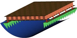
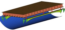
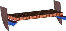
As is shown in Fig. 1, three different foundation layout schemes were considered.
Fig. 1Three different foundation layout schemes excitation point arrangement
a)
b)
c)
In Fig. 1(a), the platform was connected to two surface plates with 10 vibration isolators on left-and-right sides of the foundation, and the two surface plates were welded to two sequences of ribs fixed to the bottom of the inner shell, and this layout scheme is called as continuous style, also called as prototype.
Then, in Fig. 1(b), it depicts the second scheme, large span style, whose most ribs connecting the inner shell and surface plate were removed in contrast with Scheme 1, and replaced with a longitudinal T-bar, which was not fixed to the inner shell.
In Fig. 1(c), it shows bulkhead support style, which is quite different from the prototype, whose surface plates were no longer arranged in longitudinal direction but transverse, and were welded to the front-and-back bulkheads with ribs arranged transversely, and the connection between the platform and the surface plates were adjusted onto the front-and-back sides accordingly.
3.2. The arrangement of key characteristics
3.2.1. Mean square velocity
After the structural-acoustic simulation of each scheme, the vibrating velocity varying along with the frequency spectrum of each structural node will be calculated. To assess the magnitude of the vibration of the structure of each scheme, there will be an algorithm adding the square velocity of every structural nodes on the inner shell, and getting the mean. The mean value varied on different frequency will be defined as Mean Square Velocity curve.
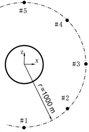
Fig. 2Sound pressure points
3.2.2. Sound pressure
The Sound Pressure of the simulation of each scheme was calculated. To tell the properties of Sound Pressure of each model, 5 field points were picked, arranged as Fig. 2, 45° spaced between any two adjacent points, and at a distance of 1000 m with the structure. And all points scattered on the middle section of the compartment.
3.2.3. Radiation power
While vibrating, the structure would emit sound to all directions, and the collective power around the structure is Radiation Power. In Virtual Lab, a sphere is used to enclose the structure, and the radiation acoustical power detected on the sphere will be integrated into Radiation Power, a character to describe the energy emitted by the vibrating structure.
4. Result and analysis
As is discussed above, the Mean Square Velocity on the inner shell, Sound Pressure at the five field points, and the Radiation Power on the far field sphere could be extracted from the simulation result, and these characters will be presented subsequently to assess the vibration and radiation noise property of each scheme.
4.1. Result of mean square velocity on the inner shell
The velocity of every nodes on inner shell was taken into account to calculate the Mean Square Velocity of the inner shell, and the 1/3OCT curve of the Mean Square Velocity Level (MSVL), in which the reference velocity was set as 10-9 m/s, could be depicted as Fig. 3.
Fig. 31/3OCTcurve of mean square velocity on inner shell
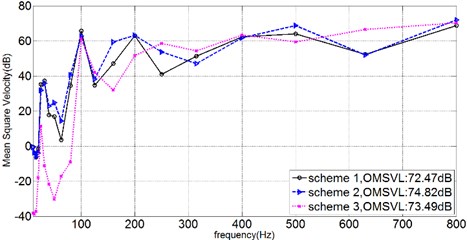
In general, it could be told from Fig. 3 that the Overall Mean Square Velocity Level (OMSVL) value of Scheme 2 is strongest, and the OMSVL value of Scheme 3 is weaker, and the OMSVL value of Scheme 1 is weakest. When just focusing on the MSVL at the frequency band between 0 Hz-200 Hz, it can be informed that the OMSVL of Scheme 3 is weakest at this frequency band. And the OMSVL of these three schemes shows a similarity at the frequency band between 300 Hz-500 Hz. However, the OMSVL value of Scheme 3 is much bigger than the others at some specific frequency point such as 250 Hz and 630 Hz.
4.2. Sound pressure result
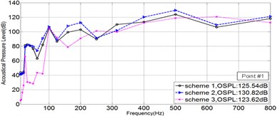
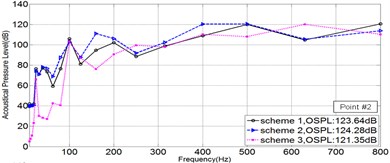
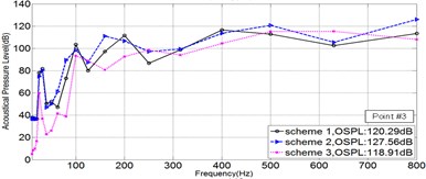
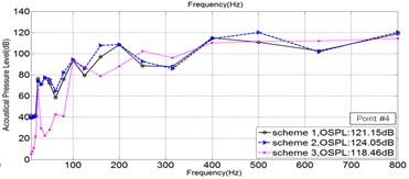
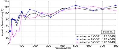
As is shown in Fig. 2, five points in Sound Pressure field were picked, to illustrate the Sound Pressure property of each scheme. The Sound Pressure Level (SPL) at five field points of each scheme was extracted and illuminated in Fig. 4 via 1/3OCT SPL curves.
Fig. 41/3OCTcurve of sound pressure level at 5 field points
a)
b)
c)
d)
e)
As is illuminated in Fig. 4, at Point 1 to Point 4, the OSPL value of each scheme in a sequence: Scheme 3 < Scheme 1 < Scheme 2, and the OSPL value of Scheme 3 is slightly bigger than Scheme 2 and greatly less than Scheme 2. Accordingly, it could be safely concluded that Scheme 3 is the most effective way to control noise, however Scheme 2 leads adverse effect in controlling noise. Moreover, by comparing the SPL curve at every Point, it could be told that the noise controlling effect of Scheme 3 is much more obvious when the frequency is less than 200 Hz.
5. Conclusions
In this paper, a model of an underwater vehicle compartment model was discussed. By simulating the vibration and sound properties of different models of three different foundation schemes, the Mean Square Velocity, Sound Pressure, and Radiation Power has been extracted to analysis the noise control effect of different schemes. And the conclusions followed as below:
1) Scheme 3 is an effective way to control noise because the OSPL and ORPL of Scheme 3 is much smaller than Scheme 1, although the OMSVL of Scheme 3 is slight stronger than Scheme 1.
2) Scheme 2 is not a good approach that should be applied in controlling noise of the model discussed in this paper, for the three characteristics, OSPL, ORPL, and OMSVL, are much bigger than the prototype.
2) The noise control effect of Scheme 3 is more distinct at low frequency band which is lower than 200 Hz.
References
-
Ross D. Mechanics of Underwater Noise. Elsevier, 2013.
-
Mitson R. B. Underwater Noise of Research Vessels. ICES Cooperative Research Report 61, 1995.
-
Winberg Mathias, et al. Active Control of Engine Vibrations in a Collins Class Submarine. Blekinge Institute of Technology, Department of Telecommunications and Signal Processing, 2003.
-
Zheng H., Liu G. R., Tao J. S., Lam K. Y. FEM/BEM analysis of diesel piston-slap induced ship hull vibration and underwater noise. Applied Acoustics, Vol. 62, Issue 4, 2001, p. 341-358.
-
Qifan Zhang, Li W., Wang Chizhong The Fast Prediction of Sound Radiation from Typical Submarine Cabin Based on Acoustic Transfer Vector. Ocean Acoustics, China, 2016.
-
Li W., Chai Y., Qifan Zhang Vibration and Radiation from Underwater Structure in Shallow Water. OCEANS, Shanghai, 2016.
-
Chai Y., Li W., Gong Z., Li T. Hybrid smoothed finite element method for two-dimensional underwater acoustic scattering problems. Ocean Engineering, Vol. 116, 2016, p. 129-141.
-
Chai Y., Li W., Li T., Gong Z., You X. Analysis of underwater acoustic scattering problems using stable node-based smoothed finite element method. Engineering Analysis with Boundary Elements, Vol. 72, 2016, p. 27-41.
-
Chai Y., Li W. Hybrid smoothed finite element method for two-dimensional acoustic radiation problems. Applied Acoustics, Vol. 103, 2016, p. 90-101.
-
Gong Z., Chai Y., Li W. Coupled analysis of structural-acoustic problems using the cell-based smoothed three-node mindlin plate element. International Journal of Computational Methods, Vol. 13, Issue 2, 2016, p. 1640007.
