Abstract
As common structure of underwater vehicle, the accurate prediction of underwater vibration and acoustic radiation of double cylindrical shell is always a difficult problem in the research of vibration and noise. Establish finite element model of double cylindrical shell in Abaqus software. Based on the three-dimensional sono-elasticity theory of ships, analysis vibration and acoustic radiation characteristics of underwater double cylindrical shell by the use of Thafts-acoustic software, and compared with experimental result. Results show that error of prediction result and experiment result at single frequency point is about 10 %~20 %, and error of total level of acceleration and sound pressure is less than 5 dB. It is accurate to predict the underwater vibration and acoustic radiation characteristics of double cylindrical shell with three-dimensional sono-elasticity theory of ships, which can provide new effective guidance for the engineering application.
1. Introduction
Double cylindrical shell is one of the common structure of underwater vehicle. With the further improved requirement of modern war on acoustic stealth performance of underwater vehicle, the study of vibration and sound radiation prediction technology of underwater double cylindrical shell is becoming increasingly important. To this end, domestic and foreign scholars have carried out a lot of research work. From the shell vibration control equation, literature [1] derived finite or infinite cylindrical shell’s vibration and acoustic radiation analytic expression using modal expansion method; literature [2] derived vibration and acoustic radiation approximate analytical solution of finite stiffened cylindrical shell; literature [3] studied the acoustic radiation response of submerged finite cylindrical shell by the use of analytical and numerical methods; literature [4] established acoustic coupling equation of finite ring and longitudinal ribs stiffened shell by Flügge vibration theory, derived vibration and acoustic radiation analytical expression of stiffened shell under single-frequency multi-source excitation; literature [5] established the vibration and acoustic transfer path analysis (TPA) model of underwater structure, to effectively identify, quantify the main noise source and noise transmission path; literature [6] analysed the vibration and acoustic transfer path of double cylindrical shell under fluid - solid coupling condition by finite element method.
For double cylindrical shell with complex structure, analytical solution for solving vibration and acoustic radiation is almost impossible. In this article, three-dimensional sono-elasticity theory of ships is applied to analysis underwater vibro-acoustic characteristics of double cylindrical shell, predict the underwater vibro-acoustic characteristics with the help of software Thafts-acoustic by using numerical method and validate the accuracy of the prediction result by comparing with experimental result.
2. Model introduction
Double cylindrical shell is composed of outer shell, inner shell, ring ribs, end covers and elastic panel. Inner and outer cylindrical shell is connected via ring ribs and ring ribs are uniform along the cylindrical shell. Elastic panel locates in cylindrical shell’s horizontal middle position. The upper and lower side of the outer cylindrical shell is slotted, the water can fill the cavity between the inner and outer cylindrical shell when cylindrical shell is underwater. Model Parameters are shown in Table 1.
Establish half dry model and finite element model of double cylindrical shell using Abaqus software, which are shown in Fig. 1.
Table 1Model parameters
Parameter | Value | Parameter | Value |
Shell length / m | 2.0 | Outer shell radius / m | 0.6 |
Ring rib spacing / m | 0.4 | Inner shell radius / m | 0.5 |
Outer shell thickness / m | 0.004 | Material density / kg·m-3 | 7.8e+03 |
Inner shell thickness / m | 0.008 | Elastic modulus / n·m-2 | 2.1e+11 |
Elastic panel thickness / m | 0.008 | Poisson’s ratio | 0.3 |
End cover thickness / m | 0.012 |
Fig. 1Cylindrical shell model
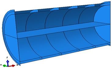
a) Geometry model
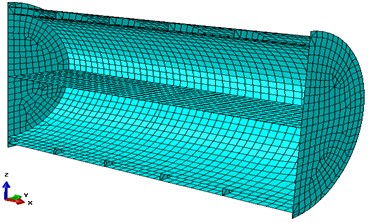
b) FEM model
3. Three-dimensional sono-elasticity calculation method of ships with double basin coupling
The schematic diagram of the acoustic elastic coupling decomposition of inner and outer flow field is shown in Fig. 2.
Fig. 2Schematic diagram of acoustic elastic coupling decomposition calculation of the inner and outer flow field
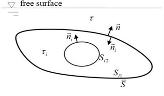
a) Coupling calculation model of outer flow field and shell
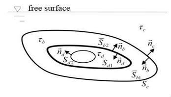
b) Coupling calculation model of inner flow field and shell
Inner and outer flow field are not mutually connected aqueous medium. The inner and outer flow fields are regarded as two independent flow fields, and the attached water mass, attached water damping and generalized recovery coefficient caused by inner and outer flow field were calculated respectively. Fig. 2(a) shows the outer flow field and shell coupling mathematical model, where is the ideal sound medium outflow field, is outer flow field corresponding average wet surface, on which the unit normal vector is ; is imaginary inner flow field encircled by the wet surface which is coincident with and virtual impedance surface . Fig. 2(b) shows the inner flow field and shell coupling mathematical model, where is inner flow field, corresponding to the average wet surface and ; is imaginary outer flow field, corresponding to wet surface which is coincident with . Since the virtual outer flow field is semi-infinite flow field and there is no resonance problem, so there is no need to introduce a virtual impedance surface; is imaginary inner flow field encircled by , wet surface and a virtual impedance surface .
3.1. Coupling effect of flow field and shell
By the modal superposition method, nodal displacement of the double cylindrical shell structure discrete systems can be expressed as:
where is the modal displacement column vector corresponding to -order modal, and are respectively generalized primary coordinate column vector principal coordinate and -order dry modal primary coordinate components.
Generalized kinetic equation for double cylindrical shell vibration can be expressed as:
where [], [], [] were dry structure modal generalized mass matrix, generalized damping matrix and generalized stiffness matrix; , were generalized force column vector corresponding to outer excitation force in non-voice media flow field and generalized hydrodynamic column vector corresponding to acoustic medium flow field force on wet surfaces.
First, consider the outer flow field and shell coupling at zero speed. By adding the inner and outer flow field boundary integral equation, we can obtain:
The boundary integral equation for solving source intensity can be expressed as:
Boundary condition on the virtual impedance surface can be expressed as:
The -order dry modal displacement vector of outer shell known as the boundary condition, substitute it into the boundary integral Eq. (4), and then combined with the Eq. (5) can obtain corresponding source intensity on the wet surface and vibration displacement on virtual impedance surface. Substitute these two quantities into the Eq. (3) can obtain velocity potential of outer flow field corresponding to dry modal.
Based on linear hypothesis of micro movements, omitting the second order small quantities, equivalent instantaneous wet surface integral to average wet surface integral, the attached water mass, attached water damping and generalized recovery coefficient contributed by outer flow field can be obtained in the frequency domain:
In the formula above, ranges of subscripts of modal order were 1,..., and 1,..., .
Neglecting the influence of the inner flow field on the generalized recovery force coefficient, the generalized attached water mass and the attached water damping contributed by inner flow field can be obtained similarly:
3.2. Acoustic elastic coupled solution
After taking the generalized hydrodynamic coefficients of the inner and outer flow field into account, we can obtain generalized kinetic equation of double basin acoustic elastic coupling:
where , and were respectively attached water mass matrix, attached water damping matrix and generalized recovery force coefficient matrix of dry modal contributed by outer flow field; and were respectively attached water mass matrix and damping matrix contributed of dry modal by inner flow field. According to the principle of modal superposition, the radiation acoustic velocity potential in the frequency domain can be obtained after the principal coordinate response of each dry modal is obtained:
where can be obtained from Eq. (3). Combined with single-frequency harmonic time factor , substitute the principal coordinate response into Eq. (1), vibration response of ship structure in frequency domain can be obtained.
4. Prediction of underwater vibration and acoustic radiation of cylindrical shell
In order to verify the accuracy of three-dimensional sono-elasticity theory of ships in the prediction of underwater acoustic vibration characteristics of cylindrical shell, the result of Abaqus/Thafts-acoustic simulation and experiment were compared.
4.1. Underwater vibration prediction
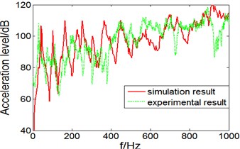
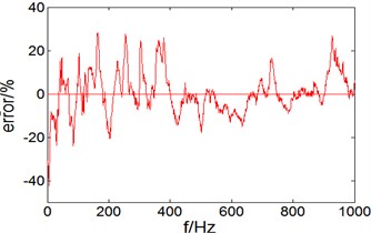
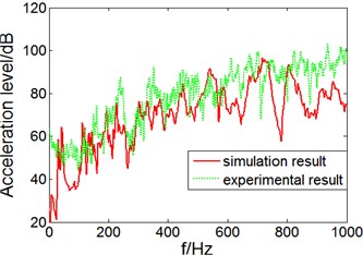
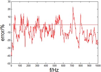
The predicted vibration acceleration level of the test points on elastic panel and inner wall of the cylindrical shell are shown in Fig. 3 and Fig. 4.
Fig. 3Vibration acceleration level and error on the elastic panel
a) Acceleration level
b) Error
Fig. 4Vibration acceleration level and error on the inner wall of cylindrical shell
a) Acceleration level
b) Error
It can be seen from Fig. 3(a) that, in the 0-1000 Hz band, vibration acceleration level prediction and experimental test result on elastic panel of a cylindrical shell are close, and spectral line at some points like 42 Hz, 104 Hz and 455 Hz can corresponds good; from Fig. 3(b), we can see in the entire frequency band 0-1000 Hz, vibration acceleration level error of prediction and experimental test result are within 20 %, especially in 400-1000 Hz band prediction error is less than 10 %, the prediction result is very close to experimental result.
In 0-1000 Hz range, calculate the total acceleration level of simulation and experiment result. The total acceleration level of simulation result is 137.8 dB, while the total acceleration level of experiment result is 135.2 dB, the error is only 2.6 dB.
It can be seen from Fig. 4(a) that, in the 0-1000 Hz band, vibration acceleration level prediction and experimental test result trends of the test points on the inner wall of cylindrical shell are basically the same, prediction in the band 0-600 Hz was very close to experimental result; from Fig. 4(b), we can see in the entire frequency band 0-1000 Hz, vibration acceleration level prediction result of the test point is smaller than experimental result, positive error is small to 10 %, negative error is as greater as 20 %, but the overall error is within 20 %. The prediction result are accurate and available.
In 0-1000 Hz range, calculate the total acceleration level of simulation and experiment result. The total acceleration level of simulation result is116.1 dB, while the total acceleration level of experiment result is 120.0 dB, the error is only 3.9 dB.
4.2. Underwater acoustic radiation prediction
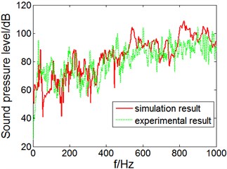
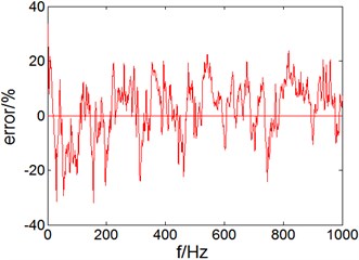
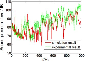
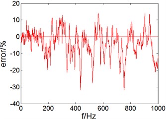
Test points collected from inner sound cavity and outer sound field of cylindrical shell, prediction and experimental result comparison of acoustic radiation is shown in Fig. 5 and Fig. 6.
Fig. 5Sound pressure level and error in inner sound cavity of cylindrical shell
a) Sound pressure level
b) Error
Fig. 6Sound pressure level and error in outer sound field of cylindrical shell
a) Sound pressure level
b) Error
It can be seen from Fig. 5(a) that, in the 0-1000 Hz frequency range, sound pressure level (SPL) prediction and experimental result trends of test points are consistent, so as resonance peak of some frequency points; from Fig. 5(b), we can see in the entire frequency band 0-1000 Hz, the SPL prediction and experimental test result error of cylindrical shell sound cavity are within 20 % and changes stably, the simulation result have high accuracy.
In 0-1000 Hz range, calculate the total sound pressure level of simulation and experiment result. The total sound pressure level of simulation result is125.6 dB, while the total sound pressure level of experiment result is 121.3 dB, the error is only 4.3 dB.
It can be seen in Fig. 6(a) that, in the 0-180 Hz band, the test point SPL of radiation outside the cylindrical shell underwater background noise described mainly, which shows that in lower frequency range radiated noise ratio is low; in 180-1000 Hz frequency, SPL prediction and experimental result trends of test points in outer sound field are consistent, but the prediction result is smaller than experimental result; from Fig. 6(b), you can see in 0-180 Hz frequency, the SPL prediction and experimental test result error of cylindrical shell in outer sound field are within 5 %, in the 180-1000 Hz band, the SPL radiation prediction error are positive error and less than 10 %, but negative error reaches 20 %. The possibly reason is background noise in outer sound field underwater is large, low signal to noise ratio result in test result is not accurate. But in general, acoustic radiation prediction of cylindrical shell underwater is of high accuracy.
In 0-1000 Hz range, calculate the total sound pressure level of simulation and experiment result. The total sound pressure level of simulation result is 119.1 dB, while the total sound pressure level of experiment result is 123.9 dB, the error is only 4.8 dB.
5. Conclusions
Establish finite element model of double cylindrical shell by software Abaqus. Based on three-dimensional sono-elasticity theory of ships, use software Thafts-acoustic to predict underwater vibration and acoustic radiation characteristics of double cylindrical shell and compared with experimental result. Results show that error of prediction result and experiment result at single frequency point is about 10 %-20 %, and error of total level of acceleration and sound pressure is less than 5 dB. Conclusions can be drawn as the following: the use of three-dimensional sono-elasticity theory of ships to predict underwater vibration and acoustic radiation characteristics of double cylindrical shell is of high accuracy, which is an effective means of underwater structure vibration and acoustic radiation prediction and can provide effective guidance for engineering applications.
References
-
Junger M. C., Feit D. Sound Structures and Their Interaction. 2nd Ed. The MIT Press, Cambridge, 1986.
-
Tang Weilin, He Bingrong Approximate analytic solution of vibration and sound radiation from stiffened finite cylindrical shells in water. Acta Acoustic, Vol. 26, Issue 1, 2001, p. 1-5, (in Chinese).
-
Caresta M., Kessissoglou N. J. Structural and acoustic responses of a fluid-loaded cylindrical hull with structural discontinuities. Applied Acoustics, Vol. 70, 2009, p. 954-963.
-
Zhou Qizheng, Wang Deshi, Gao Shengyao Research on vibration and acoustic radiation of stiffened finite cylindrical shells in water under multi-excitations. Chinese Journal of Applied Mechanics, Vol. 30, Issue 5, 2013, p. 652-657, (in Chinese).
-
Zhang Lei, Cao Yue-yun, Yang Zi-chun Structural transfer path analysis for vibration and noise of a submerged double-shell. Journal of Vibration and Shock, Vol. 31, Issue 20, 2012, p. 12-16, (in Chinese).
-
Jin Guangwen, Zhang Linke, Miao Xuhong Vibration transmissibility of a submerged cylindrical double-shell based on reconstructing velocity field. Journal of Vibration and Shock, Vol. 30, Issue 5, 2011, p. 218-221, (in Chinese).
