Abstract
The paper presents a part of ongoing research into the use of a proton exchange membrane fuel cell (PEM-FC) to power military installations and personal power supply of soldier or rescuer. Construction of this type device use elements, which generate vibration, noise and heat. Emitting these types of pollution worsens the detection of military installations as well as operator’s safety. The presented research includes the assessment of noise and vibration hazards generated by 20 Watt PEM-FC personal power supply which was created by Polish Naval Academy in consortium with Central Laboratory of Batteries and Cells in Poznan and Impact Clean Power Technology S.A. in Warsaw. Measurements of noise and vibration levels were performed in an anechoic chamber at AGH University of Science and Technology during nominal operation of the device. The vibration parameters transferred to external cover as well sound power level and the insulation effectiveness of device cover were determined.
1. Introduction
Nowadays, each of the existing or evolving military areas is dependent on electric power sources. The military requirements are very specific especially when talking about dimensions, reliability, operating conditions, power range and pollution generated into physical fields. The primary and secondary batteries would not achieve the desired value in military applications in many receivers, especially when be used as an independent power source. So, alternative power sources seem to be solution in order to comply with above requirements. Such sources can replace batteries completely or they may improve efficiency of the entire system working as hybrid electric network. The most popular portable source of electricity are low temperature polymer fuel cells, well knows as a proton exchange membrane fuel cell. PEM-FC is an electrochemical converter of energy, replacing the chemical energy into electrical energy by controlled and separated reactions, i.e. oxygen reduction reaction (ORR) and hydrogen oxidation reaction (HOR), which occurs at the cell’s cathode and anode, respectively. These types of fuel cells have gained particular popularity due to the numerous advantages over other types of fuel cells. The most important advantages include relatively low operating temperature, high energy conversion efficiency, high power density, fast start-up and environmental friendliness. Especially the advantages regarding power density and high energy conversion efficiency make this type of energy source particularly attractive for powering objects where the amount of space and mass allocated to the electric power source is strictly limited. But their construction uses elements (air or water vapor valves, air cooling fan) which generate noise and vibration, as a principle of operation requires the dissipation of heat [1].
Emitting these types of pollution into the environment worsens the detection of military installations as well as operator’s safety. This fact has become the reason for starting and conducting research on applications the PEM-FC technology to power hybrid personal power supply for military and rescue purposes [2]. The paper presents tests of noise and vibration levels emission and exposure users of hybrid power supply with a 20 Watt PEM fuel cell. Measurements were performed in an anechoic chamber at the Department of Mechanics and Vibroacoustic, AGH University of Science and Technology during nominal operation of the device.
2. PEM-FC fundamentals
The first research that brought forth the beginning of fuel cell technology dates to 1839, when William Grove presented a simple model of a cell demonstrating the basic principle of hydrogen fuel cells. In the first stage of the experiment, electrical energy was delivered to platinum electrodes immersed in the dilute acid electrolyte so that the water is disintegrated into oxygen and hydrogen. In the second part of the experiment, the current source was disconnected, and an ammeter was connected to its place, whereby an electric current was observed between the electrodes of the cell. The second part of this experiment reflects the behavior of the PEM-FC. The reactions that take place in the Grove’s cell model in the second part of his experiment are relevant for the reactions at electrodes of modern PEM hydrogen fuel cells, i.e. ORR on the cathode (1), and the HOR, that is releasing electrons from the hydrogen molecular gas, at the anode of the cell (2):
The overall reaction can be expressed as a reaction of burning hydrogen in oxygen:
However, unlike hydrogen combustion, where energy is released in the form of heat, in the fuel cells, the chemical energy is converted into electrical energy that is observable as an electrical work. Transfer of positive ions is carried out by the electrolyte, while electrons are forced to move through the external electrical circuit doing useful work [3]. The operation of PEM-FC is based on a continuous chemical reaction whose speed is determined by the current drawn from the cell. To ensure the proper functioning of the cell, it is necessary to continuously supply the cells with the reaction components to the electrodes and to remove the products from the cells. The fuel cell, when working, forces the current to flow through the circuit, which is directly related to the number of electrons released at the fuel cell anode. Consequently, the theoretical demand for fuel cell for hydrogen and oxygen is directly proportional to the current drawn from the cell. Fig. 1. shows an idea of PEM-FC work.
Since the cell stack requires cooling and air/water vapor outlet, the current demonstrator uses cooling with constant speed air fan and a water vapor valve, which are the source of vibration transmitted to the casing and further emitted to the air as an acoustic waves (noise).
3. Hybrid power supply source
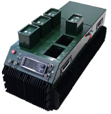
Created hybrid power supply source is a device supporting the military, rescue and evacuation actions. The solution was based on the results of research carried out as part of the research project NCBiR DOBR/0061/R/ ID2/2012/03 “Hybrid source of electrical power for devices supporting rescue and evacuation” carried out by a consortium: Polish Naval Academy (leader), Central Laboratory of Batteries and Cells in Poznan (scientific institute), Impact Clean Power Technology S.A. in Warsaw (industry). Soldiers or rescue team can work in a crisis situation without the need to supply electricity or fuel for its production. The idea of the project, especially original mechanic and electric construction of electric energy storage was born in Polish Naval Academy, Institute of Electrical Engineering and Automation. This solution consisting of a 20 Watt single power units (see Fig. 2) which can be power supply for individual man. Several units can be connected to the master system (see Fig. 3) and when can supply electric energy to field hospitals, crisis centers, lighting, communications devices, tools etc. Tests and measurement carried out in this paper were made for one unit of 20 Watt PEM-FC hybrid power supply (Fig. 2) which is in the assumption has direct contact with a human, i.e. it is mounted on a vest worn by a lifeguard or soldier.
Fig. 1Diagram of PEM-FC function [4]
![Diagram of PEM-FC function [4]](https://static-01.extrica.com/articles/20051/20051-img1.jpg)
Fig. 2View of device – 20 Watt PEM-FC hybrid power supply module
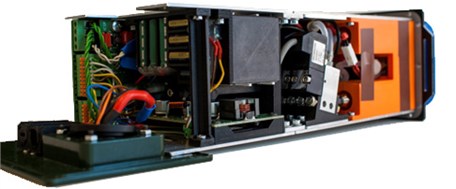
Fig. 3View of master system of 20 Watt PEM-FC hybrid power supply module
4. Guidelines on the assessment of exposure to noise and vibrations
Each member country of the European Union is obliged to implement into the internal legal system provisions of the following EU Directives: 2003/10/EC (dated 6 February 2003) [5] and 2002/44/EC (dated 25 June 2002) [6]. This regulation is on the minimum health and safety requirements regarding the exposure of workers to the risks arising from physical agents such as noise and vibration. The main requirement of these Directives is establishment of a clear and coherent prevention strategy, which would safeguard workers’ health and safety, when exposed to noise and vibration. However, the Directive does not limit the search for new methods in the transmission routes and the estimation of the impact of vibroacoustic energy on humans. In Poland research is devoted to this type problem by [7-10].
4.1. Directive 2003/10/EC guidelines
According this Directive the exposure limit values and exposure action values in respect of the daily noise exposure levels and peak sound pressure are fixed at:
a) Exposure limit values:
LEx,8h= 87 dB(A) and Ppeak= 200 Pa (140 dB (C) re. 20 μPa),
b) Upper exposure action values:
LEx,8h= 85 dB(A) and Ppeak= 140 Pa (137 dB (C) re. 20 μPa),
c) Lower exposure action values:
LEX,8h= 80 dB(A) and Ppeak= 112 Pa (135 dB (C) re. 20 μPa).
Where: Ppeak – peak sound pressure (Pa, i.e. maximum sound pressure value measure with ‘C’ frequency correction), LEX,8h – daily noise exposure level (dB(A) re. 20 μPa, i.e. is the average A – weighted noise exposure level for a nominal 8-hour working day, calculate according ISO 1999: 1990 p. 3.6 [11] and is applied to all type of noise present at work including impulsive noise.
Presented above the admissible values cannot be exceeded without taking appropriate protective for workers. According art. 6 of the directive 2003/10/EC, if the risks arising from exposure to noise cannot be prevented by other means, appropriate, properly fitting individual hearing protectors shall be made available to workers and used by them. The individual hearing protectors shall be so selected as to eliminate the risk to hearing or to reduce the risk to a minimum. On the other hand, the condition of using individual hearing protectors is difficult to meet and difficult to use in the area of military operations.
The precautionary measures set up by Directive include, in particular, designation and the occupational risk assessment made by the employer using different methods for assessing the level of exposure to noise and taking into account the circumstances of exposure. Therefore, in order to correctly assess worker exposure to noise using an objective measurement method, the Directive generally refers to ISO 1999: 1990 [11].
Important that, when applying the exposure limit values, the determination of the worker's effective exposure shall take account of the attenuation provided by the individual hearing protectors worn by the worker. The exposure action values shall not take account of the effect of any such protectors. However, in not only authors’ opinion, it would be advisable also to refer to ISO 9612: 2009 [12].
4.2. Directive 2002/44/EC guidelines
This Directive lays down minimum requirements for the protection of workers for vibration. In particular it fixes of lower values for the daily action value and the daily exposure limit value for vibrations.
For hand-arm vibration:
• The daily exposure limit value normalized to an 8-hour reference period is A(8)h= 5 m/s2,
• The daily exposure action value normalized to an 8-hour reference period is A(8)h= 2,5 m/s2.
The calculation of the daily exposure value for hand-arm vibration is based on measurement of vibration in three orthogonal axes ahwx, ahwy, ahwz defined in Chapters 4 and 5 and Annex A to standard ISO 5349-1(2001) [13]. It is expressed as the square root of the sum of the squares of the frequency-weighted acceleration values according Eq. (4):
For whole-body vibration:
• The daily exposure limit value normalized to an 8-hour reference period is A(8)w= 1,15 m/s2 or a vibration dose value (VDV) is 21 m/s1,75;
• The daily exposure action value normalized to an 8-hour reference period is 0,5 m/s2 or a vibration dose value (VDV) is 9,1 m/s1,75.
The calculation of daily exposure value for whole-body vibration for a seated or standing worker is based on measurement of vibration in three orthogonal axes with weight factors 1.4awx, 1.4awy, awz in accordance with Chapters 5, 6 and 7, Annex A and Annex B to standard ISO 2631-1(1997) [14]. It is calculated as the highest (RMS) value, or the highest vibration dose value (VDV) of the frequency-weighted accelerations according Eq. (5):
A vibration dose value (VDV) in m/s1.75 is calculate by root mean quad method using the RMS frequency weighted acceleration in m/s2 raised to 4-th power according Eq. (6):
This calculation technique ensures the vibration dose value is more sensitive to the peaks in the signal. However, in not only authors’ opinion, for whole-body vibration exposure assessments and the vibration level measurements, it should be advisable also to refer to PN-EN 14253 (2003) [15]. According to valid regulations, the correction filters used in the measurements instruments are to meet the requirements of ISO 8041 [16]. Table 1 is shown the correction filters for assessments of vibration exposure which should be used currently.
Table 1Correction filters for assessments of vibration exposure (based on ISO 8041)
Type of impact | Type of filter | Frequency range [Hz] | |
Whole-body vibration (basic filters) | |||
Direction | Vertical | Wk | 0.5-80 |
Horizontal | Wd | 0.5-80 | |
Omnidirectional (in buildings) | Wm | 1-80 | |
Whole-body vibration (extra filters) | – | – | |
Direction | Horizontal (on a seat back rest) | Wc | 0.5-80 |
Vertical recumbent (for head) | Wj | 0.5-80 | |
Hand-arm vibration | Wh | 8-1000 | |
5. Vibroacoustic tests of device
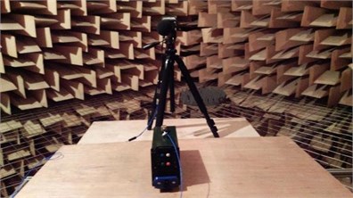
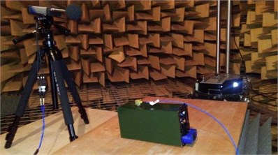
Measurements of noise and vibration levels of 20 Watt PEM-FC personal power supply were performed in an anechoic chamber at AGH University of Science and Technology, Department of Mechanics and Vibroacoustic during nominal operation of the device (see Fig. 4(a) and Fig. 4(b)). The measurement condition met the requirements described in ISO 3745:2012 [17]. For sound and vibration measurements, the SVAN 958 level meter was used, equipped with the free field microphone (40AZ G.R.A.S) and 3-Axis vibration sensor (356B18 PCB Piezotronics). This level meter allows perform in 1 class sound pressure level measurements – i.e. Lmax, Lmin, Leq, SEL, Lpeak with A, C, Z correction filter and FAST time constant in parallel and multispectrum in 1/3 octave bands, as well as allows measure the vibration acceleration parameters - RMS, PP, Peak, Max, VDV with HP, Wk, Wd, Wm, Wh correction filter independently in three axes (ax, ay, az). The measurement coherence ensured the acoustic calibration by SV30A SVANTEK with SPL level 113.9 dB and vibration calibration by 4294 Bruel & Kjaer source with an acceleration level of 10 m/s2.
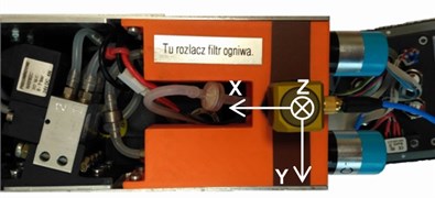
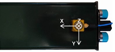
Vibration acceleration measurements were performed in two variants: without and with external cover, in 3 different places simultaneously in three directions: x, y, z (see Fig. 5(a) and Fig. 5(b)). Measurement for the same working conditions with and without the cover allowed the basic assessment of the effectiveness of protection against vibrations emitted by the PEM-FC.
Fig. 4Device during vibroacoustic test in anechoic chamber: a) rear view of the device, b) side view of the device
a)
b)
Fig. 5View of two variant mounting the accelerometer: a) without external cover, b) with external cover
a)
b)
5.1. Noise test
As a result of the acoustic study of device, according procedures describe in [17] it was measure and calculate that acoustic power of dives with cover is equal LWA= 45 dB (A). Because in the operating conditions the source is mounted on users’ vest, it should be treated that we are dealing with vibroacoustic phenomena in the near field. Therefore, it should be assumed that the level of acoustic pressure A at head height should not exceed LAeq= 45 dB (A). During tests, maximum peak level was LCpeak= 87.1 dB (C) and maximum sound pressure level was LAmax= 62.2 dB (A). This is due to the operation of a water vapor release valve (see periodic peaks on Leq/LAeq curve at Fig. 7). The noise level (LAeq) of the cooling fan of the cell assembly is 43 dB (A). The average (5 minutes of work) spectrum of sound power level is presented at Fig. 6. Sound pressure level (Leq) and A-weighted sound pressure level (LAeq) courses for half minute of work are shown at Fig. 7.
5.2. Vibration test
Acceleration parameters for had-arm and whole-body vibration assessment perform with HP filter in frequency band 0.5-3000 Hz are shown in Table 2.
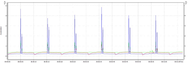
The above results indicate that used cover dampens a vibration by half. Exemplary RMS acceleration courses (ax, ay, az) generated by device with and without cover are presented at Fig. 8 and Fig 9. Made measurements and calculations indicate that, the exposure level and vibration dose are not exceeded with reference to directive 2002/44/EC for the evaluation in whole-body and hand-arm vibration.
Fig. 6Unweighted average (5 minutes of work) spectrum of the sound power level LW, total A-weighted sound power level LWA, total C-weighted sound power level LWC, total unweighted sound power level LWC generated by 20W PEM hybrid power supply module
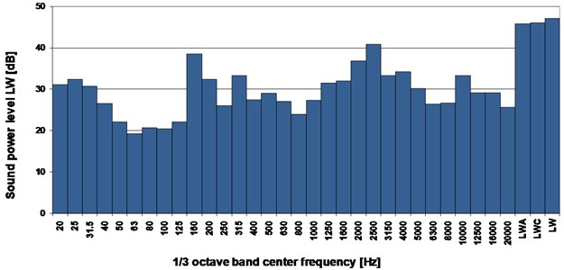
Fig. 7Sound pressure level – Leq(red line), A-weighted sound pressure level – LAeq (black line) time courses during device nominal work (example 30 second of work)
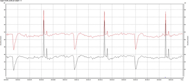
Fig. 8RMS acceleration courses ax (red line), ay (green line), az (blue line) generated by device. Measurement in accelerometer position I without cover
6. Noise and vibration control
The mechanical design of the 20 Watt PEM-FC personal power supply cover was made with the assumption of striving for a lightweight and compact construction. The distribution of elements ensures good mechanical strength obtained, among others, thanks to the use of three frames sealing all housing covers. An important design assumption was to ensure an adequate air flow through the electronic modules, so that they were sufficiently cooled. On the other hand, it is necessary to provide the hydrogen cell with warm air at its inlet. It was decided to use the flow generated by the cell fan to cool the electronics, while using the heat generated by it to preheat the air used by the stack (see Fig. 10). The fuel cell stack is designed to operate at 65 °C. At this operating temperature, the air exhaust stream temperature can reach 55 °C and the cooling air stream can reach 17 °C above ambient conditions. These temperatures are sufficient to cause burns or severe discomfort. Accordingly, avoid contact with the fuel cell stack, or components that convey process or cooling air. The designed cover design assures this requirement.
Fig. 9RMS acceleration ax (red line), ay (green line), az (blue line) generated by device. Measurement in accelerometer position 1 with cover
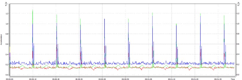
Table 2Average results of acceleration parameters for 5 minute of device work
Accel. position | Cover | ahv [m/s2] | awv [m/s2] | VDV [m/s1.75] | RMS [m/s2] | PEAK [m/s2] | ||||
ax | ay | az | ax | ay | az | |||||
1 | With | 0.34 | 0.41 | 1.93 | 0.15 | 0.19 | 0.25 | 8.3 | 20.6 | 23.1 |
Without | 0.74 | 0.91 | 3.84 | 0.35 | 0.41 | 0.52 | 13.3 | 13.5 | 63.9 | |
2 | With | 0.46 | 0.59 | 2.38 | 0.27 | 0.22 | 0.28 | 18.1 | 22.9 | 20.2 |
Without | 0.8 | 1.04 | 4.06 | 0.31 | 0.56 | 0.41 | 14.6 | 14.6 | 16.4 | |
3 | With | 0.31 | 0.37 | 1.57 | 0.14 | 0.17 | 0.25 | 11.6 | 13.1 | 21.8 |
Without | 0.79 | 1.07 | 3.96 | 0.31 | 0.69 | 0.26 | 13.1 | 18.1 | 20.2 | |
Single fuel cell stack (Fig. 11) includes a plurality of plate-like fuel cells arranged along an axis generally parallel to cell thickness with electrically conductive separator plates between each pair of cells and it is integrated with cooling fan. The sources of noise in the used fan are air flowing through the fan blade system (aerodynamic noise) and mechanical vibrations caused by the operation of the bearings and appearing an unbalance of the rotor due to the dusting of its blades (mechanical noise). In general, in fans with a lower peripheral speed of the blades and a lower flow velocity in the main duct (on the order of 8 m/s), the noise of aerodynamic origin is less than mechanical noise. At higher velocities, the decisive role is played by the noise of aerodynamic origin, which is caused by changes in the pressure distribution on the surface of the blades caused by periodic cutting of the air stream by the blades (noise due to the inhomogeneity of the air stream). In this type of fans (axial), this noise occurs when the blades of the steering wheel and the rotor pass, and it depends on the value of the number of blades selection, the distance between the shoulder crowns and the distance of the rim from its structural elements.
The device used a fan with 7 blades, nominal speed of the rotor is 1400 rpm and it has rolling bearing. As measured, the noise level (LAeq) of the cooling fan nominal work is 43 dB (A). It is possible by using a hydrodynamic slide bearing instead of a rolling bearing to reduce the noise level by 15/25 dB (A), and additionally by using a larger number of blades (e.g. 11 blades) it is possible to reduce the rotor speed to about 900 rpm while maintaining a similar air exchange.
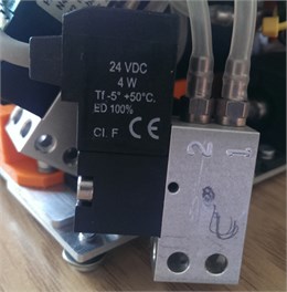
Purge valve (see Fig. 12) controls the purging time for purging water and redundant hydrogen from the fuel cells. The valve is electrically controlled by an actuator opening or closing the valve. The operation of the solenoid valve actuator itself is not loud, however, under the load of water vapor pressure, it causes a pulsed acoustic phenomenon (LAmax= 62.2 dB (A) and LCpeak= 87.1 dB (C). One of the possible ways to reduce the negative vibroacoustic operation of the valve is to use a compression damper, which effectiveness can reach up to 30 dB (A).
All construction details of the final version of 20 Watt PEM-FC hybrid power supply module were not included due to the purpose of the system to support the activities of state units in crisis situations.
Fig. 10Air flow in cover
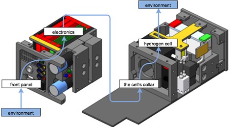
Fig. 11Fuel cell stack with integrated cooling fan
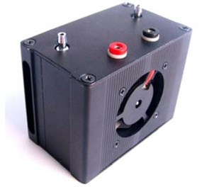
Fig. 12Fuel cell stack valve
7. Conclusions
The permissible levels of noise and vibration exposure are not exceeded by 20 Watt hybrid PEM-FC personal power supply module with reference to directive 2003/10/EC and 2002/44/EC. Thus, the device is safe for the users to be at risk of noise and vibration hazard. In addition, research has found that the device is not so quiet that it could guarantee full freedom in military operations. Further research and design work will be carried out by the authors to minimize the emission of vibroacoustic energy to the environment, for 20 Watt hybrid PEM-FC personal power supply module to become a device with even less noise and vibration levels. Because the innovative power module structure was adopted, based on intelligent, hybrid combination of various energy storage and processing technologies, typical methods of design optimization do not allow achieving the goal. For example, the multifunctionality of a fan that ensures the optimal flow of oxygen as a reagent, maintaining the right temperature of the stack as well as the cooling of electronic modules, required experimental methods to optimize the adopted solutions.
References
-
Grzegorz G., Listewnik K., Klaczynski M., Cioch W. Examination of the vibroacoustic characteristics of 6 kW proton exchange membrane fuel cell. Journal of Vibroengineering, Vol. 17, Issue 7, 2015, p. 4025-4034.
-
Kłaczyński M., Grzeczka G. Noise and vibration exposure of hybrid PEM power supply users during its operation. Vibroengineering Procedia, Vol. 13, 2017, p. 233-238.
-
Polak A., Grzeczka G., Piłat T. Influence of cathode stoichiometry on operation of PEM fuel cells’ stack supplied with pure oxygen. Journal of Marine Engineering and Technology, Vol. 16, Issue 4, 2017, p. 283-290.
-
Pem Fuel Cell Schematic, https://pl.pinterest.com/pin/480337116478162386.
-
DIRECTIVE 2003/10/EC of The European Parliament and of the Council of 6 February 2003 on the Minimum Health and Safety Requirements Regarding the Exposure of Workers to the Risks Arising from Physical Agents (Noise) (Seventeenth Individual Directive Within the Meaning of Article 16(1) of Directive 89/391/EEC). Official Journal of the European Union, L 42/38, 2003.
-
DIRECTIVE 2002/44/EC of the European Parliament and of the Council of 25 June 2002 on the Minimum Health and Safety Requirements Regarding the Exposure of Workers to the Risks Arising from Physical Agents (Vibration) (Sixteenth Individual Directive Within the Meaning of Article 16(1) of Directive 89/391/EEC). Official Journal of the European Communities, L 177/13, 2002.
-
Baranski R. Searching for new measurement solutions in the area of estimating danger of local vibrations at workplace. Acta Physica Polonica A, Vol. 118, Issue 1, 2010, p. 3-6.
-
Baranski R., Kozupa A. Hand grip-EMG muscle response. Acta Physica Polonica A, Vol. 125, Issue 4A, 2014, p. 7-10.
-
Burdzik R. Identification of structure and directional distribution of vibration transferred to car-body from road roughness. Journal of Vibroengineering, Vol. 16, Issue 1, 2014, p. 324-333.
-
Burdzik R., Konieczny L. Application of vibroacoustic methods for monitoring and control of comfort and safety of passenger cars. Solid State Phenomena, Vol. 210, 2014, p. 20-25.
-
ISO 1999:1990 Acoustics – Determination of Occupational Noise Exposure and Estimation of Noise-Induced Hearing Impairment (updated ISO 1999:2013).
-
ISO 9612:2009 Acoustics – Determination of Occupational Noise Exposure – Engineering Method.
-
ISO 5349-1:2001 Mechanical Vibration – Measurement and Evaluation of Human Exposure to Hand-Transmitted Vibration – Part 1: General Requirements.
-
ISO 2631-1:1997 Mechanical Vibration and Shock – Evaluation of Human Exposure to Whole-Body Vibration - Part 1: General Requirements.
-
PN-EN 14253:2003 Mechanical Vibration. Measurement and Calculation of Occupational Exposure to Whole-Body Vibration with Reference to Health. Practical Guidance.
-
ISO 8041-1:2017 Human Response to Vibration – Measuring Instrumentation – Part 1: General Purpose Vibration Meters.
-
ISO 3745:2012 Acoustics – Determination of Sound Power Levels and Sound Energy Levels of Noise Sources Using Sound Pressure – Precision Methods for Anechoic Rooms and Hemi-Anechoic Rooms.

